EP0336025A1 - Measurement method and apparatus using time domain reflectrometry - Google Patents
Measurement method and apparatus using time domain reflectrometry Download PDFInfo
- Publication number
- EP0336025A1 EP0336025A1 EP88302996A EP88302996A EP0336025A1 EP 0336025 A1 EP0336025 A1 EP 0336025A1 EP 88302996 A EP88302996 A EP 88302996A EP 88302996 A EP88302996 A EP 88302996A EP 0336025 A1 EP0336025 A1 EP 0336025A1
- Authority
- EP
- European Patent Office
- Prior art keywords
- target
- transmission line
- signal
- measurement
- line
- Prior art date
- Legal status (The legal status is an assumption and is not a legal conclusion. Google has not performed a legal analysis and makes no representation as to the accuracy of the status listed.)
- Granted
Links
Images


Classifications
-
- G—PHYSICS
- G01—MEASURING; TESTING
- G01B—MEASURING LENGTH, THICKNESS OR SIMILAR LINEAR DIMENSIONS; MEASURING ANGLES; MEASURING AREAS; MEASURING IRREGULARITIES OF SURFACES OR CONTOURS
- G01B7/00—Measuring arrangements characterised by the use of electric or magnetic techniques
- G01B7/02—Measuring arrangements characterised by the use of electric or magnetic techniques for measuring length, width or thickness
Definitions
- This invention relates to a measurement method and to measurement apparatus using time domain reflectometry (TDR).
- TDR time domain reflectometry
- time domain reflectometry is widely established as a means of identifying the presence of faults within electromagnetic cables and transmission lines, and of locating their position. Any fault will modify the characteristic impedance of the transmission line to incident electromagnetic waves which will hence be partially reflected. The reflected wave can be detected at the input end of the cable and the location of the fault determined from the time at which the reflection arrives.
- a method of precision length or position measurement which comprises:- a) extending a transmission line in a predetermined spatial orientation with respect to an object on which a length or position measurement is required; b) moving along the transmission line a target adapted by its proximity to the line to alter the impedance of the line at the position along the line at which the target is located; c) directing an electromagnetic signal into an input end of the line and measuring the time at which an electromagnetic signal is returned to the input end due to partial reflection of the input signal at the location of the target; and d) processing the returned signal to evaluate the position of the target along the line, thereby precisely to determine a length or position measurement on the object.
- the transmission line may extend parallel with the object (for precision length measurement), or the transmission line could adopt any other predetermined shape, such as an arc of a circle, in which case the predetermined shape and the position of the target will enable an accurate position measurement (such as an angular measurement) to be obtained.
- the method in accordance with the invention may be a method employed simply for precision length determination, the result being displayed, or the method may be extended, by feeding the output of the processing means to a suitable controller, to include the step of carrying out a manufacturing step, e.g. cutting, on the object, at a position thereon determined by the precision length measurement.
- a manufacturing step e.g. cutting
- movement of the target along the transmission line is arranged to be representative of the movement of the processing tool relative to the work piece.
- this may be effected with the target stationary at a position to which it has been moved, whilst in the case of a manufacturing method, one or more processing means may operate at a selected measured position or successive measured positions along the object, as the target is moved along the transmission line.
- a fast acting processing means is necessary substantially instantaneously to give a length determination corresponding to the instantaneous position of the target, and further features of the present invention, detailed hereinafter, make this possible.
- measurement apparatus comprising: - a transmission line adapted to propagate electromagnetic energy whose characteristic impedance is altered by the proximity of a target which is movable along the transmission line; - a signal source which generates a fast-rising, short pulse which is directed into an input end of the transmission line and is partially reflected at the target; and - means for processing the reflected signal to evaluate the position of the target.
- an open electromagnetic transmission line can be designed so that the presence of objects in its vicinity will similarly modify the characteristic impedance and thus cause a detectable reflection.
- This property has then been utilised by designing a target which can move along the transmission line.
- the transmission line is itself of such a characteristic impedance that there is preferably a reflection at the input of the transmission line and a reflection from the movable target, and the time difference between these two events is the basis of the precision length measurement.
- Traditional laboratory time domain reflectometers utilise a fast-rising step input signal with a rise time of less than around 100 ps and sample the reflected waveform at a sequence of delays, thus requiring many pulses to derive one measurement.
- a different method of processing the reflected waveform is utilised, which does not use a sampler, but extracts a time delay measurement by integration during the period of one or a series of pulses.
- the processing means comprises a flip-flop circuit such as a GaAs high speed flip-flop, which is triggered on and off by respective reflected pulses and causes a precision current source to be turned on and off.
- the instant length measurement is then indicated by the charge delivered by the current source to an integration circuit following one or multiple signal pulses.
- This preferred apparatus can provide substantially instantaneous measurement corresponding to the instantaneous position of the target.
- the preferred means for processing the TDR output can be designed with the advantage of producing a length measurement from a single pulse. This means that precision length measurement of a relatively fast moving target is available in a fraction of a millisecond.
- the position of a target 28 along a transmission line 24 is measured by using the reflection from the input end of the transmission line to flip a GaAs flip-flop 10.
- the reflection from the target 28 then switches the GaAs flip-flop 10 back to its original level.
- the output from the flip-flop is used to switch a stable current source 12 into an integrator 14 which measures the duty cycle of the current which is proportional to the length of the 'ON' pulse and therefore to the position of the target.
- the voltage output of the integrator proportional to the time delay is fed to an A/D converter 16.
- the output from the analogue-to-digital converter 16 may either be passed to a display in a measurement application or to a controller in a manufacturing process.
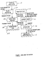
- Figure 1 also shows a signal generator, which comprises a crystal oscillator 18 and a pulse geneerator 20, together with a directional coupler 22 through which the pulse input is fed into the input end of the transmission line 24.
- a signal generator which comprises a crystal oscillator 18 and a pulse geneerator 20, together with a directional coupler 22 through which the pulse input is fed into the input end of the transmission line 24.
- a waveform in the form of a short voltage pulse ( Figure 3) is applied to the input end of the transmission line 24 via the directional coupling network 22.
- the transmission line is of a different impedance to the coupler output and there is thus a reflection due to this impedance discontinuity.
- the transmission line is then uniform except at the point where the target is located. There is then a reflection at the target, resulting in a complete reflected waveform of the form shown in Figure 4A.
- the reflected waveform ( Figure 4A) is used to switch the GaAs flip-flop 10 between its two states and gives rise to the output rectangular wave ( Figure 4B). This waveform is then used to switch a stable current from source 12 into the integration circuit 14, which measures the duty cycle of the flip-flop output.
- the time constant of the integration circuit is chosen according to the measurement accuracy required. For instance, if the reflected waveform has root mean square jitter of 10 picoseconds and a timing accuracy of 1 picosecond is required, then the integration circuit must integrate over 100 pulses.
- the output voltage (see Figure 5) from the integration circuit 14 is passed to the analogue-to-digital converter 16 whose reference is derived from the stable current source 12.
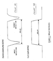
- FIG. 2A Two embodiments of the transmission line are shown in Figure 2.
- a metal or dielectric cursor 30 is suspended between an air spaced parallel plate transmission line 32.
- a metal or dielectric cursor 34 rides as a saddle along a transmission line 36 which comprises 2 parallel metal plates separated by an insulating layer of dielectric material.
Abstract
Description
- This invention relates to a measurement method and to measurement apparatus using time domain reflectometry (TDR).
- The technique of time domain reflectometry is widely established as a means of identifying the presence of faults within electromagnetic cables and transmission lines, and of locating their position. Any fault will modify the characteristic impedance of the transmission line to incident electromagnetic waves which will hence be partially reflected. The reflected wave can be detected at the input end of the cable and the location of the fault determined from the time at which the reflection arrives.
- According to one aspect of the present invention, there is provided a method of precision length or position measurement which comprises:- a) extending a transmission line in a predetermined spatial orientation with respect to an object on which a length or position measurement is required; b) moving along the transmission line a target adapted by its proximity to the line to alter the impedance of the line at the position along the line at which the target is located; c) directing an electromagnetic signal into an input end of the line and measuring the time at which an electromagnetic signal is returned to the input end due to partial reflection of the input signal at the location of the target; and d) processing the returned signal to evaluate the position of the target along the line, thereby precisely to determine a length or position measurement on the object.
- The transmission line may extend parallel with the object (for precision length measurement), or the transmission line could adopt any other predetermined shape, such as an arc of a circle, in which case the predetermined shape and the position of the target will enable an accurate position measurement (such as an angular measurement) to be obtained.
- The method in accordance with the invention may be a method employed simply for precision length determination, the result being displayed, or the method may be extended, by feeding the output of the processing means to a suitable controller, to include the step of carrying out a manufacturing step, e.g. cutting, on the object, at a position thereon determined by the precision length measurement. Thus, in a manufacturing operation, movement of the target along the transmission line is arranged to be representative of the movement of the processing tool relative to the work piece.
- Moreover, in the case of simple measurement, this may be effected with the target stationary at a position to which it has been moved, whilst in the case of a manufacturing method, one or more processing means may operate at a selected measured position or successive measured positions along the object, as the target is moved along the transmission line. In the latter case, a fast acting processing means is necessary substantially instantaneously to give a length determination corresponding to the instantaneous position of the target, and further features of the present invention, detailed hereinafter, make this possible.
- According to another aspect of the invention, there is provided measurement apparatus comprising:
- a transmission line adapted to propagate electromagnetic energy whose characteristic impedance is altered by the proximity of a target which is movable along the transmission line;
- a signal source which generates a fast-rising, short pulse which is directed into an input end of the transmission line and is partially reflected at the target; and
- means for processing the reflected signal to evaluate the position of the target. - Thus, in developing the present invention, the Applicants have shown by experimentation that an open electromagnetic transmission line can be designed so that the presence of objects in its vicinity will similarly modify the characteristic impedance and thus cause a detectable reflection. This property has then been utilised by designing a target which can move along the transmission line. The transmission line is itself of such a characteristic impedance that there is preferably a reflection at the input of the transmission line and a reflection from the movable target, and the time difference between these two events is the basis of the precision length measurement.
- Traditional laboratory time domain reflectometers utilise a fast-rising step input signal with a rise time of less than around 100 ps and sample the reflected waveform at a sequence of delays, thus requiring many pulses to derive one measurement. In the present invention a different method of processing the reflected waveform is utilised, which does not use a sampler, but extracts a time delay measurement by integration during the period of one or a series of pulses.
- In a preferred apparatus, the processing means comprises a flip-flop circuit such as a GaAs high speed flip-flop, which is triggered on and off by respective reflected pulses and causes a precision current source to be turned on and off. The instant length measurement is then indicated by the charge delivered by the current source to an integration circuit following one or multiple signal pulses. This preferred apparatus can provide substantially instantaneous measurement corresponding to the instantaneous position of the target. Thus, the preferred means for processing the TDR output can be designed with the advantage of producing a length measurement from a single pulse. This means that precision length measurement of a relatively fast moving target is available in a fraction of a millisecond.
- The method and apparatus in accordance with the invention is exemplified in the following description, making reference to the accompanying drawings, in which:-
- Figure 1 is a block diagram of a practical arrangement, indicating the components used in one particular embodiment of the sensor system;
- Figure 2 is a diagram of alternative designs of the transmission line and target suitable for precision length measurement;
- Figure 3 shows an incident pulse appropriate for precision length measurement. The amplitude, rise time and fall time of the pulse may be varied according to the measurement precision required;
- Figure 4 shows the reflected wave coupled into the flip-flop and the associated output from the flip-flop; and
- Figure 5 shows the associated current in an integration circuit whose output is passed to an analogue-to-digital converter whose reference is derived from a stable current source.
- In the preferred apparatus shown in Figure 1, the position of a
target 28 along atransmission line 24 is measured by using the reflection from the input end of the transmission line to flip a GaAs flip-flop 10. The reflection from thetarget 28 then switches the GaAs flip-flop 10 back to its original level. The output from the flip-flop is used to switch a stablecurrent source 12 into anintegrator 14 which measures the duty cycle of the current which is proportional to the length of the 'ON' pulse and therefore to the position of the target. The voltage output of the integrator proportional to the time delay is fed to an A/D converter 16. The output from the analogue-to-digital converter 16 may either be passed to a display in a measurement application or to a controller in a manufacturing process. - Figure 1 also shows a signal generator, which comprises a
crystal oscillator 18 and apulse geneerator 20, together with adirectional coupler 22 through which the pulse input is fed into the input end of thetransmission line 24. - A waveform in the form of a short voltage pulse (Figure 3) is applied to the input end of the
transmission line 24 via thedirectional coupling network 22. The transmission line is of a different impedance to the coupler output and there is thus a reflection due to this impedance discontinuity. The transmission line is then uniform except at the point where the target is located. There is then a reflection at the target, resulting in a complete reflected waveform of the form shown in Figure 4A. - The reflected waveform (Figure 4A) is used to switch the GaAs flip-
flop 10 between its two states and gives rise to the output rectangular wave (Figure 4B). This waveform is then used to switch a stable current fromsource 12 into theintegration circuit 14, which measures the duty cycle of the flip-flop output. The time constant of the integration circuit is chosen according to the measurement accuracy required. For instance, if the reflected waveform has root mean square jitter of 10 picoseconds and a timing accuracy of 1 picosecond is required, then the integration circuit must integrate over 100 pulses. - The output voltage (see Figure 5) from the
integration circuit 14 is passed to the analogue-to-digital converter 16 whose reference is derived from the stablecurrent source 12. The output from the analogue-to-digital converter 16 is proportional to the time delay (t) of the cursor, which can be converted to a length through the relationship x = ct/2, where (c) is the velocity of propagation of electromagnetic waves down the transmission line. This length can either be displayed or used to position a cutter or other processing tool acting on an object or article disposed parallel to the transmission line. - Two embodiments of the transmission line are shown in Figure 2. In Figure 2A, a metal or
dielectric cursor 30 is suspended between an air spaced parallelplate transmission line 32. In Figure 2B, a metal or dielectric cursor 34 rides as a saddle along atransmission line 36 which comprises 2 parallel metal plates separated by an insulating layer of dielectric material. - Various modifications of the afore-described and illustrated method and apparatus are possible within the scope of the invention hereinbefore defined.
Claims (10)
- a transmission line adapted to propagate electromagnetic energy whose characteristic impedance is altered by the proximity of a target which is movable along the transmission line;
- a signal source which generates a fast-rising, short pulse which is directed into an input end of the transmission line and is partially reflected at the target; and
- means for processing the reflected signal to evaluate the position of the target.
Priority Applications (4)
| Application Number | Priority Date | Filing Date | Title |
|---|---|---|---|
| ES198888302996T ES2035916T3 (en) | 1988-04-05 | 1988-04-05 | METHOD AND MEASURING DEVICE USING TEMPERAL DOMAIN REFLECTOMETRY. |
| DE8888302996T DE3876420T2 (en) | 1988-04-05 | 1988-04-05 | TIME AREA REFLECTOMETRY MEASUREMENT METHOD AND ARRANGEMENT FOR ITS PERFORMANCE. |
| EP88302996A EP0336025B1 (en) | 1988-04-05 | 1988-04-05 | Measurement method and apparatus using time domain reflectrometry |
| AT88302996T ATE83067T1 (en) | 1988-04-05 | 1988-04-05 | TIME DOMAIN REFLECTOMETRIC MEASUREMENT METHOD AND ARRANGEMENTS FOR PERFORMING THEREOF. |
Applications Claiming Priority (1)
| Application Number | Priority Date | Filing Date | Title |
|---|---|---|---|
| EP88302996A EP0336025B1 (en) | 1988-04-05 | 1988-04-05 | Measurement method and apparatus using time domain reflectrometry |
Publications (2)
| Publication Number | Publication Date |
|---|---|
| EP0336025A1 true EP0336025A1 (en) | 1989-10-11 |
| EP0336025B1 EP0336025B1 (en) | 1992-12-02 |
Family
ID=8200016
Family Applications (1)
| Application Number | Title | Priority Date | Filing Date |
|---|---|---|---|
| EP88302996A Expired EP0336025B1 (en) | 1988-04-05 | 1988-04-05 | Measurement method and apparatus using time domain reflectrometry |
Country Status (4)
| Country | Link |
|---|---|
| EP (1) | EP0336025B1 (en) |
| AT (1) | ATE83067T1 (en) |
| DE (1) | DE3876420T2 (en) |
| ES (1) | ES2035916T3 (en) |
Cited By (6)
| Publication number | Priority date | Publication date | Assignee | Title |
|---|---|---|---|---|
| US5734346A (en) * | 1992-05-23 | 1998-03-31 | Cambridge Consultants Limited | Method of an apparatus for detecting the displacement of a target |
| EP0851215A1 (en) * | 1996-12-26 | 1998-07-01 | Nikon Corporation | Angle detection apparatus |
| EP1595157A1 (en) * | 2003-02-20 | 2005-11-16 | Raytheon Company | Method and system for electrical length matching |
| GB2435358A (en) * | 2006-02-15 | 2007-08-22 | Schlumberger Holdings | Determining a well depth by measuring a length of an electrical cable |
| AT508294B1 (en) * | 2009-06-08 | 2012-04-15 | Advanced Drilling Solutions Gmbh | DEVICE FOR DETECTING THE LENGTH OF A DRILLING BRACKET |
| DE112007003213B4 (en) * | 2007-07-23 | 2018-02-15 | TRUMPF Hüttinger GmbH + Co. KG | Method for determining the wave transit time between at least one inverter in a plasma power supply device and a load and plasma power supply device connected thereto |
Citations (3)
| Publication number | Priority date | Publication date | Assignee | Title |
|---|---|---|---|---|
| US3898555A (en) * | 1973-12-19 | 1975-08-05 | Tempo Instr Inc | Linear distance measuring device using a moveable magnet interacting with a sonic waveguide |
| US4135397A (en) * | 1977-06-03 | 1979-01-23 | Krake Guss L | Level measuring system |
| EP0229505A1 (en) * | 1985-12-16 | 1987-07-22 | Fujitsu Limited | A method of measuring a cable delay time |
-
1988
- 1988-04-05 ES ES198888302996T patent/ES2035916T3/en not_active Expired - Lifetime
- 1988-04-05 AT AT88302996T patent/ATE83067T1/en not_active IP Right Cessation
- 1988-04-05 DE DE8888302996T patent/DE3876420T2/en not_active Expired - Fee Related
- 1988-04-05 EP EP88302996A patent/EP0336025B1/en not_active Expired
Patent Citations (3)
| Publication number | Priority date | Publication date | Assignee | Title |
|---|---|---|---|---|
| US3898555A (en) * | 1973-12-19 | 1975-08-05 | Tempo Instr Inc | Linear distance measuring device using a moveable magnet interacting with a sonic waveguide |
| US4135397A (en) * | 1977-06-03 | 1979-01-23 | Krake Guss L | Level measuring system |
| EP0229505A1 (en) * | 1985-12-16 | 1987-07-22 | Fujitsu Limited | A method of measuring a cable delay time |
Non-Patent Citations (1)
| Title |
|---|
| WIRELESS WORLD, vol. 89, no. 1571, August 1983, page 39, Olchester, GB; A. SUTER: "Direct reading cable reflectometer" * |
Cited By (9)
| Publication number | Priority date | Publication date | Assignee | Title |
|---|---|---|---|---|
| US5734346A (en) * | 1992-05-23 | 1998-03-31 | Cambridge Consultants Limited | Method of an apparatus for detecting the displacement of a target |
| EP0851215A1 (en) * | 1996-12-26 | 1998-07-01 | Nikon Corporation | Angle detection apparatus |
| EP1595157A1 (en) * | 2003-02-20 | 2005-11-16 | Raytheon Company | Method and system for electrical length matching |
| CN100442075C (en) * | 2003-02-20 | 2008-12-10 | 雷西昂公司 | Method and system for electrical length matching |
| GB2435358A (en) * | 2006-02-15 | 2007-08-22 | Schlumberger Holdings | Determining a well depth by measuring a length of an electrical cable |
| GB2435358B (en) * | 2006-02-15 | 2009-02-18 | Schlumberger Holdings | Well depth measurement |
| US8269647B2 (en) | 2006-02-15 | 2012-09-18 | Schlumberger Technology Corporation | Well depth measurement using time domain reflectometry |
| DE112007003213B4 (en) * | 2007-07-23 | 2018-02-15 | TRUMPF Hüttinger GmbH + Co. KG | Method for determining the wave transit time between at least one inverter in a plasma power supply device and a load and plasma power supply device connected thereto |
| AT508294B1 (en) * | 2009-06-08 | 2012-04-15 | Advanced Drilling Solutions Gmbh | DEVICE FOR DETECTING THE LENGTH OF A DRILLING BRACKET |
Also Published As
| Publication number | Publication date |
|---|---|
| EP0336025B1 (en) | 1992-12-02 |
| ES2035916T3 (en) | 1993-05-01 |
| DE3876420T2 (en) | 1993-04-08 |
| ATE83067T1 (en) | 1992-12-15 |
| DE3876420D1 (en) | 1993-01-14 |
Similar Documents
| Publication | Publication Date | Title |
|---|---|---|
| US6801157B2 (en) | Guided wave radar level transmitter | |
| US3995212A (en) | Apparatus and method for sensing a liquid with a single wire transmission line | |
| US7823446B2 (en) | Pulsed radar level gauging with relative phase detection | |
| GB2283632A (en) | Device for testing an electrical line | |
| CN101334308A (en) | Artificial circuit for checking flow gauge | |
| EP0182834A1 (en) | Optoelectric distance measuring apparatus with a time discriminator for the accurate detection of the electric pulse sequence | |
| EP0336025A1 (en) | Measurement method and apparatus using time domain reflectrometry | |
| US20190195674A1 (en) | Precision adc sampling clock for high accuracy wireless guided wave radar | |
| JPS5737257A (en) | Bonding inspection apparatus | |
| JPS57136107A (en) | Ultrasonic thickness measuring method and apparatus | |
| US2862200A (en) | Measuring apparatus | |
| GB2055269A (en) | Checking the location of moving parts in a machine | |
| US4196406A (en) | Ultrasonic control device | |
| JP3198904B2 (en) | Conductor length measuring device and level measuring device | |
| CN106405569A (en) | Laser distance measurement method based on mode-locked pulse sequence, and system thereof | |
| JPS639182B2 (en) | ||
| RU2150747C1 (en) | Device for counting separate pieces that move over conveyor | |
| EP0018079A1 (en) | Digital type ultrasonic holographic apparatus | |
| EP0324855A1 (en) | Method and apparatus for ultrasonic flaw detection | |
| KR100542866B1 (en) | Time Domain Reflectometer utilizing a low frequency clock generator and a low speed ADC | |
| SU864191A1 (en) | Device for indicating time delay of switching elements | |
| US4775244A (en) | Method and apparatus for measurement of pulse width of very short pulses | |
| Ross | Early developments and motivations for time-domain analysis and application | |
| Opalska et al. | A pulser with inverted microstrip line for time-domain reflectometry | |
| SU845004A2 (en) | Converter of light intensity distribution into electric signal sequence |
Legal Events
| Date | Code | Title | Description |
|---|---|---|---|
| PUAI | Public reference made under article 153(3) epc to a published international application that has entered the european phase |
Free format text: ORIGINAL CODE: 0009012 |
|
| AK | Designated contracting states |
Kind code of ref document: A1 Designated state(s): AT CH DE ES FR GB IT LI NL SE |
|
| 17P | Request for examination filed |
Effective date: 19891107 |
|
| RAP3 | Party data changed (applicant data changed or rights of an application transferred) |
Owner name: DR. JOHANNES HEIDENHAIN GMBH |
|
| 17Q | First examination report despatched |
Effective date: 19910614 |
|
| ITF | It: translation for a ep patent filed |
Owner name: DE DOMINICIS & MAYER S. |
|
| GRAA | (expected) grant |
Free format text: ORIGINAL CODE: 0009210 |
|
| AK | Designated contracting states |
Kind code of ref document: B1 Designated state(s): AT CH DE ES FR GB IT LI NL SE |
|
| REF | Corresponds to: |
Ref document number: 83067 Country of ref document: AT Date of ref document: 19921215 Kind code of ref document: T |
|
| ET | Fr: translation filed | ||
| REF | Corresponds to: |
Ref document number: 3876420 Country of ref document: DE Date of ref document: 19930114 |
|
| PG25 | Lapsed in a contracting state [announced via postgrant information from national office to epo] |
Ref country code: AT Effective date: 19930405 |
|
| PG25 | Lapsed in a contracting state [announced via postgrant information from national office to epo] |
Ref country code: SE Effective date: 19930406 Ref country code: ES Free format text: LAPSE BECAUSE OF EXPIRATION OF PROTECTION Effective date: 19930406 |
|
| PG25 | Lapsed in a contracting state [announced via postgrant information from national office to epo] |
Ref country code: LI Effective date: 19930430 Ref country code: CH Effective date: 19930430 |
|
| REG | Reference to a national code |
Ref country code: ES Ref legal event code: FG2A Ref document number: 2035916 Country of ref document: ES Kind code of ref document: T3 |
|
| PLBE | No opposition filed within time limit |
Free format text: ORIGINAL CODE: 0009261 |
|
| STAA | Information on the status of an ep patent application or granted ep patent |
Free format text: STATUS: NO OPPOSITION FILED WITHIN TIME LIMIT |
|
| PG25 | Lapsed in a contracting state [announced via postgrant information from national office to epo] |
Ref country code: NL Effective date: 19931101 |
|
| 26N | No opposition filed | ||
| NLV4 | Nl: lapsed or anulled due to non-payment of the annual fee | ||
| REG | Reference to a national code |
Ref country code: CH Ref legal event code: PL |
|
| EUG | Se: european patent has lapsed |
Ref document number: 88302996.9 Effective date: 19931110 |
|
| REG | Reference to a national code |
Ref country code: ES Ref legal event code: FD2A Effective date: 19991201 |
|
| PGFP | Annual fee paid to national office [announced via postgrant information from national office to epo] |
Ref country code: GB Payment date: 20010316 Year of fee payment: 14 |
|
| PGFP | Annual fee paid to national office [announced via postgrant information from national office to epo] |
Ref country code: FR Payment date: 20010410 Year of fee payment: 14 |
|
| REG | Reference to a national code |
Ref country code: GB Ref legal event code: IF02 |
|
| PG25 | Lapsed in a contracting state [announced via postgrant information from national office to epo] |
Ref country code: GB Free format text: LAPSE BECAUSE OF NON-PAYMENT OF DUE FEES Effective date: 20020405 |
|
| PGFP | Annual fee paid to national office [announced via postgrant information from national office to epo] |
Ref country code: DE Payment date: 20020418 Year of fee payment: 15 |
|
| GBPC | Gb: european patent ceased through non-payment of renewal fee |
Effective date: 20020405 |
|
| PG25 | Lapsed in a contracting state [announced via postgrant information from national office to epo] |
Ref country code: FR Free format text: LAPSE BECAUSE OF NON-PAYMENT OF DUE FEES Effective date: 20021231 |
|
| REG | Reference to a national code |
Ref country code: FR Ref legal event code: ST |
|
| PG25 | Lapsed in a contracting state [announced via postgrant information from national office to epo] |
Ref country code: DE Free format text: LAPSE BECAUSE OF NON-PAYMENT OF DUE FEES Effective date: 20031101 |
|
| PG25 | Lapsed in a contracting state [announced via postgrant information from national office to epo] |
Ref country code: IT Free format text: LAPSE BECAUSE OF NON-PAYMENT OF DUE FEES Effective date: 20050405 |