EP0335936B1 - A seat belt retractor - Google Patents
A seat belt retractor Download PDFInfo
- Publication number
- EP0335936B1 EP0335936B1 EP88908780A EP88908780A EP0335936B1 EP 0335936 B1 EP0335936 B1 EP 0335936B1 EP 88908780 A EP88908780 A EP 88908780A EP 88908780 A EP88908780 A EP 88908780A EP 0335936 B1 EP0335936 B1 EP 0335936B1
- Authority
- EP
- European Patent Office
- Prior art keywords
- belt
- shaft
- seat
- guide
- reel
- Prior art date
- Legal status (The legal status is an assumption and is not a legal conclusion. Google has not performed a legal analysis and makes no representation as to the accuracy of the status listed.)
- Expired - Lifetime
Links
Images

Classifications
-
- B—PERFORMING OPERATIONS; TRANSPORTING
- B60—VEHICLES IN GENERAL
- B60R—VEHICLES, VEHICLE FITTINGS, OR VEHICLE PARTS, NOT OTHERWISE PROVIDED FOR
- B60R22/00—Safety belts or body harnesses in vehicles
- B60R22/02—Semi-passive restraint systems, e.g. systems applied or removed automatically but not both ; Manual restraint systems
- B60R22/023—Three-point seat belt systems comprising two side lower and one side upper anchoring devices
-
- B—PERFORMING OPERATIONS; TRANSPORTING
- B60—VEHICLES IN GENERAL
- B60R—VEHICLES, VEHICLE FITTINGS, OR VEHICLE PARTS, NOT OTHERWISE PROVIDED FOR
- B60R22/00—Safety belts or body harnesses in vehicles
- B60R22/18—Anchoring devices
- B60R22/20—Anchoring devices adjustable in position, e.g. in height
-
- B—PERFORMING OPERATIONS; TRANSPORTING
- B60—VEHICLES IN GENERAL
- B60R—VEHICLES, VEHICLE FITTINGS, OR VEHICLE PARTS, NOT OTHERWISE PROVIDED FOR
- B60R22/00—Safety belts or body harnesses in vehicles
- B60R22/34—Belt retractors, e.g. reels
-
- B—PERFORMING OPERATIONS; TRANSPORTING
- B60—VEHICLES IN GENERAL
- B60R—VEHICLES, VEHICLE FITTINGS, OR VEHICLE PARTS, NOT OTHERWISE PROVIDED FOR
- B60R22/00—Safety belts or body harnesses in vehicles
- B60R22/18—Anchoring devices
- B60R2022/1818—Belt guides
- B60R2022/1831—Belt guides comprising a slotted plate sliding in its plane, e.g. inside circular guides
-
- B—PERFORMING OPERATIONS; TRANSPORTING
- B60—VEHICLES IN GENERAL
- B60R—VEHICLES, VEHICLE FITTINGS, OR VEHICLE PARTS, NOT OTHERWISE PROVIDED FOR
- B60R22/00—Safety belts or body harnesses in vehicles
- B60R22/18—Anchoring devices
- B60R22/20—Anchoring devices adjustable in position, e.g. in height
- B60R2022/208—Anchoring devices adjustable in position, e.g. in height by automatic or remote control means
Definitions
- THE PRESENT INVENTION relates to a seat belt retractor and to a seat belt arrangement incorporating such a retractor.
- each seat belt should act to keep the person wearing the belt fully in their seat, without any significant forward movement relative to the seat, in order to minimise any risk of the person hitting their head on the windscreen or on the steering wheel.
- adjustable guides for seat belts to be mounted on the door pillars (or B-posts) of motor vehicles. If such a guide is to be used the retractor reel is mounted on the floor adjacent the B-post and the belt passes from the retractor, through the guide and then over the shoulder of the person who is wearing the belt to a buckle, the belt then passing over the lap of the person wearing the belt to an anchoring point on the floor.
- an adjustment knob which can be operated to permit a carriage, which has a loop or guide through which the belt passes, to be slid up and down a vertical mounting rail which is secured to the B-post. See, for example, GB-2162045A which shows an arrangement of this type. If a person wearing the seat belt, for example the driver of the car, is to adjust the belt, he must turn his upper torso to be able to operate the adjustment knob, and then slide the carriage up or down. While he is in the necessary twisted position, the shoulder over which the belt will pass, when in use, is not in the position that it will occupy ordinarily. This it is not possible to adjust the belt directly.
- a carriage is provided having a loop or guide through which the belt passes, the carriage being driven, by means of a motor, along a vertical rail mounted on the B-post.
- the motor may drive a worm or screw that passes through a nut and is mounted on the carriage.
- the carriage can thus be driven up and down the rail.
- a position sensor may be provided to stop the carriage when it is sensed that the seat belt is in an optimum position.
- the safety belt material does stretch by a certain percentage of its length when subjected to the loads that can be experienced under accident conditions; especially if the person wearing the safety belt is heavy, or if the motor vehicle is subjected to severe deceleration from a high speed.
- the length of safety belt that is exposed, and is thus available to stretch is approaching three metres.
- One end of the belt is located on the floor adjacent the base of the B-post, and the belt passes from this end, across the lap of the person wearing the belt, to a tongue which is received in a releasable buckle.
- the belt then passes across the chest and over the shoulder of the person wearing the belt, finally passing through a guide at shoulder level and back down to floor level where it is received in the retractor reel. It is to be understood therefore that if such a belt is subjected to such a load that the belt is caused to stretch by ten per cent, then the total stretch will be approximately 30 cm. This degree of stretch will permit the person wearing the belt to move forwardly to a certain extent, and the person wearing the belt may then hit his head against the windscreen or steering wheel.
- the present invention seeks to provide a new retractor reel, which can be used in a seat belt arrangement, that provides an improvement over the prior art as discussed above.
- a seat belt retractor assembly comprising a support on which is mounted an elongate shaft about which a seat belt may be reeled, means to wind in said seat belt to form a reel about the shaft, and selectively operable means to prevent the withdrawal of seat belt from said assembly, the shaft being substantially vertical and having an exposed region about which the reel may be formed, the length of the exposed region being significantly greater than the width of the seat belt so that the seat belt may be positioned with the part of the belt emerging from the reel having any selected position along said exposed region of the shaft.
- the length of the exposed region may be two or more times the width of the belt.
- a spool is mounted on said shaft, the spool being movable axially of the shaft along said exposed region and being adapted to have the belt wound on to it. It may however be preferable to wind the safety belt directly onto the shaft.
- the surface of the draft may be roughened or otherwise provided with a high friction surface.
- the exposed region of the shaft may be of non-uniform section being of conical or tapering form, or being of non-round section.
- a roller is provided, extending substantially parallel with the shaft and being biassed towards the shaft to trap part of the belt between the roller and the shaft. This may help prevent the so-called “film-spool” effect.
- a belt guide is provided which engages and guides the belt on to and from said reel, the guide being mounted for movement in a direction substantially parallel with the axis of the shaft.
- the guide may be spring biassed to a predetermined position.
- Preferably means are provided to retain the belt guide in a predetermined position, which may be a terminal position.
- a locking lever is associated with the said guide, the locking lever being movable to a position in which movement of the guide is prevented when the guide is at one terminal position, and being moved to a release position in response to a predetermined length of safety belt being wound on to said shaft.
- the belt passes, from the shaft, through a slot, the slot being provided with one or more recesses formed in the side thereof.
- the invention also relates to a seat belt arrangement incorporating a retractor assembly as described, the retractor being mounted in position with the shaft substantially vertical, and such that when a person who is to wear the belt sits in his seat, the retractor assembly is adjacent the shoulder of that person.
- a seat belt of the diagonal-and-lap configuration 1 is mounted in a motor vehicle to protect a person sitting in a seat 2.
- One end of the belt 1 is connected to an anchor point on the floor of the motor vehicle on one side of the seat (not visible) and the belt then passes across the lap of a person sitting in the seat to a tongue which is to be inserted into a conventional releasable buckle 3.
- the belt then passes up across the chest and shoulder of the person wearing the belt to a retractor reel 4 in accordance with the invention which is mounted on the B-post 5 of the motor vehicle at an elevated position just above the shoulder of a person sitting in the seat 2.
- the retractor reel comprises a support plate 6 that can be connected to the B-post by means of bolts passing through two apertures 7 formed in the support plate 6.
- the support plate 6 may alternatively be formed integrally with the B-post if desired.
- At upper and lower positions on the support plate there are forwardly projecting wings or tabs 8,9.
- the wings are apertured and receive the ends of a shaft 10 which is thus rotatably mounted, the shaft 10 thus extending substantially vertically between the wings 8 and 9.
- a cover 11 (shown in phantom in Figure 2) is mounted on the upper wing 8.
- a helical spring 12 is provided within the cover 11 and engages the upper end of the shaft 10 to apply a torque to the shaft.
- the lower wing 9 is provided, on its under surface, with a housing 13.
- the housing 13 contains a mechanism or arrangement which can selectively lock the shaft 10 to prevent rotation of the shaft.
- Such mechanisms are well known in the seat belt retractor art.
- the mechanism may include means responsive to a pre-determined vehicle acceleration or deceleration to lock the shaft, or means responsive to a rate of rotation of the shaft, or responsive to a rate of acceleration of the shaft, in excess of a pre-determined limit, to lock the shaft.
- the shaft is provided, adjacent its upper end, with a diametrically extending slot 14 to which is secured one end of the seat belt 1.
- the belt 1 is wound round or reeled directly on to the shaft 10.
- the length of the shaft 10 that is exposed to receive the seat belt reeled on to the shaft is at least two times the width of the safety belt, and in this embodiment is several times greater than the width of the webbing 15 of the safety belt 1.
- the length of shaft exposed to receive the reeled in safety belt may have a length of two, three or more times the width of the safety belt 1.
- the helical spring 12 is arranged so that it biases the shaft to wind in the safety belt to form a reel of safety belt on the shaft 10.
- the safety belt 1 when the safety belt 1 is wound on to the shaft 10, the safety belt is wound on to only the upper region of the shaft and then extends substantially horizontally to the shoulder of the person wearing the belt.
- his shoulder may be aligned with the lower region of the exposed part of the shaft 10.
- the safety belt 1 when any slack in the safety belt is taken up, the safety belt 1 will wind on to the exposed length of the shaft 10 in the form a spiral, as shown in Figure 2, with the strap emerging from the shaft at a relatively low position, substantially horizontally aligned with the shoulder of the person wearing the belt.
- the belt will extend substantially horizontally from the shaft to the shoulder of the person wearing the belt.
- a further advantage of the described embodiment when compared with the prior art, is that the retractor reel is located at an elevated position, and consequently the length of safety belt that is exposed and that is available to stretch when a great load is applied to the belt under accident conditions, is less than in the prior art arrangement.
- the absolute amount of stretch will be less than in the prior art.
- the exposed length of belt in a typical arrangement in accordance with the invention will be about 2 metres, giving a total stretch of only 20 cm when the belt is exposed to a load which provides a ten per cent stretch.
- This may be compared with the 30 cm stretch of the typical prior art arrangement under identical conditions. The difference in stretch of 10 cm may make the difference between life and death for a person restrained by the safety belt.
- Figure 2 illustrates a spool flange 16 mounted on the shaft 10 adjacent the lower wing 9 carried by the support plate. This serves to minimise any risk of the safety belt 1 from becoming caught on the wing 9, particularly in the region where the shaft 10 passes through the wing 9. It may also be preferred for the outer surface of the shaft 10 to be made to have high friction properties. Thus a sleeve of high friction material may be mounted on the shaft, or the outer surface of the shaft may be roughened or knurled.
- the belt could instead be reeled on to a spool mounted on a vertical shaft corresponding to the shaft 10.
- the spool may have an available width which is two or more times the width of the belt.
- the spool may have an available width which is substantially the same as the width of the belt, and the spool may be mounted to effect a sliding movement up and down the shaft over a length equal to at least twice the width of the belt.
- such a spool may be spring biased towards an upper position and indeed it may also be desirable for such a spool to be provided with a releasable mechanism to retain the spool in the upper position.
- the spool may either self-adjust its height or may be locked in an upper position.
- Figure 3 illustrates such a modified arrangement in which a guide member 17 is provided to guide the safety belt 1 on to the shaft 10.
- the guide member defines a slot 18 through which the terminal portion of the safety belt 1 passes.
- the guide member is mounted for vertical movement up and down a vertical rod 19 which is parallel with the axis of the shaft 10.
- the guide member may, as with the spool mentioned above, be biased towards an upper position, by a spring, as shown in phantom, and may also be provided with means for selectively retaining the guide member in an upper position.
- FIG 4 illustrates a further modified embodiment of the invention in which the main shaft 10′ is of non-uniform section.
- the shaft 10′ is illustrated as being of conical section. This may assist the automatic adjustment function as described above.
- a second roller 20 is provided which is located adjacent the shaft 10′.
- the roller 20 is urged into contact with the shaft 10′ in the direction of the arrows 21 by appropriate pressure applying means, such as springs or the like.
- This serves to create a "nip" which will help ensure that the safety belt is always reeled neatly on to the shaft 10′ and will help minimise any problem that may arise from the so-called "film spool effect".
- Such problems may also be overcome by making the cross-section of the exposed region of the shaft on which the reel of safety belt is formed to be non-circular, for example eliptical.
- the shaft may be locked to prevent the withdrawal of belt from the retractor under certain circumstances
- the belt may be directly clamped, or locked in some other way, either in response to a sensor carried within the retractor arrangement, or in response to a signal from a central sensor.
- Figure 5 illustrates an embodiment of the invention where a facility is provided for performing this function, in the form of a housing 23 which defines a slot 24 through which the safety belt 1 emerges.
- the slot 24 defines one or more notches 25 in one side wall thereof, dimensioned to receive the safety belt.
- the notch 25 is provided on the left-hand side of the slot 24. It will be understood that when the safety belt runs through the right-hand side of the slot, the safety belt can freely move up and down to effect the self-adjustment procedure described above.
- Figure 6 illustrates yet a further embodiment of the invention in which an arrangement is provided to retain the safety belt in a position adjacent the top of the shaft 10.
- two parallel guides 26 are formed which extend parallel with the axis of the shaft 10.
- the guides form the two opposed sides of an aperture in the housing of this embodiment of the invention.
- a carriage 27 is provided which moves axially along the guides.
- the carriage 27 defines a slot 28 through which the safety belt 1 emerges.
- the carriage 27 moves up and down the guides 26, and the slot 28 is thus located at different positions.Consequently the safety belt 1 is wound on the shaft 10 at different positions.
- a lever 29 is pivotally mounted on the carriage for rotation about an axis 30.
- the lever has a first arm portion 31 which extends substantially horizontally as shown in Figure 6 and a depending substantially vertically extending arm portion 32 having an inwardly cranked lower end 33.
- the depending arm 32 is provided with a horizontally extending projection 35 which carries a rearwardly directed tab 35, the tab passing through an aperture 37 formed in the carriage for this purpose to enable the tab 36 to lie adjacent the shaft 10.
- the arrangement is such that when a significant proportion of the safety belt 1 has been wound on the shaft 10 with the carriage in the upper-most position, the tab 36 will contact the exterior of the reel of belt formed on the shaft 10, and as further belt is wound on to the shaft, so the lever will be forced to rotate in a clock-wise direction, thus removing the inwardly cranked end 33 of the arm 32 from the notch or recess 34. The carriage is thus again free to move.
- Figure 8 illustrates another embodiment of the invention which is generally similar to the embodiment shown in Figure 7.
- the portion of the safety belt 1 emerging from the shaft 10 passes through a slot 38 formed in a carriage 39.
- the carriage is mounted on the housing for axial movement.
- a locking member 40 is provided which is mounted on a part of the housing, with a hook shaped part 41 of the locking member passing through an aperture 42.
- the locking member has an intermediate bent portion 43 and a terminal laterally directed arrangement portion 44 which, when the carriage 39 is in an elevated position, can engage an abutment 45 formed on the carriage.
- the abutment 45 is in the form of a projecting peg.
- the arrangement is such that when the carriage 39 is in an elevated position and the engagement portion 44 on the locking member 40 has been engaged with the abutment 45, the carriage is retained in that elevated position.
- the bent portion 43 extends through the slot 38 to lie adjacent the shaft 10.
- the safety belt 1 is retracted on to the shaft 10
- the exterior of the reel of belt will engage the bent portion 43 of the member 40, thus moving the locking member 40, releasing the engagement portion 44 from the detent 45, thus enabling the carriage 39 to resume its movement axially, as mentioned above.
- Figure 9 illustrates the essential parts of an alternative embodiment of the invetion in which a spool 46, which is as wide as the webbing of the seatbelt 15 is mounted for slidable movement on the exposed part of the shaft 10.
- a spool 46 which is as wide as the webbing of the seatbelt 15 is mounted for slidable movement on the exposed part of the shaft 10.
- the spool 46 can rotate relative to the shaft, and can also slide up and down the shaft.
- the spool is shown being biassed to an upper position by a spring 47 which surrounds the lower part of the shaft 10.
Abstract
Description
- THE PRESENT INVENTION relates to a seat belt retractor and to a seat belt arrangement incorporating such a retractor.
- Motor vehicles are provided with seat belts to retain people travelling in such vehicles in their seats in the event of an accident arising. Ideally each seat belt should act to keep the person wearing the belt fully in their seat, without any significant forward movement relative to the seat, in order to minimise any risk of the person hitting their head on the windscreen or on the steering wheel.
- It has been realised that if a safety belt is to perform correctly when under accident conditions, the belt should be worn correctly, and in the case of the now conventional diagonal-and-lap belt, the belt should pass over the shoulder of the person wearing the belt and should then extend substantially horizontally to a point or fixing able to withstand the load created when an accident arises and the vehicle decelerates very rapidly.
- Various proposals have been made regarding adjustable guides for seat belts to be mounted on the door pillars (or B-posts) of motor vehicles. If such a guide is to be used the retractor reel is mounted on the floor adjacent the B-post and the belt passes from the retractor, through the guide and then over the shoulder of the person who is wearing the belt to a buckle, the belt then passing over the lap of the person wearing the belt to an anchoring point on the floor.
- In one of these proposed guides there is an adjustment knob which can be operated to permit a carriage, which has a loop or guide through which the belt passes, to be slid up and down a vertical mounting rail which is secured to the B-post. See, for example, GB-2162045A which shows an arrangement of this type. If a person wearing the seat belt, for example the driver of the car, is to adjust the belt, he must turn his upper torso to be able to operate the adjustment knob, and then slide the carriage up or down. While he is in the necessary twisted position, the shoulder over which the belt will pass, when in use, is not in the position that it will occupy ordinarily. This it is not possible to adjust the belt directly. Instead, an adjustment must be made, and the driver must return to the ordinary driving position before it can be ascertained whether the adjustment is correct or not. The procedure may have to be repeated several times before the adjustment is precisely correct. Of course, this adjustment cannot be carried out safely while the driver is driving along, and thus the adjustment procedures must be completed before the driver starts to drive the car. Consequently, because the adjustment procedure is complicated and time-consuming, many drivers do not bother to make any adjustment at all, even though the facility for making an adjustment is provided. Thus such drivers may be driving with a safety belt which is ill-fitting and which will not provide an adequate degree of protection in the event of an accident.
- It has been proposed to provide an automatically adjusting arrangement, in which a carriage is provided having a loop or guide through which the belt passes, the carriage being driven, by means of a motor, along a vertical rail mounted on the B-post. For example, the motor may drive a worm or screw that passes through a nut and is mounted on the carriage. The carriage can thus be driven up and down the rail. A position sensor may be provided to stop the carriage when it is sensed that the seat belt is in an optimum position. However, while such devices may operate in a very satisfactory manner, they are not cheap to produce, and thus it is envisaged that such devices will only be commercially acceptable in very expensive cars.
- Another problem that is encountered with safety belts is that of the stretch or resilience of the belt material. The safety belt material does stretch by a certain percentage of its length when subjected to the loads that can be experienced under accident conditions; especially if the person wearing the safety belt is heavy, or if the motor vehicle is subjected to severe deceleration from a high speed. In a typical safety belt of the diagonal-and-lap design, the length of safety belt that is exposed, and is thus available to stretch, is approaching three metres. One end of the belt is located on the floor adjacent the base of the B-post, and the belt passes from this end, across the lap of the person wearing the belt, to a tongue which is received in a releasable buckle. The belt then passes across the chest and over the shoulder of the person wearing the belt, finally passing through a guide at shoulder level and back down to floor level where it is received in the retractor reel. It is to be understood therefore that if such a belt is subjected to such a load that the belt is caused to stretch by ten per cent, then the total stretch will be approximately 30 cm. This degree of stretch will permit the person wearing the belt to move forwardly to a certain extent, and the person wearing the belt may then hit his head against the windscreen or steering wheel.
- The present invention seeks to provide a new retractor reel, which can be used in a seat belt arrangement, that provides an improvement over the prior art as discussed above.
- According to this invention there is provided a seat belt retractor assembly, said assembly comprising a support on which is mounted an elongate shaft about which a seat belt may be reeled, means to wind in said seat belt to form a reel about the shaft, and selectively operable means to prevent the withdrawal of seat belt from said assembly, the shaft being substantially vertical and having an exposed region about which the reel may be formed, the length of the exposed region being significantly greater than the width of the seat belt so that the seat belt may be positioned with the part of the belt emerging from the reel having any selected position along said exposed region of the shaft. The length of the exposed region may be two or more times the width of the belt.
- In one embodiment a spool is mounted on said shaft, the spool being movable axially of the shaft along said exposed region and being adapted to have the belt wound on to it. It may however be preferable to wind the safety belt directly onto the shaft. The surface of the draft may be roughened or otherwise provided with a high friction surface.
- The exposed region of the shaft may be of non-uniform section being of conical or tapering form, or being of non-round section.
- In certain embodiments a roller is provided, extending substantially parallel with the shaft and being biassed towards the shaft to trap part of the belt between the roller and the shaft. This may help prevent the so-called "film-spool" effect.
- Preferably a belt guide is provided which engages and guides the belt on to and from said reel, the guide being mounted for movement in a direction substantially parallel with the axis of the shaft.
- The guide may be spring biassed to a predetermined position. Preferably means are provided to retain the belt guide in a predetermined position, which may be a terminal position.
- Conveniently means are provided to release the means which retain the belt guide when a predetermined length of safety belt has been wound on to said shaft.
- In one embodiment a locking lever is associated with the said guide, the locking lever being movable to a position in which movement of the guide is prevented when the guide is at one terminal position, and being moved to a release position in response to a predetermined length of safety belt being wound on to said shaft.
- In an alternative embodiment the belt passes, from the shaft, through a slot, the slot being provided with one or more recesses formed in the side thereof.
- The invention also relates to a seat belt arrangement incorporating a retractor assembly as described, the retractor being mounted in position with the shaft substantially vertical, and such that when a person who is to wear the belt sits in his seat, the retractor assembly is adjacent the shoulder of that person.
- In order that the invention may be more readily understood, and so that further features thereof may be appreciated, the invention will now be described, by way of example, with reference to the accompanying drawings in which
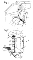
- FIGURE 1 is a perspective view showing a retractor reel in accordance with the invention mounted in a motor car,
- FIGURE 2 is an enlarged perspective view showing a reel in accordance with the invention,
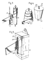
- FIGURE 3 is a diagrammatic view showing the main operative parts of a modified embodiment of the invention,
- FIGURE 4 is a diagrammatic view showing the main parts of another modified embodiment of the invention,
- FIGURE 5 is a diagrammatic view, with parts shown in phantom, of another embodiment of the invention,
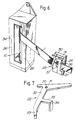
- FIGURE 6 is a diagrammatic exploded view showing yet another embodiment of the invention,
- FIGURE 7 is a perspective view of a lever forming part of the embodiment of Figure 6,
- FIGURE 8 is a perspective exploded view of another embodiment of the invention,and
- FIGURE 9 is a perspective view of the essential parts of another embodiment of the invention.
- Referring initially to Figure 1 of the accompanying drawings, a seat belt of the diagonal-and-lap configuration 1 is mounted in a motor vehicle to protect a person sitting in a seat 2. One end of the belt 1 is connected to an anchor point on the floor of the motor vehicle on one side of the seat (not visible) and the belt then passes across the lap of a person sitting in the seat to a tongue which is to be inserted into a conventional
releasable buckle 3. The belt then passes up across the chest and shoulder of the person wearing the belt to a retractor reel 4 in accordance with the invention which is mounted on the B-post 5 of the motor vehicle at an elevated position just above the shoulder of a person sitting in the seat 2. - As can be seen more clearly from Figure 2 of the drawings the retractor reel comprises a support plate 6 that can be connected to the B-post by means of bolts passing through two
apertures 7 formed in the support plate 6. Of course, the support plate 6 may alternatively be formed integrally with the B-post if desired. At upper and lower positions on the support plate, there are forwardly projecting wings or tabs 8,9. The wings are apertured and receive the ends of ashaft 10 which is thus rotatably mounted, theshaft 10 thus extending substantially vertically between the wings 8 and 9. A cover 11 (shown in phantom in Figure 2) is mounted on the upper wing 8. Ahelical spring 12 is provided within thecover 11 and engages the upper end of theshaft 10 to apply a torque to the shaft. - The lower wing 9 is provided, on its under surface, with a
housing 13. Thehousing 13 contains a mechanism or arrangement which can selectively lock theshaft 10 to prevent rotation of the shaft. Such mechanisms are well known in the seat belt retractor art. The mechanism may include means responsive to a pre-determined vehicle acceleration or deceleration to lock the shaft, or means responsive to a rate of rotation of the shaft, or responsive to a rate of acceleration of the shaft, in excess of a pre-determined limit, to lock the shaft. - The shaft is provided, adjacent its upper end, with a diametrically extending
slot 14 to which is secured one end of the seat belt 1. The belt 1 is wound round or reeled directly on to theshaft 10. The length of theshaft 10 that is exposed to receive the seat belt reeled on to the shaft is at least two times the width of the safety belt, and in this embodiment is several times greater than the width of thewebbing 15 of the safety belt 1. Thus the length of shaft exposed to receive the reeled in safety belt may have a length of two, three or more times the width of the safety belt 1. - The
helical spring 12 is arranged so that it biases the shaft to wind in the safety belt to form a reel of safety belt on theshaft 10. - It will be appreciated that when a safety belt retractor as described above is used, initially the person who is to use the belt will pull a length of belt from the retractor reel, thus rotating the
shaft 10 and tensioning thespring 12. The belt will then be placed in the position in which the belt is to be worn, and will be retained by thebuckle 3. Any slack in the belt will then be released and a length of belt will be withdrawn back into the retractor reel 4 under the effect of thespring 12. Since the belt 1 that is being wound on to theshaft 10 passes over the shoulder of the person wearing the belt, as the slack in the belt is taken up, the belt will adopt the correct position on thevertical shaft 10. - For example, if the person wearing the belt is tall, his shoulder may be substantially aligned with the top of the exposed part of the
vertical shaft 10. Consequently, when the safety belt 1 is wound on to theshaft 10, the safety belt is wound on to only the upper region of the shaft and then extends substantially horizontally to the shoulder of the person wearing the belt. In contrast, if the person wearing the safety belt is short, his shoulder may be aligned with the lower region of the exposed part of theshaft 10. In such a case, when any slack in the safety belt is taken up, the safety belt 1 will wind on to the exposed length of theshaft 10 in the form a spiral, as shown in Figure 2, with the strap emerging from the shaft at a relatively low position, substantially horizontally aligned with the shoulder of the person wearing the belt. Thus again the belt will extend substantially horizontally from the shaft to the shoulder of the person wearing the belt. It will thus be understood that the described arrangement provides an automatic adjusting effect, adjusting the point at which the belt is received on to the shaft. - A further advantage of the described embodiment, when compared with the prior art, is that the retractor reel is located at an elevated position, and consequently the length of safety belt that is exposed and that is available to stretch when a great load is applied to the belt under accident conditions, is less than in the prior art arrangement. Thus in any accident situation the absolute amount of stretch will be less than in the prior art. By way of comparison, the exposed length of belt in a typical arrangement in accordance with the invention will be about 2 metres, giving a total stretch of only 20 cm when the belt is exposed to a load which provides a ten per cent stretch. This may be compared with the 30 cm stretch of the typical prior art arrangement under identical conditions. The difference in stretch of 10 cm may make the difference between life and death for a person restrained by the safety belt.
- Figure 2 illustrates a
spool flange 16 mounted on theshaft 10 adjacent the lower wing 9 carried by the support plate. This serves to minimise any risk of the safety belt 1 from becoming caught on the wing 9, particularly in the region where theshaft 10 passes through the wing 9. It may also be preferred for the outer surface of theshaft 10 to be made to have high friction properties. Thus a sleeve of high friction material may be mounted on the shaft, or the outer surface of the shaft may be roughened or knurled. - Instead of having the belt reeled directly on to the
shaft 14, the belt could instead be reeled on to a spool mounted on a vertical shaft corresponding to theshaft 10. The spool may have an available width which is two or more times the width of the belt. Alternatively the spool may have an available width which is substantially the same as the width of the belt, and the spool may be mounted to effect a sliding movement up and down the shaft over a length equal to at least twice the width of the belt. - In certain circumstances it may be desired for such a spool to be spring biased towards an upper position and indeed it may also be desirable for such a spool to be provided with a releasable mechanism to retain the spool in the upper position. Thus, by utilising such a mechanism, the spool may either self-adjust its height or may be locked in an upper position.
- Further modifications may also be effected to the described embodiment. Figure 3 illustrates such a modified arrangement in which a guide member 17 is provided to guide the safety belt 1 on to the
shaft 10. The guide member defines aslot 18 through which the terminal portion of the safety belt 1 passes. The guide member is mounted for vertical movement up and down a vertical rod 19 which is parallel with the axis of theshaft 10. The guide member may, as with the spool mentioned above, be biased towards an upper position, by a spring, as shown in phantom, and may also be provided with means for selectively retaining the guide member in an upper position. - Figure 4 illustrates a further modified embodiment of the invention in which the
main shaft 10′ is of non-uniform section. Theshaft 10′ is illustrated as being of conical section. This may assist the automatic adjustment function as described above. In the embodiment illustrated in Figure 4 asecond roller 20 is provided which is located adjacent theshaft 10′. Theroller 20 is urged into contact with theshaft 10′ in the direction of thearrows 21 by appropriate pressure applying means, such as springs or the like. This serves to create a "nip" which will help ensure that the safety belt is always reeled neatly on to theshaft 10′ and will help minimise any problem that may arise from the so-called "film spool effect". Such problems may also be overcome by making the cross-section of the exposed region of the shaft on which the reel of safety belt is formed to be non-circular, for example eliptical. - While reference has been made to arrangements in which the shaft may be locked to prevent the withdrawal of belt from the retractor under certain circumstances, it is to be appreciated that alternatively the belt may be directly clamped, or locked in some other way, either in response to a sensor carried within the retractor arrangement, or in response to a signal from a central sensor.
- As has been mentioned above, in certain circumstances it may be desired to retain the safety belt at an upper or elevated position relative to the
shaft 10. Figure 5 illustrates an embodiment of the invention where a facility is provided for performing this function, in the form of ahousing 23 which defines aslot 24 through which the safety belt 1 emerges. Theslot 24 defines one ormore notches 25 in one side wall thereof, dimensioned to receive the safety belt. In the illustrated embodiments thenotch 25 is provided on the left-hand side of theslot 24. It will be understood that when the safety belt runs through the right-hand side of the slot, the safety belt can freely move up and down to effect the self-adjustment procedure described above. However, if the safety belt is moved to the left, as shown in Figure 5, so that the edge of the safety belt 1 is engaged within thenotch 25, then the safety belt will not be free to move downwardly. Thus the safety belt may be retained in a relatively elevated position with reference to theshaft 10. Of course, whilst Figure 5 illustrates only onenotch 25, two or more such notches may be provided. - Figure 6 illustrates yet a further embodiment of the invention in which an arrangement is provided to retain the safety belt in a position adjacent the top of the
shaft 10. In this arrangement twoparallel guides 26 are formed which extend parallel with the axis of theshaft 10. The guides form the two opposed sides of an aperture in the housing of this embodiment of the invention. Acarriage 27 is provided which moves axially along the guides. Thecarriage 27 defines aslot 28 through which the safety belt 1 emerges. In dependence upon the height of the shoulder of the person wearing the seat belt thecarriage 27 moves up and down theguides 26, and theslot 28 is thus located at different positions.Consequently the safety belt 1 is wound on theshaft 10 at different positions. Alever 29 is pivotally mounted on the carriage for rotation about anaxis 30. The lever has afirst arm portion 31 which extends substantially horizontally as shown in Figure 6 and a depending substantially vertically extendingarm portion 32 having an inwardly crankedlower end 33. - If the position of the shoulder of the person wearing the belt is such that, as the belt is withdrawn, the carriage moves upwardly, the belt will engage the
horizontal portion 31 of the lever, which extends over the upper part of theslot 28. Thus the lever is biassed to rotate in a counterclockwise direction. Thelower end 33 of the lever slides against the exterior of the housing until it is alogned with thenotch 34. Thelower end 33 of the dependingarm 32 thus becomes engaged in thenotch 34 provided on the exterior of the housing. The carriage is thus locked in a predetermined upper position and cannot move downwardly unless the lever is released. - However, the depending
arm 32 is provided with a horizontally extendingprojection 35 which carries a rearwardly directedtab 35, the tab passing through anaperture 37 formed in the carriage for this purpose to enable thetab 36 to lie adjacent theshaft 10. The arrangement is such that when a significant proportion of the safety belt 1 has been wound on theshaft 10 with the carriage in the upper-most position, thetab 36 will contact the exterior of the reel of belt formed on theshaft 10, and as further belt is wound on to the shaft, so the lever will be forced to rotate in a clock-wise direction, thus removing the inwardly crankedend 33 of thearm 32 from the notch orrecess 34. The carriage is thus again free to move. - Figure 8 illustrates another embodiment of the invention which is generally similar to the embodiment shown in Figure 7. The portion of the safety belt 1 emerging from the
shaft 10 passes through aslot 38 formed in acarriage 39. The carriage is mounted on the housing for axial movement. A lockingmember 40 is provided which is mounted on a part of the housing, with a hook shapedpart 41 of the locking member passing through anaperture 42. The locking member has an intermediatebent portion 43 and a terminal laterally directedarrangement portion 44 which, when thecarriage 39 is in an elevated position, can engage anabutment 45 formed on the carriage. Theabutment 45 is in the form of a projecting peg. The arrangement is such that when thecarriage 39 is in an elevated position and theengagement portion 44 on the lockingmember 40 has been engaged with theabutment 45, the carriage is retained in that elevated position. Thebent portion 43 extends through theslot 38 to lie adjacent theshaft 10. However, if the safety belt 1 is retracted on to theshaft 10, the exterior of the reel of belt will engage thebent portion 43 of themember 40, thus moving the lockingmember 40, releasing theengagement portion 44 from thedetent 45, thus enabling thecarriage 39 to resume its movement axially, as mentioned above. - It may be possible to provide the carriage with a plurality of spaced apart
detents 45 so that the carr iage may be locked selectively at different positions. - Figure 9 illustrates the essential parts of an alternative embodiment of the invetion in which a
spool 46, which is as wide as the webbing of theseatbelt 15 is mounted for slidable movement on the exposed part of theshaft 10. Thus thespool 46 can rotate relative to the shaft, and can also slide up and down the shaft. The spool is shown being biassed to an upper position by aspring 47 which surrounds the lower part of theshaft 10.
Claims (10)
- A seat-belt retractor assembly, said assembly comprising a support on which is mounted an elongate shaft(10) about which a seat belt(1) may be reeled, means to wind(12) in said seat-belt to form a reel about the shaft, and selectively operable means(13) to prevent the withdrawal of seat-belt from said assembly, the shaft(10) being adapted to be substantially vertical and having an exposed region about which the reel may be formed, the length of the exposed region being significantly greater than the width of the seat-belt so that the seat-belt may be positioned with the part of the belt emerging from the reel having any selected position along said exposed region of the shaft.
- An assembly according to Claim 1 wherein a spool(46) is mounted on said shaft, the spool being movable axially of the shaft(10) along said exposed region and being adapted to have the belt(1) wound on to it.
- An assembly according to Claim 1 wherein the exposed region of the shaft(10) is of non-uniform section being of conical or tapering form, or being of non-round section.
- An assembly according to any one of the preceding Claims wherein a roller(20) is provided, extending substantially parallel with the shaft(10) and being biassed(21) towards the shaft to trap part of the belt(1) between the roller and the shaft.
- An assembly according to any one of the preceding Claims wherein a belt guide(17) is provided which engages and guides the belt(1) on to and from said reel, the guide being mounted for movement in a direction substantially parallel with the axis of the shaft.
- An assembly according to Claim 5 wherein means(29-36) are provided to retain the belt guide in one predetermined position.
- An arrangement according to Claim 6 wherein means(36) are provided to release the means(33,34) which retain the belt guide when a predetermined length of safety-belt has been wound on to said shaft.
- An assembly according to Claim 6 wherein a locking lever(29) is associated with the said guide(27), the locking lever being movable to a position in which movement of the guide is prevented when the guide is at one terminal position, and being moved to a release position in response to a predetermined length of safety-belt being wound on to said shaft.
- An assembly according to any one of Claims 1 to 4, wherein the belt(1) passes, from the shaft(10), through a slot(24), the slot being provided with one or more recesses(25) formed in the side thereof.
- A seat-belt arrangement incorporating a retractor assembly according to any one of the preceding Claims, the retractor being mounted in position with the shaft substantially vertical, and such that when a person who is to wear the belt sits in his seat, the retractor assembly is adjacent the shoulder of that person.
Applications Claiming Priority (2)
| Application Number | Priority Date | Filing Date | Title |
|---|---|---|---|
| GB8723212A GB2210251B (en) | 1987-10-02 | 1987-10-02 | Improvements in or relating to a seat belt retractor |
| GB8723212 | 1987-10-02 |
Publications (2)
| Publication Number | Publication Date |
|---|---|
| EP0335936A1 EP0335936A1 (en) | 1989-10-11 |
| EP0335936B1 true EP0335936B1 (en) | 1993-03-24 |
Family
ID=10624725
Family Applications (1)
| Application Number | Title | Priority Date | Filing Date |
|---|---|---|---|
| EP88908780A Expired - Lifetime EP0335936B1 (en) | 1987-10-02 | 1988-09-30 | A seat belt retractor |
Country Status (6)
| Country | Link |
|---|---|
| US (1) | US4974876A (en) |
| EP (1) | EP0335936B1 (en) |
| AU (1) | AU609896B2 (en) |
| DE (1) | DE3879677T2 (en) |
| GB (1) | GB2210251B (en) |
| WO (1) | WO1989002841A1 (en) |
Cited By (2)
| Publication number | Priority date | Publication date | Assignee | Title |
|---|---|---|---|---|
| WO2013104398A1 (en) * | 2012-01-13 | 2013-07-18 | Daimler Ag | Rolling-up device for rolling up a belt and safety belt system |
| CN106064602A (en) * | 2015-04-24 | 2016-11-02 | 福特全球技术公司 | Height adjuster with return spring system and method |
Families Citing this family (15)
| Publication number | Priority date | Publication date | Assignee | Title |
|---|---|---|---|---|
| US5590907A (en) * | 1995-10-10 | 1997-01-07 | Vehicle Safety Systems, Inc. | Seat belt positioning device and system |
| US5704645A (en) * | 1996-03-28 | 1998-01-06 | Ford Global Technologies, Inc. | Occupant restraint system |
| US5733013A (en) * | 1996-11-19 | 1998-03-31 | Trw Vehicle Safety Systems Inc | Vehicle occupant restraint apparatus |
| SE508109C2 (en) * | 1996-12-20 | 1998-08-31 | Saab Automobile | Device for a belt-shaped seat belt |
| US5755235A (en) * | 1997-02-04 | 1998-05-26 | Trw Vehicle Safety Systems Inc. | Prisoner restraint apparatus for a law enforcement vehicle |
| US5806891A (en) * | 1997-05-23 | 1998-09-15 | Pokhis; Naum | Safety belts for motor vehicles |
| US6592149B2 (en) | 2000-11-28 | 2003-07-15 | Paris E. Sessoms | Positioning devices for vehicle occupant restraints |
| EP1316484B1 (en) * | 2001-11-28 | 2011-12-21 | Volvo Car Corporation | Mounting system for safety belt system |
| US7140571B2 (en) | 2003-06-11 | 2006-11-28 | Autoliv, Asp, Inc. | Electric seat belt retractor system |
| US6935590B2 (en) | 2003-05-19 | 2005-08-30 | Autoliv Asp, Inc. | Sensor for a feedback control system |
| DE60321153D1 (en) * | 2003-07-11 | 2008-07-03 | Ford Global Tech Llc | Sischerheitsgurtumlenkanordnung |
| DE102007017242A1 (en) * | 2007-04-12 | 2008-10-16 | Dr. Ing. H.C. F. Porsche Aktiengesellschaft | Method and device for roll stabilization of a motor vehicle |
| US7905233B2 (en) * | 2007-04-12 | 2011-03-15 | Stryker Corporation | Patient restraint |
| US20160311396A1 (en) * | 2015-04-24 | 2016-10-27 | GM Global Technology Operations LLC | Belt buckle anchor for thin seats |
| CN107595354A (en) * | 2017-09-20 | 2018-01-19 | 范海盟 | A kind of otch protector of Implanted cardiac pacemaker |
Family Cites Families (11)
| Publication number | Priority date | Publication date | Assignee | Title |
|---|---|---|---|---|
| SE327915B (en) * | 1964-09-21 | 1970-08-31 | H Karlsson | |
| US3488090A (en) * | 1968-06-19 | 1970-01-06 | Dwaine C Douglas | Passenger harness |
| SE388128B (en) * | 1973-10-30 | 1976-09-27 | H I R Karlsson | DEVICE FOR A SPRING-AFFECTED, REVERSIBLE ROBBERABLE BODY |
| US3869097A (en) * | 1974-01-04 | 1975-03-04 | Ford Motor Co | Webbing slot for seat belt retractor housing |
| DE2614472C2 (en) * | 1976-04-03 | 1980-02-14 | Graenges - Fahrzeugtechnik Gmbh, 2400 Luebeck | Belt retractors for seat belts |
| GB1577951A (en) * | 1976-04-26 | 1980-10-29 | Coenen Benelux Bv | Safety belt |
| DE2618255A1 (en) * | 1976-04-27 | 1977-11-17 | Daimler Benz Ag | Rattling prevention on seat belt spools - uses predetermined surplus seat belt length to compensate free play on spool |
| DE2720789A1 (en) * | 1977-05-09 | 1978-11-23 | Zinser Maschinenbau Kg | Automatically height-adjusting seat belt anchor point - is attached to spring loaded movable strand of belt and roller assembly |
| DE3214712C2 (en) * | 1982-04-21 | 1986-10-16 | Bayerische Motoren Werke AG, 8000 München | Adjustment device for a point of attachment or deflection of a seat belt |
| DE3514980A1 (en) * | 1984-05-28 | 1985-11-28 | TRW Repa GmbH, 7071 Alfdorf | FITTING FOR A SAFETY BELT FOR MOTOR VEHICLES |
| US4765651A (en) * | 1986-05-13 | 1988-08-23 | American Safety Equipment Corporation | Adjustable anchoring slide block assembly |
-
1987
- 1987-10-02 GB GB8723212A patent/GB2210251B/en not_active Revoked
-
1988
- 1988-09-30 WO PCT/SE1988/000507 patent/WO1989002841A1/en active IP Right Grant
- 1988-09-30 US US07/382,649 patent/US4974876A/en not_active Expired - Lifetime
- 1988-09-30 DE DE8888908780T patent/DE3879677T2/en not_active Expired - Fee Related
- 1988-09-30 EP EP88908780A patent/EP0335936B1/en not_active Expired - Lifetime
- 1988-09-30 AU AU25338/88A patent/AU609896B2/en not_active Ceased
Cited By (3)
| Publication number | Priority date | Publication date | Assignee | Title |
|---|---|---|---|---|
| WO2013104398A1 (en) * | 2012-01-13 | 2013-07-18 | Daimler Ag | Rolling-up device for rolling up a belt and safety belt system |
| CN106064602A (en) * | 2015-04-24 | 2016-11-02 | 福特全球技术公司 | Height adjuster with return spring system and method |
| CN106064602B (en) * | 2015-04-24 | 2020-04-10 | 福特全球技术公司 | Seat belt height adjuster system and method |
Also Published As
| Publication number | Publication date |
|---|---|
| EP0335936A1 (en) | 1989-10-11 |
| GB8723212D0 (en) | 1987-11-04 |
| DE3879677D1 (en) | 1993-04-29 |
| GB2210251B (en) | 1991-10-30 |
| AU2533888A (en) | 1989-04-18 |
| AU609896B2 (en) | 1991-05-09 |
| US4974876A (en) | 1990-12-04 |
| DE3879677T2 (en) | 1993-07-01 |
| GB2210251A (en) | 1989-06-07 |
| WO1989002841A1 (en) | 1989-04-06 |
Similar Documents
| Publication | Publication Date | Title |
|---|---|---|
| EP0335936B1 (en) | A seat belt retractor | |
| US3918658A (en) | Seat belt retractor having inertial device activated by two stimuli | |
| US6773075B2 (en) | Four point seat belt restraint system | |
| US3847434A (en) | Vehicle occupant restraint system | |
| US5350196A (en) | Retraction locking device for restraining belt | |
| US7571934B2 (en) | Seat belt system for adults and children | |
| US4610480A (en) | Built-in type safety seat belt system for reclining vehicle seat | |
| EP0764097B1 (en) | Vehicle safety restraints | |
| US4349216A (en) | Floating lock mount for a seat belt retractor | |
| US7360795B2 (en) | Torsion bar load limiter and pretensioner for seat belt system | |
| SE468797B (en) | QUARHALLING SYSTEM FOR A SAFETY BELOW DRIVING IN VEHICLES | |
| US3942740A (en) | Safety belt retractor assembly | |
| US6508500B2 (en) | Integrated seat belt and seat support | |
| US4583762A (en) | Safety belt for motor vehicles | |
| EP1324901B1 (en) | A safety-belt arrangement | |
| WO2005118330A2 (en) | A seat belt arrangement | |
| GB1601104A (en) | Safety restraint apparatus | |
| US4087118A (en) | Safety seat belt system | |
| US4359237A (en) | Static belt loop snubber system | |
| US3744732A (en) | Vehicle seat belts and harnesses | |
| US4213651A (en) | Seatbelt system | |
| US5924729A (en) | Seat belt webbing energy management device | |
| US3999722A (en) | Safety belt retractor with dual sensitive, commonly mounted, actuating mechanism | |
| US4357035A (en) | Flexible belt positioning arm | |
| US5074589A (en) | Automatic seat belt |
Legal Events
| Date | Code | Title | Description |
|---|---|---|---|
| PUAI | Public reference made under article 153(3) epc to a published international application that has entered the european phase |
Free format text: ORIGINAL CODE: 0009012 |
|
| 17P | Request for examination filed |
Effective date: 19890621 |
|
| AK | Designated contracting states |
Kind code of ref document: A1 Designated state(s): DE FR GB IT SE |
|
| 17Q | First examination report despatched |
Effective date: 19910805 |
|
| GRAA | (expected) grant |
Free format text: ORIGINAL CODE: 0009210 |
|
| AK | Designated contracting states |
Kind code of ref document: B1 Designated state(s): DE FR GB IT SE |
|
| PG25 | Lapsed in a contracting state [announced via postgrant information from national office to epo] |
Ref country code: IT Free format text: LAPSE BECAUSE OF FAILURE TO SUBMIT A TRANSLATION OF THE DESCRIPTION OR TO PAY THE FEE WITHIN THE PRE;WARNING: LAPSES OF ITALIAN PATENTS WITH EFFECTIVE DATE BEFORE 2007 MAY HAVE OCCURRED AT ANY TIME BEFORE 2007. THE CORRECT EFFECTIVE DATE MAY BE DIFFERENT FROM THE ONE RECORDED.SCRIBED TIME-LIMIT Effective date: 19930324 Ref country code: SE Effective date: 19930324 |
|
| REF | Corresponds to: |
Ref document number: 3879677 Country of ref document: DE Date of ref document: 19930429 |
|
| ET | Fr: translation filed | ||
| PLBE | No opposition filed within time limit |
Free format text: ORIGINAL CODE: 0009261 |
|
| STAA | Information on the status of an ep patent application or granted ep patent |
Free format text: STATUS: NO OPPOSITION FILED WITHIN TIME LIMIT |
|
| 26N | No opposition filed | ||
| REG | Reference to a national code |
Ref country code: GB Ref legal event code: IF02 |
|
| PGFP | Annual fee paid to national office [announced via postgrant information from national office to epo] |
Ref country code: FR Payment date: 20030909 Year of fee payment: 16 |
|
| PGFP | Annual fee paid to national office [announced via postgrant information from national office to epo] |
Ref country code: GB Payment date: 20030924 Year of fee payment: 16 |
|
| PGFP | Annual fee paid to national office [announced via postgrant information from national office to epo] |
Ref country code: DE Payment date: 20031009 Year of fee payment: 16 |
|
| PG25 | Lapsed in a contracting state [announced via postgrant information from national office to epo] |
Ref country code: GB Free format text: LAPSE BECAUSE OF NON-PAYMENT OF DUE FEES Effective date: 20040930 |
|
| PG25 | Lapsed in a contracting state [announced via postgrant information from national office to epo] |
Ref country code: DE Free format text: LAPSE BECAUSE OF NON-PAYMENT OF DUE FEES Effective date: 20050401 |
|
| GBPC | Gb: european patent ceased through non-payment of renewal fee |
Effective date: 20040930 |
|
| PG25 | Lapsed in a contracting state [announced via postgrant information from national office to epo] |
Ref country code: FR Free format text: LAPSE BECAUSE OF NON-PAYMENT OF DUE FEES Effective date: 20050531 |
|
| REG | Reference to a national code |
Ref country code: FR Ref legal event code: ST |