EP0335626B1 - Leistungsversorgungsschaltung - Google Patents
Leistungsversorgungsschaltung Download PDFInfo
- Publication number
- EP0335626B1 EP0335626B1 EP89302989A EP89302989A EP0335626B1 EP 0335626 B1 EP0335626 B1 EP 0335626B1 EP 89302989 A EP89302989 A EP 89302989A EP 89302989 A EP89302989 A EP 89302989A EP 0335626 B1 EP0335626 B1 EP 0335626B1
- Authority
- EP
- European Patent Office
- Prior art keywords
- circuit
- load
- transformer
- voltage regulator
- thyristor
- Prior art date
- Legal status (The legal status is an assumption and is not a legal conclusion. Google has not performed a legal analysis and makes no representation as to the accuracy of the status listed.)
- Expired - Lifetime
Links
- 238000004804 winding Methods 0.000 claims description 12
- 230000004075 alteration Effects 0.000 description 1
- 238000010586 diagram Methods 0.000 description 1
- 238000010304 firing Methods 0.000 description 1
- 238000010438 heat treatment Methods 0.000 description 1
- 238000010079 rubber tapping Methods 0.000 description 1
Images
Classifications
-
- H—ELECTRICITY
- H02—GENERATION; CONVERSION OR DISTRIBUTION OF ELECTRIC POWER
- H02M—APPARATUS FOR CONVERSION BETWEEN AC AND AC, BETWEEN AC AND DC, OR BETWEEN DC AND DC, AND FOR USE WITH MAINS OR SIMILAR POWER SUPPLY SYSTEMS; CONVERSION OF DC OR AC INPUT POWER INTO SURGE OUTPUT POWER; CONTROL OR REGULATION THEREOF
- H02M1/00—Details of apparatus for conversion
- H02M1/12—Arrangements for reducing harmonics from AC input or output
-
- H—ELECTRICITY
- H02—GENERATION; CONVERSION OR DISTRIBUTION OF ELECTRIC POWER
- H02M—APPARATUS FOR CONVERSION BETWEEN AC AND AC, BETWEEN AC AND DC, OR BETWEEN DC AND DC, AND FOR USE WITH MAINS OR SIMILAR POWER SUPPLY SYSTEMS; CONVERSION OF DC OR AC INPUT POWER INTO SURGE OUTPUT POWER; CONTROL OR REGULATION THEREOF
- H02M5/00—Conversion of AC power input into AC power output, e.g. for change of voltage, for change of frequency, for change of number of phases
- H02M5/02—Conversion of AC power input into AC power output, e.g. for change of voltage, for change of frequency, for change of number of phases without intermediate conversion into DC
- H02M5/04—Conversion of AC power input into AC power output, e.g. for change of voltage, for change of frequency, for change of number of phases without intermediate conversion into DC by static converters
- H02M5/22—Conversion of AC power input into AC power output, e.g. for change of voltage, for change of frequency, for change of number of phases without intermediate conversion into DC by static converters using discharge tubes with control electrode or semiconductor devices with control electrode
- H02M5/25—Conversion of AC power input into AC power output, e.g. for change of voltage, for change of frequency, for change of number of phases without intermediate conversion into DC by static converters using discharge tubes with control electrode or semiconductor devices with control electrode using devices of a thyratron or thyristor type requiring extinguishing means
- H02M5/257—Conversion of AC power input into AC power output, e.g. for change of voltage, for change of frequency, for change of number of phases without intermediate conversion into DC by static converters using discharge tubes with control electrode or semiconductor devices with control electrode using devices of a thyratron or thyristor type requiring extinguishing means using semiconductor devices only
- H02M5/2573—Conversion of AC power input into AC power output, e.g. for change of voltage, for change of frequency, for change of number of phases without intermediate conversion into DC by static converters using discharge tubes with control electrode or semiconductor devices with control electrode using devices of a thyratron or thyristor type requiring extinguishing means using semiconductor devices only with control circuit
Definitions
- the invention relates to electrical power supply circuits.
- the present invention has been developed to control the power being supplied to an ohmic heater, such as described for example in UK Patent Specification A 2068200, but can be used for supplying a wide variety of electrical loads. In many cases the supply must be controlled to respond quickly and evenly to changes and also to comply with various regulations of power utility companies so as not to interfere with the power being supplied to other consumers from the same mains supply by the generation of unacceptable harmonics in the mains power supply.
- an alternating current power supply circuit for a variable electrical load which circuit comprises a power transformer (10) having a secondary winding for connection to the load, a controllable thyristor network (15) for supplying the primary winding, and a load responsive circuit (16) arranged to provide control signals to control operation of the thyristor network (15), characterised in that there is provided an adjustable voltage regulator (13, 14) connected to the primary winding of the transformer (10), and in that the load responsive circuit (16) is also arranged to provide control signals to adjust the voltage regulator (13, 14) in a manner to tend to maintain the thyristors of the said thyristor network (15) in their conductive states for a predetermined maximum period of each cycle of respective half-wave voltage of the incoming supply (12) so that overall inherent harmonic reflections are kept to a minimum.
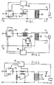
- a power transformer 10 has terminals 11 on its secondary winding for connection to a variable electrical load.
- the primary winding is connected at one end to a mains supply terminal 12 and its other end is connected to a movable sliding contact 13 on a voltage regulator 14, in the form of an autotransformer arrangement.
- the regulator 14 is connected between the output side of a thyristor network 15 and the mains supply terminal 12.
- a load responsive circuit 16 is connected to receive signals from a load sensing transducer 17 and arranged in use in response to signals from the transducer to vary the operation of the thyristors and simultaneously to adjust the position of the contact 13.
- the described circuit is arranged to vary the supply to alter the output of the transformer 10 as the load or the requirement for supplying the load vary.
- the flow rate of the medium being processed and its temperatures are continuously monitored by one or more transducers and the output of the transformer 10 varied to keep the effective amount of heating of the medium within a desired predetermined range.
- the overall control made possible by use of the described circuit enables the inherent rapid response of the thyristor circuit to be used to make rapid adjustments for any rapidly required changes in the power output of the transformer 10. This is in contrast, certainly, to the inherently much slower response of the described regulator 14 which incorporates mechanical moving parts.
- the thyristors can be maintained to turn on always in each cycle close to the zero crossings of the mains voltage so that resultant harmonics generated in the system are always of low power.
- the thyristors must always be turned on somewhat after the crossing, even when at supposed optimum adjustment for any load, to allow the control circuit to respond to all changes in the load, that is changes in both directions, as required.
- control circuit is arranged to simultaneously and continuously control the operation of the thyristor circuit 15 and the movement of the contact 13 to achieve the best conditions for minimum power harmonic generation and maximum power factor. This can be achieved for example by making, when necessary immediate, changes to the output of the transformer 10 using the facility of rapidly changing the effecting mark space ratio of conduction of the thyristors.
- control circuit is arranged to also adjust, but inherently more slowly, the regulator 14 to alter the primary voltage in response to this load change while controlling the mark space ratio to compensate for the regulator alterations as the contact 13 is moved.
- the load reduces the power can be rapidly reduced by delaying the switch- on of the thyristors and then as the regulator reduces the voltage the thyristors are progressively switched on earlier until the optimum balance is achieved for the new lower load conditions.
- the supply circuit is generally the same and controlled in a similar manner to the supply circuit in Figure 1 except the voltage regulator is in the form of an auxiliary transformer 20 supplied by a second thyristor network 21.
- the load sensing circuit in Figure 2 controls the operation of both thyristor networks 15 and 21 simultaneously.
- the supply circuit is generally the same and controlled in a similar manner to the supply circuit in figure 1 and the auxiliary transformer 20 and thyristor network 21 as in fig 2, but in this circuit the main transformer has secondary taps and a tapping switch. The taps are arranged for load impedance ranges.
- the auxiliary transformer and its thyristor primary control are considerably reduced in rating and hence size because the range of control can be much reduced by selecting the correct tap in anticipation or precalibration of the overall load to be supplied by the circuit.
Landscapes
- Engineering & Computer Science (AREA)
- Power Engineering (AREA)
- Control Of Electrical Variables (AREA)
- Apparatus For Radiation Diagnosis (AREA)
- Air Bags (AREA)
- Input Circuits Of Receivers And Coupling Of Receivers And Audio Equipment (AREA)
- Electrical Discharge Machining, Electrochemical Machining, And Combined Machining (AREA)
- Fittings On The Vehicle Exterior For Carrying Loads, And Devices For Holding Or Mounting Articles (AREA)
- Oscillators With Electromechanical Resonators (AREA)
Claims (4)
- Schaltungsanordnung zur Wechselstrom-Versorgung einer variablen elektrischen Last mit einem Leistungstransformator (10), dessen Sekundärwicklung mit der Last zu verbinden ist, ferner mit einer steuerbaren Thyristor-Schaltung (15) die an der Primärwicklung des Transformators (10) liegt und mit einem lastabhängigen Steuerkreis (16) zur Erzeugung der Signale zur Ansteuerung der Thyristor-Schaltung (15),
dadurch gekennzeichnet,
daß der Primärwicklung des Transformators (10) ein justierbarer Spannungsregler (13) vorgeschaltet ist und der lastabhängige Steuerkreis (16) mittels Steuersignalen diesen Spannungsregler (13,14) derart einstellt, daß die Thyristoren der Thyristor-Schaltung (15) jeweils für eine vorbestimmte, maximale Dauer eines jeden Zyklus der jeweiligen Halbwellen-Spannung der Wechselspannungsquelle (12) im leitenden Zustand bleiben, womit die Spannungsoberwellen insgesamt auf einem Minimum gehalten werden. - Schaltungsanordnung nach Anspruch 1,
dadurch gekennzeichnet,
daß der Spannungsregler (14) einen Gleitkontakt (13) aufweist. - Schaltungsanordnung nach Anspruch 1,
dadurch gekennzeichnet,
daß der Spannungsregler (14) einen Hilfstransformator (20) umfaßt, der über eine zweite Thyristor-Schaltung (21) versorgt ist. - Schaltungsanordnung nach einem der Ansprüche 1 bis 3,
dadurch gekennzeichnet,
daß der Leistungstransformator (10) mit einer gestuften, angezapften Sekundärwicklung ausgestattet ist.
Priority Applications (1)
| Application Number | Priority Date | Filing Date | Title |
|---|---|---|---|
| AT89302989T ATE94005T1 (de) | 1988-03-29 | 1989-03-28 | Leistungsversorgungsschaltung. |
Applications Claiming Priority (2)
| Application Number | Priority Date | Filing Date | Title |
|---|---|---|---|
| GB8807529 | 1988-03-29 | ||
| GB8807529A GB2216348B (en) | 1988-03-29 | 1988-03-29 | Power supply circuit |
Publications (3)
| Publication Number | Publication Date |
|---|---|
| EP0335626A2 EP0335626A2 (de) | 1989-10-04 |
| EP0335626A3 EP0335626A3 (en) | 1990-03-14 |
| EP0335626B1 true EP0335626B1 (de) | 1993-09-01 |
Family
ID=10634342
Family Applications (1)
| Application Number | Title | Priority Date | Filing Date |
|---|---|---|---|
| EP89302989A Expired - Lifetime EP0335626B1 (de) | 1988-03-29 | 1989-03-28 | Leistungsversorgungsschaltung |
Country Status (6)
| Country | Link |
|---|---|
| US (1) | US4965508A (de) |
| EP (1) | EP0335626B1 (de) |
| JP (1) | JPH0215317A (de) |
| AT (1) | ATE94005T1 (de) |
| DE (1) | DE68908747T2 (de) |
| GB (1) | GB2216348B (de) |
Families Citing this family (14)
| Publication number | Priority date | Publication date | Assignee | Title |
|---|---|---|---|---|
| DE4205252A1 (de) * | 1992-02-21 | 1993-08-26 | Hella Kg Hueck & Co | Einrichtung zum betreiben von lasten an wechselspannungsquellen |
| HU211048B (en) * | 1992-05-22 | 1995-12-28 | Deltronic Ipari Elektronikus K | Connection arrangement to compensate loss of voltage in power supply cables as well as to reduce harmonic component content of current |
| US5515262A (en) * | 1992-10-21 | 1996-05-07 | Hitran Corporation | Variable inductance current limiting reactor |
| EP0737333B1 (de) * | 1993-12-23 | 1997-09-03 | Siemens Aktiengesellschaft | Konstantstromregler mit aufspanntransformator |
| US5537026A (en) * | 1995-04-26 | 1996-07-16 | Emerson Electric Co. | Method and apparatus for power controller operation using master and slave firing units |
| US5825164A (en) * | 1995-12-21 | 1998-10-20 | Adb-Alnaco, Inc. | Inductance controller with load regulator |
| GB9701066D0 (en) * | 1997-01-20 | 1997-03-12 | Induced Energy Ltd | Induction heating apparatus |
| US5838144A (en) * | 1997-05-07 | 1998-11-17 | York International Corporation | Solid state, reduced voltage motor starter enabling equalized input/output volt-amp ratings |
| US5923143A (en) * | 1998-03-20 | 1999-07-13 | York International Corporation | Solid state motor starter with energy recovery |
| WO2001093400A1 (en) * | 2000-06-01 | 2001-12-06 | Powertec International | Line side power and energy management system and methods |
| KR20030080677A (ko) * | 2002-04-10 | 2003-10-17 | 손순향 | 가정용 전력조절 절전 장치 |
| CN100345074C (zh) * | 2002-06-19 | 2007-10-24 | 沈阳新松机器人自动化股份有限公司 | 一种数字式交流恒流源 |
| US20050068013A1 (en) * | 2003-09-30 | 2005-03-31 | Scoggins Robert L. | Apparatus and methods for power regulation of electrical loads to provide reduction in power consumption with reversing contactors |
| RU2613340C2 (ru) * | 2015-08-19 | 2017-03-16 | Борис Алексеевич Аржанников | Устройство для регулирования напряжения и способ его регулирования |
Family Cites Families (8)
| Publication number | Priority date | Publication date | Assignee | Title |
|---|---|---|---|---|
| NL264420A (de) * | 1960-05-06 | |||
| US3287624A (en) * | 1963-10-22 | 1966-11-22 | Sinclair Research Inc | Tap changing transformer voltage regulating system |
| US3601686A (en) * | 1968-09-26 | 1971-08-24 | Lambda Electronics Corp | Ac regulator employing a control rectifier switching circuit |
| US4103324A (en) * | 1976-12-22 | 1978-07-25 | Airco, Inc. | Saturable reactor-type power supply |
| DE2940172A1 (de) * | 1979-10-04 | 1981-04-16 | Fried. Krupp Gmbh, 4300 Essen | Batterieladegeraet |
| US4286207A (en) * | 1980-04-14 | 1981-08-25 | Westinghouse Electric Corp. | High-power AC voltage stabilizer |
| US4454466A (en) * | 1982-11-29 | 1984-06-12 | Control Data Corporation | Power supply having automatically varied primary turns |
| JPS62213575A (ja) * | 1986-03-13 | 1987-09-19 | Nisshin Haiboruteeji Kk | 高電圧発生装置 |
-
1988
- 1988-03-29 GB GB8807529A patent/GB2216348B/en not_active Expired - Lifetime
-
1989
- 1989-03-23 US US07/327,528 patent/US4965508A/en not_active Expired - Fee Related
- 1989-03-28 DE DE89302989T patent/DE68908747T2/de not_active Expired - Fee Related
- 1989-03-28 JP JP1076412A patent/JPH0215317A/ja active Pending
- 1989-03-28 EP EP89302989A patent/EP0335626B1/de not_active Expired - Lifetime
- 1989-03-28 AT AT89302989T patent/ATE94005T1/de not_active IP Right Cessation
Also Published As
| Publication number | Publication date |
|---|---|
| US4965508A (en) | 1990-10-23 |
| DE68908747D1 (de) | 1993-10-07 |
| GB2216348B (en) | 1992-03-25 |
| EP0335626A3 (en) | 1990-03-14 |
| JPH0215317A (ja) | 1990-01-19 |
| EP0335626A2 (de) | 1989-10-04 |
| DE68908747T2 (de) | 1994-04-14 |
| ATE94005T1 (de) | 1993-09-15 |
| GB2216348A (en) | 1989-10-04 |
| GB8807529D0 (en) | 1988-05-05 |
Similar Documents
| Publication | Publication Date | Title |
|---|---|---|
| US4965508A (en) | Power supply circuit having controllable thyristor network and adjustable voltage regulator | |
| KR100390885B1 (ko) | 파워흐름제어기 | |
| US4630220A (en) | Voltage controller | |
| US3936727A (en) | High speed control of reactive power for voltage stabilization in electric power systems | |
| US4353024A (en) | Control for VAR generator with deadband | |
| US4320245A (en) | Process and apparatus for arc control in arc furnaces | |
| US5900723A (en) | Voltage based VAR compensation system | |
| US4168477A (en) | Electric regulators | |
| CA2096559A1 (en) | Resonant Unity Power Factor Converter | |
| CA2259055A1 (en) | Load power reduction control and supply system | |
| US3821456A (en) | Power control means for a single phase induction melting or heating furnace | |
| US5990667A (en) | Regulator with asymmetrical voltage increase/decrease capability for utility system | |
| US4634958A (en) | Transformer utilizing selectively loaded reactance to control power transfer | |
| US3938031A (en) | Adjustable voltage power supply | |
| US4430607A (en) | Circuit arrangement | |
| US3601686A (en) | Ac regulator employing a control rectifier switching circuit | |
| GB2043971A (en) | Voltage regulators | |
| WO2013079962A2 (en) | Apparatus for controlling the voltage in an alternating current electricity supply | |
| US3536817A (en) | Electric furnace regulation system | |
| US5757176A (en) | Method and system for controlling output current of a large, low-voltage, DC power supply and obtaining diagnostic information from the operation thereof | |
| US2208182A (en) | Electric power transmission system | |
| CA1037115A (en) | Apparatus for stabilization of electrical power supply mains | |
| RU2245600C1 (ru) | Устройство для ступенчатого регулирования переменного напряжения | |
| US3778699A (en) | Resonant type current regulator providing a continuous regulation | |
| GB2596791A (en) | Resistive liquid heater |
Legal Events
| Date | Code | Title | Description |
|---|---|---|---|
| PUAI | Public reference made under article 153(3) epc to a published international application that has entered the european phase |
Free format text: ORIGINAL CODE: 0009012 |
|
| AK | Designated contracting states |
Kind code of ref document: A2 Designated state(s): AT BE CH DE ES FR GB GR IT LI LU NL SE |
|
| PUAL | Search report despatched |
Free format text: ORIGINAL CODE: 0009013 |
|
| AK | Designated contracting states |
Kind code of ref document: A3 Designated state(s): AT BE CH DE ES FR GB GR IT LI LU NL SE |
|
| 17P | Request for examination filed |
Effective date: 19900523 |
|
| 17Q | First examination report despatched |
Effective date: 19920609 |
|
| RAP1 | Party data changed (applicant data changed or rights of an application transferred) |
Owner name: APV UK LIMITED |
|
| RBV | Designated contracting states (corrected) |
Designated state(s): AT BE CH DE ES FR GR IT LI LU NL SE |
|
| GRAA | (expected) grant |
Free format text: ORIGINAL CODE: 0009210 |
|
| AK | Designated contracting states |
Kind code of ref document: B1 Designated state(s): AT BE CH DE ES FR GR IT LI LU NL SE |
|
| PG25 | Lapsed in a contracting state [announced via postgrant information from national office to epo] |
Ref country code: SE Effective date: 19930901 Ref country code: LI Effective date: 19930901 Ref country code: GR Free format text: LAPSE BECAUSE OF FAILURE TO SUBMIT A TRANSLATION OF THE DESCRIPTION OR TO PAY THE FEE WITHIN THE PRESCRIBED TIME-LIMIT Effective date: 19930901 Ref country code: ES Free format text: THE PATENT HAS BEEN ANNULLED BY A DECISION OF A NATIONAL AUTHORITY Effective date: 19930901 Ref country code: CH Effective date: 19930901 Ref country code: BE Effective date: 19930901 Ref country code: AT Effective date: 19930901 |
|
| REF | Corresponds to: |
Ref document number: 94005 Country of ref document: AT Date of ref document: 19930915 Kind code of ref document: T |
|
| ITF | It: translation for a ep patent filed | ||
| REF | Corresponds to: |
Ref document number: 68908747 Country of ref document: DE Date of ref document: 19931007 |
|
| ET | Fr: translation filed | ||
| REG | Reference to a national code |
Ref country code: CH Ref legal event code: PL |
|
| PG25 | Lapsed in a contracting state [announced via postgrant information from national office to epo] |
Ref country code: LU Free format text: LAPSE BECAUSE OF NON-PAYMENT OF DUE FEES Effective date: 19940331 |
|
| PLBE | No opposition filed within time limit |
Free format text: ORIGINAL CODE: 0009261 |
|
| STAA | Information on the status of an ep patent application or granted ep patent |
Free format text: STATUS: NO OPPOSITION FILED WITHIN TIME LIMIT |
|
| 26N | No opposition filed | ||
| PGFP | Annual fee paid to national office [announced via postgrant information from national office to epo] |
Ref country code: DE Payment date: 19980220 Year of fee payment: 10 |
|
| PGFP | Annual fee paid to national office [announced via postgrant information from national office to epo] |
Ref country code: FR Payment date: 19980330 Year of fee payment: 10 |
|
| PGFP | Annual fee paid to national office [announced via postgrant information from national office to epo] |
Ref country code: NL Payment date: 19980331 Year of fee payment: 10 |
|
| PG25 | Lapsed in a contracting state [announced via postgrant information from national office to epo] |
Ref country code: NL Free format text: LAPSE BECAUSE OF NON-PAYMENT OF DUE FEES Effective date: 19991001 |
|
| PG25 | Lapsed in a contracting state [announced via postgrant information from national office to epo] |
Ref country code: FR Free format text: LAPSE BECAUSE OF NON-PAYMENT OF DUE FEES Effective date: 19991130 |
|
| NLV4 | Nl: lapsed or anulled due to non-payment of the annual fee |
Effective date: 19991001 |
|
| REG | Reference to a national code |
Ref country code: FR Ref legal event code: ST |
|
| PG25 | Lapsed in a contracting state [announced via postgrant information from national office to epo] |
Ref country code: DE Free format text: LAPSE BECAUSE OF NON-PAYMENT OF DUE FEES Effective date: 20000101 |
|
| PG25 | Lapsed in a contracting state [announced via postgrant information from national office to epo] |
Ref country code: IT Free format text: LAPSE BECAUSE OF NON-PAYMENT OF DUE FEES;WARNING: LAPSES OF ITALIAN PATENTS WITH EFFECTIVE DATE BEFORE 2007 MAY HAVE OCCURRED AT ANY TIME BEFORE 2007. THE CORRECT EFFECTIVE DATE MAY BE DIFFERENT FROM THE ONE RECORDED. Effective date: 20050328 |