EP0335591A1 - Leitpfosten - Google Patents
Leitpfosten Download PDFInfo
- Publication number
- EP0335591A1 EP0335591A1 EP89302906A EP89302906A EP0335591A1 EP 0335591 A1 EP0335591 A1 EP 0335591A1 EP 89302906 A EP89302906 A EP 89302906A EP 89302906 A EP89302906 A EP 89302906A EP 0335591 A1 EP0335591 A1 EP 0335591A1
- Authority
- EP
- European Patent Office
- Prior art keywords
- base
- marker post
- section
- post
- marker
- Prior art date
- Legal status (The legal status is an assumption and is not a legal conclusion. Google has not performed a legal analysis and makes no representation as to the accuracy of the status listed.)
- Withdrawn
Links
- 239000003550 marker Substances 0.000 title claims abstract description 19
- 239000000463 material Substances 0.000 claims description 6
- 239000004033 plastic Substances 0.000 claims description 3
- 229920003023 plastic Polymers 0.000 claims description 3
- 239000002184 metal Substances 0.000 abstract description 6
- 238000009434 installation Methods 0.000 description 4
- OKTJSMMVPCPJKN-UHFFFAOYSA-N Carbon Chemical compound [C] OKTJSMMVPCPJKN-UHFFFAOYSA-N 0.000 description 2
- 229910052799 carbon Inorganic materials 0.000 description 2
- 229920002457 flexible plastic Polymers 0.000 description 2
- 229920002430 Fibre-reinforced plastic Polymers 0.000 description 1
- 239000004743 Polypropylene Substances 0.000 description 1
- 230000037237 body shape Effects 0.000 description 1
- 238000005553 drilling Methods 0.000 description 1
- 230000005611 electricity Effects 0.000 description 1
- 239000000835 fiber Substances 0.000 description 1
- 239000011151 fibre-reinforced plastic Substances 0.000 description 1
- 239000011521 glass Substances 0.000 description 1
- 238000003780 insertion Methods 0.000 description 1
- 230000037431 insertion Effects 0.000 description 1
- 238000000034 method Methods 0.000 description 1
- 238000012986 modification Methods 0.000 description 1
- 230000004048 modification Effects 0.000 description 1
- -1 polypropylene Polymers 0.000 description 1
- 229920001155 polypropylene Polymers 0.000 description 1
- XLYOFNOQVPJJNP-UHFFFAOYSA-N water Substances O XLYOFNOQVPJJNP-UHFFFAOYSA-N 0.000 description 1
Images

Classifications
-
- E—FIXED CONSTRUCTIONS
- E01—CONSTRUCTION OF ROADS, RAILWAYS, OR BRIDGES
- E01F—ADDITIONAL WORK, SUCH AS EQUIPPING ROADS OR THE CONSTRUCTION OF PLATFORMS, HELICOPTER LANDING STAGES, SIGNS, SNOW FENCES, OR THE LIKE
- E01F9/00—Arrangement of road signs or traffic signals; Arrangements for enforcing caution
- E01F9/60—Upright bodies, e.g. marker posts or bollards; Supports for road signs
- E01F9/623—Upright bodies, e.g. marker posts or bollards; Supports for road signs characterised by form or by structural features, e.g. for enabling displacement or deflection
- E01F9/627—Upright bodies, e.g. marker posts or bollards; Supports for road signs characterised by form or by structural features, e.g. for enabling displacement or deflection self-righting after deflection or displacement
- E01F9/629—Traffic guidance, warning or control posts, bollards, pillars or like upstanding bodies or structures
-
- E—FIXED CONSTRUCTIONS
- E01—CONSTRUCTION OF ROADS, RAILWAYS, OR BRIDGES
- E01F—ADDITIONAL WORK, SUCH AS EQUIPPING ROADS OR THE CONSTRUCTION OF PLATFORMS, HELICOPTER LANDING STAGES, SIGNS, SNOW FENCES, OR THE LIKE
- E01F9/00—Arrangement of road signs or traffic signals; Arrangements for enforcing caution
- E01F9/60—Upright bodies, e.g. marker posts or bollards; Supports for road signs
- E01F9/658—Upright bodies, e.g. marker posts or bollards; Supports for road signs characterised by means for fixing
- E01F9/673—Upright bodies, e.g. marker posts or bollards; Supports for road signs characterised by means for fixing for holding sign posts or the like
- E01F9/685—Subsoil means, e.g. foundations
Definitions
- This invention relates to a marker post and more particularly but not exclusively a marker post for roads.
- Marker posts for roads commonly known as verge markers or wayside markers are of two main types, rigid and flexible.
- rigid posts In order to install the rigid posts they can be driven into the ground in the manner of a pile.
- special tools are needed if the post is to be driven into the ground without breaking the post.
- the posts themselves are not particularly expensive these special tools are relatively much more costly so that the overall cost of installation is high.
- An alternative to the use of special tools is to dig a hole for each post and fix the post in place with concrete poured into the hole. These procedures are time consuming and labour intensive. As a consequence the overall cost of installation is also expensive.
- the present invention has been made from a consideration of these problems.
- a marker post comprising a flexible body portion and a rigid base portion, the flexible body portion being adapted to be flexed sufficiently to expose the top of the rigid base.
- the body is made of flexible plastics material and the base is made of metal.
- the plastics material and the body shape should be of the kind which, for the purpose of installation, can be bent or flexed sufficiently to expose the tip of the metal base without permanent set so that when unrestrained the body will return to its normal position. Examples of shapes which are suitable are disclosed in European Patent 0103578.
- the metal base is preferably of profiled section for example T-shaped, U-shaped, L-shaped, of box section or other suitable cross-section.
- the base may be unprofiled, for example of circular cross-section.
- the metal base is fixed to the lower end of the flexible body at a location below the top of the base.
- the top of the flexible body can be flexed away from the base to expose the top of the base which can then be driven into the ground by suitable means such as a hammer. When the flexible body is unrestrained it returns to its normal disposition.
- the marker post comprises a body 10 preferably of flexible plastics such as a polypropylene which can be flexed without permanent set and which does not become brittle at low temperatures.
- the body is of part circular cross section and preferably of gradually reducing lateral arcuate extent from bottom to top. In the embodiment illustrated the bottom of the body extends laterally over slightly more than a semi-circle (Fig.4) and at its top the body extends over slightly less than a semi-circle (Fig.3).
- the lowermost part of the body is of tapered form.
- the base 12 of the post comprises a rigid elongate member, preferably of metal.
- the cross-section of the base in the embodiment illustrated is T-shaped.
- Other profiles can be used for example U-section or box section.
- L-shaped cross-section bases are not always entirely satisfactory however, as they may twist in use.
- the base is fixed to the concave side of the body by appropriate fasteners such as bolts or rivets 14 so that the longitudinal axis of the base is substantially aligned with the centre line of the body.
- the base is secured such that about half of its length projects below the bottom of the body.
- the uppermost fastener is located a short distance below the top of the base.
- a barb 16 is provided adjacent the bottom end of the base.
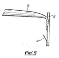
- the body In use the body can be bent away from the base as illustrated in Fig.5. The base can then be driven into the ground using a simple tool such as a hammer or mallet. When the body is released it springs back to the upright position. The whole operation takes a few minutes and requires no special equipment. The barb prevents the post from being pulled out of the ground.
- a hole may be preformed as by drilling. Provided that the hole has a diameter which is about the same as the maximum cross-sectional dimension of the base 12, insertion of the base into the hole can be accomplished quite readily and the base will be held firmly in the hole. Even if the hole is larger than the cross section of the base the barb will hold the post in place. The costs of this kind of installation do not greatly exceed the costs of installing the marker post of the invention in softer ground.
- the invention is not restricted to the above described embodiment. Many variations and modifications can be made.
- the post can carry some reflective material so that it will be noticeable at night when light falls onto it. Markings, whether reflective or not, can be applied to the post to give information, for example direction, distance, hazard warning, rights of way and the like.
- the post can be used to mark the line of footpaths, bridle paths or tracks and it can be used to mark the line of buried services such as gas, water, electricity and so on.
- body of the post being made of plastics
- other flexible materials can be used for example glass or carbon fibre reinforced plastics and materials made from carbon fibre.
Landscapes
- Engineering & Computer Science (AREA)
- Architecture (AREA)
- Civil Engineering (AREA)
- Structural Engineering (AREA)
- Road Signs Or Road Markings (AREA)
- Wrappers (AREA)
Applications Claiming Priority (2)
| Application Number | Priority Date | Filing Date | Title |
|---|---|---|---|
| GB8807036 | 1988-03-24 | ||
| GB888807036A GB8807036D0 (en) | 1988-03-24 | 1988-03-24 | Marker post |
Publications (1)
| Publication Number | Publication Date |
|---|---|
| EP0335591A1 true EP0335591A1 (de) | 1989-10-04 |
Family
ID=10634044
Family Applications (1)
| Application Number | Title | Priority Date | Filing Date |
|---|---|---|---|
| EP89302906A Withdrawn EP0335591A1 (de) | 1988-03-24 | 1989-03-23 | Leitpfosten |
Country Status (3)
| Country | Link |
|---|---|
| EP (1) | EP0335591A1 (de) |
| GB (1) | GB8807036D0 (de) |
| NO (1) | NO891284L (de) |
Cited By (2)
| Publication number | Priority date | Publication date | Assignee | Title |
|---|---|---|---|---|
| WO2004113619A1 (en) * | 2003-06-23 | 2004-12-29 | Delnorth Pty. Ltd. | Roadside post |
| AU2008100279B4 (en) * | 2003-06-23 | 2008-05-29 | Delnorth Pty. Ltd. | Roadside post |
Citations (5)
| Publication number | Priority date | Publication date | Assignee | Title |
|---|---|---|---|---|
| US2030623A (en) * | 1935-04-05 | 1936-02-11 | Oliver D Eggleston | Highway guard post |
| FR1311952A (fr) * | 1961-10-31 | 1962-12-14 | Vallette & Pavon Ets | Perfectionnements aux supports en forme de piquets pour panneaux de signalisation et analogues |
| LU82466A1 (fr) * | 1980-02-08 | 1980-10-08 | Tlb Plastics Corp | Poteau indicateur pour le balisage des routes |
| US4298292A (en) * | 1979-12-10 | 1981-11-03 | Franklin Steel Company | Traffic delineator |
| WO1983001972A1 (en) * | 1981-11-27 | 1983-06-09 | BJÖRLUND, John | A post, such as a roadside marking post, a traffic sign post or a lamp post |
-
1988
- 1988-03-24 GB GB888807036A patent/GB8807036D0/en active Pending
-
1989
- 1989-03-23 EP EP89302906A patent/EP0335591A1/de not_active Withdrawn
- 1989-03-28 NO NO89891284A patent/NO891284L/no unknown
Patent Citations (5)
| Publication number | Priority date | Publication date | Assignee | Title |
|---|---|---|---|---|
| US2030623A (en) * | 1935-04-05 | 1936-02-11 | Oliver D Eggleston | Highway guard post |
| FR1311952A (fr) * | 1961-10-31 | 1962-12-14 | Vallette & Pavon Ets | Perfectionnements aux supports en forme de piquets pour panneaux de signalisation et analogues |
| US4298292A (en) * | 1979-12-10 | 1981-11-03 | Franklin Steel Company | Traffic delineator |
| LU82466A1 (fr) * | 1980-02-08 | 1980-10-08 | Tlb Plastics Corp | Poteau indicateur pour le balisage des routes |
| WO1983001972A1 (en) * | 1981-11-27 | 1983-06-09 | BJÖRLUND, John | A post, such as a roadside marking post, a traffic sign post or a lamp post |
Non-Patent Citations (1)
| Title |
|---|
| HIGHWAYS, vol. 56, no. 1937, May 1988, page 29, Croydon, Surreay, GB; "Impact resistant marker postrange" * |
Cited By (3)
| Publication number | Priority date | Publication date | Assignee | Title |
|---|---|---|---|---|
| WO2004113619A1 (en) * | 2003-06-23 | 2004-12-29 | Delnorth Pty. Ltd. | Roadside post |
| AU2008100279B4 (en) * | 2003-06-23 | 2008-05-29 | Delnorth Pty. Ltd. | Roadside post |
| US7585127B2 (en) | 2003-06-23 | 2009-09-08 | Delnorth Pty. Ltd. | Roadside post |
Also Published As
| Publication number | Publication date |
|---|---|
| NO891284D0 (no) | 1989-03-28 |
| NO891284L (no) | 1989-09-25 |
| GB8807036D0 (en) | 1988-04-27 |
Similar Documents
| Publication | Publication Date | Title |
|---|---|---|
| US5848502A (en) | Removable post support system | |
| US4298292A (en) | Traffic delineator | |
| US4729690A (en) | Self-righting highway marker support and method for installing same | |
| US5484217A (en) | Restorable breakaway post | |
| US4240766A (en) | Traffic delineator | |
| EP0584109B1 (de) | Pfosteneinrichtung | |
| US5625988A (en) | Post support assembly having a mounting socket and a rigid collar | |
| US7451721B1 (en) | Utility location indicator apparatus | |
| US4594157A (en) | Inlet clamp and screen | |
| US20020073915A1 (en) | Ground marker | |
| US3335534A (en) | Highway replaceable post | |
| US20110293367A1 (en) | Roadway Marking Devices and Methods of Using Thereof | |
| US4908249A (en) | Markers for hydrants and other underground utilities fixtures | |
| US4435107A (en) | Traffic delineator | |
| EP0335591A1 (de) | Leitpfosten | |
| US4917531A (en) | Temporary device for use with a manhole support during street repairs | |
| US3860213A (en) | One-piece support | |
| US4353665A (en) | Delineator | |
| KR100483800B1 (ko) | 가드레일부착용 도로표지판 | |
| JPH0768687B2 (ja) | 標識支柱の補修方法 | |
| EP1636427B1 (de) | Strassenpfosten | |
| US20100143034A1 (en) | Method and Apparatus for a Roadway Marker | |
| GB2305948A (en) | Ground bolts | |
| KR20060027833A (ko) | 경계용 표주(標柱) | |
| US5295336A (en) | Releasable post anchoring device |
Legal Events
| Date | Code | Title | Description |
|---|---|---|---|
| PUAI | Public reference made under article 153(3) epc to a published international application that has entered the european phase |
Free format text: ORIGINAL CODE: 0009012 |
|
| AK | Designated contracting states |
Kind code of ref document: A1 Designated state(s): AT BE CH DE ES FR GB GR IT LI LU NL SE |
|
| 17P | Request for examination filed |
Effective date: 19900404 |
|
| 17Q | First examination report despatched |
Effective date: 19910311 |
|
| STAA | Information on the status of an ep patent application or granted ep patent |
Free format text: STATUS: THE APPLICATION IS DEEMED TO BE WITHDRAWN |
|
| 18D | Application deemed to be withdrawn |
Effective date: 19910924 |