EP0335475A2 - Centrifuge including improved thermoelectric temperature control assembly - Google Patents
Centrifuge including improved thermoelectric temperature control assembly Download PDFInfo
- Publication number
- EP0335475A2 EP0335475A2 EP89201159A EP89201159A EP0335475A2 EP 0335475 A2 EP0335475 A2 EP 0335475A2 EP 89201159 A EP89201159 A EP 89201159A EP 89201159 A EP89201159 A EP 89201159A EP 0335475 A2 EP0335475 A2 EP 0335475A2
- Authority
- EP
- European Patent Office
- Prior art keywords
- vessel
- thermoelectric
- heat sink
- devices
- substrate
- Prior art date
- Legal status (The legal status is an assumption and is not a legal conclusion. Google has not performed a legal analysis and makes no representation as to the accuracy of the status listed.)
- Granted
Links
Images

Classifications
-
- B—PERFORMING OPERATIONS; TRANSPORTING
- B04—CENTRIFUGAL APPARATUS OR MACHINES FOR CARRYING-OUT PHYSICAL OR CHEMICAL PROCESSES
- B04B—CENTRIFUGES
- B04B15/00—Other accessories for centrifuges
- B04B15/02—Other accessories for centrifuges for cooling, heating, or heat insulating
-
- F—MECHANICAL ENGINEERING; LIGHTING; HEATING; WEAPONS; BLASTING
- F25—REFRIGERATION OR COOLING; COMBINED HEATING AND REFRIGERATION SYSTEMS; HEAT PUMP SYSTEMS; MANUFACTURE OR STORAGE OF ICE; LIQUEFACTION SOLIDIFICATION OF GASES
- F25B—REFRIGERATION MACHINES, PLANTS OR SYSTEMS; COMBINED HEATING AND REFRIGERATION SYSTEMS; HEAT PUMP SYSTEMS
- F25B21/00—Machines, plants or systems, using electric or magnetic effects
- F25B21/02—Machines, plants or systems, using electric or magnetic effects using Peltier effect; using Nernst-Ettinghausen effect
Definitions
- the present invention relates to thermoelectric temperature control systems and is directed more particularly to an improved thermoelectric temperature control assembly which is specially adapted for use in Centrifuges.
- thermoelectric devices which utilize the Peltier effect have come into widespread use as solid-state heating and cooling elements.
- Thermoelectric devices have, for example, been widely used to control the temperatures of vessels and compartments, such as the refrigerated rotor compartments of centrifuges.
- thermoelectric devices do not exhibit the high thermal mass that characterizes temperature control systems which utilize liquid baths. This, in turn, allows the temperature that is established by the system to be changed at a rapid rate, thereby greatly increasing the rate at which batches of samples may be processed.
- Another reason for this widespread use is that the direction of heat flow through a thermoelectric device can be reversed by simply reversing the direction of current flow therethrough. As a result, temperature control systems which utilize thermoelectric devices need not utilize separate heating and cooling elements.
- thermoelectric heating and cooling systems One important consideration in the design of thermoelectric heating and cooling systems is the provision of structures whereby the heat which is removed or supplied by its thermoelectric devices may be conducted away from or toward the outer surfaces thereof.
- the outer surfaces of the thermoelectric devices are connected to a heat sink over which air is circulated.
- the outer surfaces of the thermoelectric devices are connected to jackets through which water is circulated.
- a system of the latter type which is used to cool a centrifuge is shown in U.S. Patent No. 3,347,453, which issued on October 17, 1967 in the name of K. Goergen.
- thermoelectric heating and cooling systems Another important consideration in the design of thermoelectric heating and cooling systems is the maintenance of a low thermal resistance between the inner and outer surfaces of the thermoelectric devices and the structures with which those surfaces are in contact
- This low thermal resistance may, for example, be established, in part, by grinding the contact surfaces flat and smooth and by applying thermally conductive grease therebetween.
- the desired low thermal resistance may also be established by using clamping arrangements to create a relatively high contact pressure between the thermoelectric devices and the structures with which they are in contact.
- thermoelectric devices Prior to the present invention, the clamping arrangements that have been used with thermoelectric devices have been relatively bulky and complex. Some clamping arrangements, for example, have required that each thermoelectric device be surrounded by a plurliaty of symmetrically positioned bolts which squeeze each device between the item to be cooled and a heat sink. Because each of these clamping bolts provides a thermal leakage path across the respective thermoelectric device, however, such arrangements have a poor efficienty.
- thermoelectric temperature control assembly which eliminates much of the cost and inconvenience that has been associated with the use of previously known thermoelectric heating and cooling systems. While the temperature control assembly of the invention is not limited to use in any particular application, it is particularly well suited for use in controlling the temperature of the rotor compartment of a centrifuge.
- the present invention contemplates the mounting of a plurality of thermoelectric devices in respective openings in a suitable electrically and thermally nonconducting substrate such as a printed circuit board.
- these openings are shaped in such a way that they define flexible tongues which serve as springs to clamp the edges of each thermoelectric device to one of the surfaces with which that device operates.
- the thermoelectric assembly of the invention does not require the use of separate clamps or of bolts that bridge the thermoelectric devices.
- the preferred embodiment of the invention also contemplates the use of the nonconducting substrate to support a plurality of bonding pads for the leads of the thermoelectric devices.
- these bonding pads can also be used to establish the desired electrical connections between the thermoelectric devices.
- thermoelectric assembly of the invention When the thermoelectric assembly of the invention is utilized with a centrifuge, it is preferably provided with a central hole through which the drive shaft of the centrifuge may pass.
- This central hole allows the thermoelectric assembly to be positioned beneath the vessel which encloses the rotor compartment.
- the latter location is particularly desirable because it allows the weight of the vessel to establish a good thermal contact with the thermoelectric devices. This, in turn, eliminates the need for clamping bolts between the vessel and the heat sink of the thermoelectric devices and thereby eliminates the above-mentioned heat leakage paths.
- This good thermal contact may be further improved by using spring loaded clamps to produce a downward force on the top of the vessel.
- Centrifuge 8 includes a drive motor 12 for driving a rotor 14, via a shaft 15 and hub (not shown), the internal detail of the motor and its associated drive components being omitted for the sake of clarity.
- rotor 14 is located within a temperature controlled compartment 16 that is enclosed by a generally cylindrical metal vessel 18 and by a cover (not shown).
- Vessel 18 is, in turn, enclosed by an explosion containment ring 20, an outer retaining wall 22 and upper and lower retaining walls 24 and 26, respectively.
- retaining walls 22, 24 and 26 may be used to form a sealed chamber within which a vacuum may be created if desired. Because the seals and pumps that are associated with the creation of a vacuum have no bearing on the present invention, they have been omitted for the sake of clarity.
- thermoelectric assembly 10 which has been constructed in accordance with the present invention.
- thermoelectric assembly 10 is positioned between the bottom of vessel 18 and a suitable heat sink 30.
- heat sink 30 comprises a circularly cut section of a conventional aluminum heat sink from which part or all of the central fins have been cut away in order to provide room for drive motor 12. This heat sink is supported on a circular shoulder in lower retaining wall 26.
- thermoelectric devices of assembly 10 are in direct, low thermal resistance contact with the upper surface of heat sink 30.
- the upper surfaces of the thermoelectric devices of assembly 10 are in direct, low thermal resistance contact with the bottom of vessel 18.
- thermoelectric devices can efficiently transfer heat either into or out of compartment 16, as necessary to maintain the desired temperature therein. This heat transfer is controlled by a conventional closed loop temperature control circuit (not shown) which directs current through the thermoelectric devices in response to the output of one or more thermistors that are located within bottom closure ring 17 of vessel 18.
- FIG. 1A there is shown an enlarged view of one of spring loaded assemblies 34.
- This assembly includes a pin 19, which is threaded into a suitable hole in upper retaining wall 24, a spring 20 and a generally cylindrical sleeve 21 having a clamping arm 21a.
- spring 21 is compressed between a snap ring 19a on pin 19 and the lower end of sleeve 21.
- arm 21a produces a downwardly clamping force on the edge of vessel 18.
- the strength of this clamping force may be adjusted by turning pin 19 via the slot that is provided in the upper end thereof.
- thermoelectric assembly 10 between vessel 18 and heat sink 30 tends to establish low thermal resistance contacts between the upper and lower surfaces of the thermoelectric devices and vessel 18 and heat sink 30.
- the thermal resistance at the lower surfaces of the thermoelectric devices is further improved by the clamping force which is produced by thermoelectric assembly 10 itself. The manner in which this clamping force is produced will now be described in connection with Figures 2A-2D.
- thermoelectric assembly 10 includes a nonconducting substrate 40 which preferably comprises a piece of printed circuit board. This substrate is provided with a central hole 42 to accommodate the drive shaft of rotor 14. Assembly 10 also includes a plurality of thermoelectric devices 50, 52 and 54, each of which may be of the type sold under the designation 801-3958-01 by the Cambion Division of Midland Oil Corporation. These devices are preferably spaced apart at equal angular intervals and are approximately equidistant from the center of ihe substrate. The latter relationships are desirable because they assure the establishment of a symmetrical heat flow pattern at the bottom of vessel and threby assure that vessel can be brought to the desired temperature in the shortest possible time. It will be understood, however, that the present invention is not limited either to any particular physical arrangement of thermoelectric devices or to any particular number of thermoelectric devices.
- substrate 40 is provided with a plurality of mounting openings or pockets 44 each of which has the shape shown in Figure 2C.
- the width of pocket 44 i.e., the distance between edges 44a and 44b thereof, is such that edges 44a and 44b can slide into respective slots in the sides of a respective thermoelectric device.
- the slots 54a and 54b in the sides of the thermoelectric device 54 which fits into pocket 44 are shown in Figure 2B.
- the thickness of substrate 40 need not be nearly closely matched to the width of the slots of the thermoelectric devices.
- pocket 44 is provided with secondary or stress relief openings 44c and 44d which, together with edges 44a and 44b of pocket 44 and adjacent edges 40a and 40b of substrate 40, define flexible tongues 48 which are used to clamp the respective thermoelectric device against heat sink 30.
- This clamping action results from the deformation of the tongues by clamping bolts 56 which pass through respective clamping holes 46 that are located within each tongue and engage the mating threads of respective holes in heat sink 30.
- This deformation of the tongues by the clamping bolts is shown in Figure 2D.
- the magnitude of the clamping force may be fixed at the desired value by inserting deformation limiting spacers such as 58 of Figure 2D between substrate 40 and heat sink 30.
- the magnitude of the clamping force may also be fixed at the desired value by selecting the proper distance between the clamping holes and the edges of the tongues.
- the location of the clamping holes within the tongues is such that the tongues produce an approximately uniform clamping pressure across the edges of the tongues.
- this location may or may not lie along the center line of the tongue. In the event that it is necessary to locate clamping holes 46 at their optimal off-center locations, those locations may be easily determined by experiment. In many cases, however, locating the clamping holes along the center lines of the tongues will provide an adequate degree of uniformity in the clamping force.
- secondary openings 44c and 44d have the shape shown in Figure 2C, they serve to define an additional tongue 49.
- This tongue serves as a convenient stop to fix the insertion depth of the thermoelectric devices in the respective pockets.
- tongue 49 may also be adapted for use as an additional clamping member by extending hole 44 to form additional openings 44e and 44f, shown in dotted lines in Figure 2C, and by providing tongue 49 with a suitably located clamping hole.
- substrate 40 is provided with a plurality of bonding pads for terminating and interconnecting the leads of the thermoelectric devices.
- these bonding pads comprise rectangular metallized regions 60 through 66 which are applied to substrate 40 in the same manner as the traces of printed circuit boards.
- Bonding pad 60 serves both to fasten leads 50a and 54b of thermoelectric devices 50 and 54 to substrate 40 and to produce a series connection therebetween.
- Bonding pads 64 serve a similar fastening function for leads 52a and 50b as well as providing convenient points at which the thermoelectric devices may be connected to the external source which supplies current thereto.
- the connection between the leads and the bonding pads also serves to hold the thermoelectric devices in place on substrate 40, thereby allowing assembly 10 to be handled and installed as a single unit.
- thermoelectric temperature control assembly of the present invention provides a number of advantages over previously used thermoelectric temperature control arrangements. Firstly, it allows a plurality of thermoelectric devices to be formed into a single unit which may be easily handled and installed. Secondly, it provides built-in clamping tongues whereby the individual thermoelectric devices may be clamped to an associated heat sink. Thirdly, it provides a convenient substrate which may be used to secure and interconnect all of the leads of the thermoelectric devices. Together these features represent a significant improvement in thermoelectric heating and cooling system technology.
Landscapes
- Engineering & Computer Science (AREA)
- Physics & Mathematics (AREA)
- Mechanical Engineering (AREA)
- Thermal Sciences (AREA)
- General Engineering & Computer Science (AREA)
- Centrifugal Separators (AREA)
Abstract
Description
- The present invention relates to thermoelectric temperature control systems and is directed more particularly to an improved thermoelectric temperature control assembly which is specially adapted for use in Centrifuges.
- Because of their small size and weight, thermoelectric devices which utilize the Peltier effect have come into widespread use as solid-state heating and cooling elements. Thermoelectric devices have, for example, been widely used to control the temperatures of vessels and compartments, such as the refrigerated rotor compartments of centrifuges. One reason for this widespread use is that thermoelectric devices do not exhibit the high thermal mass that characterizes temperature control systems which utilize liquid baths. This, in turn, allows the temperature that is established by the system to be changed at a rapid rate, thereby greatly increasing the rate at which batches of samples may be processed. Another reason for this widespread use is that the direction of heat flow through a thermoelectric device can be reversed by simply reversing the direction of current flow therethrough. As a result, temperature control systems which utilize thermoelectric devices need not utilize separate heating and cooling elements.
- One important consideration in the design of thermoelectric heating and cooling systems is the provision of structures whereby the heat which is removed or supplied by its thermoelectric devices may be conducted away from or toward the outer surfaces thereof. In some thermoelectric heating and cooling systems, for example, the outer surfaces of the thermoelectric devices are connected to a heat sink over which air is circulated. In other thermoelectric heating and cooling systems, the outer surfaces of the thermoelectric devices are connected to jackets through which water is circulated. A system of the latter type which is used to cool a centrifuge is shown in U.S. Patent No. 3,347,453, which issued on October 17, 1967 in the name of K. Goergen.
- Another important consideration in the design of thermoelectric heating and cooling systems is the maintenance of a low thermal resistance between the inner and outer surfaces of the thermoelectric devices and the structures with which those surfaces are in contact This low thermal resistance may, for example, be established, in part, by grinding the contact surfaces flat and smooth and by applying thermally conductive grease therebetween. The desired low thermal resistance may also be established by using clamping arrangements to create a relatively high contact pressure between the thermoelectric devices and the structures with which they are in contact.
- Prior to the present invention, the clamping arrangements that have been used with thermoelectric devices have been relatively bulky and complex. Some clamping arrangements, for example, have required that each thermoelectric device be surrounded by a plurliaty of symmetrically positioned bolts which squeeze each device between the item to be cooled and a heat sink. Because each of these clamping bolts provides a thermal leakage path across the respective thermoelectric device, however, such arrangements have a poor efficienty.
- Other clamping arrangements have required the use of a plurality of bolt-tightened clamps for clamping each edge of each thermoelectric device to the desired contact surface. When several thermoelectric devices are used with a clamping arrangement of this type, however, much time and effort is consumed in properly positioning and tightening the many separate pieces. The cost of assembling a thermoelectric heating and cooling system of this type is further increased by the fact that provision must be made for routing and securing the leads of each thermoelectric device. Thus, clamping arrangements of this type are costly and time consuming to install.
- In accordance with the present invention, there is provided an improved thermoelectric temperature control assembly which eliminates much of the cost and inconvenience that has been associated with the use of previously known thermoelectric heating and cooling systems. While the temperature control assembly of the invention is not limited to use in any particular application, it is particularly well suited for use in controlling the temperature of the rotor compartment of a centrifuge.
- Generally speaking, the present invention contemplates the mounting of a plurality of thermoelectric devices in respective openings in a suitable electrically and thermally nonconducting substrate such as a printed circuit board. In the preferred embodiment these openings are shaped in such a way that they define flexible tongues which serve as springs to clamp the edges of each thermoelectric device to one of the surfaces with which that device operates. As a result, the thermoelectric assembly of the invention does not require the use of separate clamps or of bolts that bridge the thermoelectric devices.
- The preferred embodiment of the invention also contemplates the use of the nonconducting substrate to support a plurality of bonding pads for the leads of the thermoelectric devices. When the leads of these devices are to be connected in series and/or in parallel, these bonding pads can also be used to establish the desired electrical connections between the thermoelectric devices. As a result, the problem of supplying power to each of a plurality of thermoelectric devices is reduced to the problem of connecting an external power supply to a single pair of bonding pads. The assembly of the invention thereby simplifies and reduces the cost of electrically connecting a plurality of thermoelectric devices.
- When the thermoelectric assembly of the invention is utilized with a centrifuge, it is preferably provided with a central hole through which the drive shaft of the centrifuge may pass. This central hole allows the thermoelectric assembly to be positioned beneath the vessel which encloses the rotor compartment. The latter location is particularly desirable because it allows the weight of the vessel to establish a good thermal contact with the thermoelectric devices. This, in turn, eliminates the need for clamping bolts between the vessel and the heat sink of the thermoelectric devices and thereby eliminates the above-mentioned heat leakage paths. This good thermal contact may be further improved by using spring loaded clamps to produce a downward force on the top of the vessel.
- Other objects and advantages of the present invention will be apparent from the following description and drawings, in which:
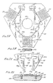
- Figure 1 is a simplified cross-sectional view of a centrifuge which is equipped with the thermoelectric temperature control assembly of the present invention;
- Figure 2A is a plan view of the thermoelectric temperature control assembly of Figure 1;
- Figure 2B is a front view of one of the thermoelectric devices of Figure 2A;
- Figure 2C is a plan view of a part of the assembly of Figure 2A, shown with the thermoelectrlc device removed; and
- Figure 2D is a partial cut away view showing the assembly of the invention mounted on a heat sink.
- Referring to Figure 1, there is shown a simplified cross-sectional view of a centrifuge 8 which, except in respects which will be discussed more fully later, is of a generally conventional design. Centrifuge 8 includes a
drive motor 12 for driving a rotor 14, via ashaft 15 and hub (not shown), the internal detail of the motor and its associated drive components being omitted for the sake of clarity. - In the embodiment of Figure 1, rotor 14 is located within a temperature controlled compartment 16 that is enclosed by a generally
cylindrical metal vessel 18 and by a cover (not shown).Vessel 18 is, in turn, enclosed by anexplosion containment ring 20, an outerretaining wall 22 and upper and lowerretaining walls 24 and 26, respectively. Together with a cover (not shown), retainingwalls - To the end that heat may be removed from or supplied to
vessel 18 in order to maintain the desired temperature within compartment 16, the centrifuge of Figure 1 includes a thermoelectrictemperature control assembly 10 which has been constructed in accordance with the present invention. In the embodiment of Figure 1,thermoelectric assembly 10 is positioned between the bottom ofvessel 18 and asuitable heat sink 30. Preferably,heat sink 30 comprises a circularly cut section of a conventional aluminum heat sink from which part or all of the central fins have been cut away in order to provide room fordrive motor 12. This heat sink is supported on a circular shoulder in lower retaining wall 26. - As will be explained more fully in connection with Figure 2, the lower surfaces of the thermoelectric devices of
assembly 10 are in direct, low thermal resistance contact with the upper surface ofheat sink 30. In addition, the upper surfaces of the thermoelectric devices ofassembly 10 are in direct, low thermal resistance contact with the bottom ofvessel 18. As a result, these thermoelectric devices can efficiently transfer heat either into or out of compartment 16, as necessary to maintain the desired temperature therein. This heat transfer is controlled by a conventional closed loop temperature control circuit (not shown) which directs current through the thermoelectric devices in response to the output of one or more thermistors that are located withinbottom closure ring 17 ofvessel 18. - Because
vessel 18 rests directly on the thermoelectric devices ofassembly 10, its weight helps to maintain the high contact pressure which is necessary to establish a good thermal contact between itself and the thermoelectric devices. In the event that additional pressure is necessary, it may be provided by including a plurality of spring loadedclamp assemblies 34 which tend to pushvessel 18 downwardly againstassembly 10. In the embodiment of Figure 1 four of these spring loaded clamp assemblies are mounted on upperretaining wall 24, where they hang downwardly and engage the upper rim ofvessel 18. This engagement with the top ofvessel 18 is highly advantageous because it allowsvessel 18 to pushed against the thermoelectric devices without creating a thermal leakage path betweenvessel 18 andheat sink 30. It will be understood, however, that other clamping assemblies and clamping locations may be used to produce the leakage free contact which is contemplated by the present invention. - Referring to Figure 1A, there is shown an enlarged view of one of spring loaded
assemblies 34. This assembly includes apin 19, which is threaded into a suitable hole in upperretaining wall 24, aspring 20 and a generallycylindrical sleeve 21 having a clamping arm 21a. In use,spring 21 is compressed between a snap ring 19a onpin 19 and the lower end ofsleeve 21. As a result of this compression, arm 21a produces a downwardly clamping force on the edge ofvessel 18. The strength of this clamping force may be adjusted by turningpin 19 via the slot that is provided in the upper end thereof. - In view of the foregoing it will be seen that locating
thermoelectric assembly 10 betweenvessel 18 andheat sink 30 tends to establish low thermal resistance contacts between the upper and lower surfaces of the thermoelectric devices andvessel 18 andheat sink 30. The thermal resistance at the lower surfaces of the thermoelectric devices is further improved by the clamping force which is produced bythermoelectric assembly 10 itself. The manner in which this clamping force is produced will now be described in connection with Figures 2A-2D. - As shown in Figure 2A,
thermoelectric assembly 10 includes anonconducting substrate 40 which preferably comprises a piece of printed circuit board. This substrate is provided with acentral hole 42 to accommodate the drive shaft of rotor 14.Assembly 10 also includes a plurality ofthermoelectric devices - In order to hold thermoelectric devices 50-54 in the desired positions thereon,
substrate 40 is provided with a plurality of mounting openings orpockets 44 each of which has the shape shown in Figure 2C. In the preferred embodiment, the width ofpocket 44, i.e., the distance betweenedges edges slots thermoelectric device 54 which fits intopocket 44 are shown in Figure 2B. For reasons which become clear later, the thickness ofsubstrate 40 need not be nearly closely matched to the width of the slots of the thermoelectric devices. - In accordance with one important feature of the present invention,
pocket 44 is provided with secondary or stress relief openings 44c and 44d which, together withedges pocket 44 and adjacent edges 40a and 40b ofsubstrate 40, defineflexible tongues 48 which are used to clamp the respective thermoelectric device againstheat sink 30. This clamping action results from the deformation of the tongues by clampingbolts 56 which pass through respective clamping holes 46 that are located within each tongue and engage the mating threads of respective holes inheat sink 30. This deformation of the tongues by the clamping bolts is shown in Figure 2D. Advantageously, the magnitude of the clamping force may be fixed at the desired value by inserting deformation limiting spacers such as 58 of Figure 2D betweensubstrate 40 andheat sink 30. The magnitude of the clamping force may also be fixed at the desired value by selecting the proper distance between the clamping holes and the edges of the tongues. - In the preferred embodiment, the location of the clamping holes within the tongues is such that the tongues produce an approximately uniform clamping pressure across the edges of the tongues. Depending on the shape of secondary openings 44c and 44d, and the shape of edges 40a and 40b, this location may or may not lie along the center line of the tongue. In the event that it is necessary to locate clamping
holes 46 at their optimal off-center locations, those locations may be easily determined by experiment. In many cases, however, locating the clamping holes along the center lines of the tongues will provide an adequate degree of uniformity in the clamping force. - If secondary openings 44c and 44d have the shape shown in Figure 2C, they serve to define an
additional tongue 49. This tongue serves as a convenient stop to fix the insertion depth of the thermoelectric devices in the respective pockets. If desired,tongue 49 may also be adapted for use as an additional clamping member by extendinghole 44 to formadditional openings 44e and 44f, shown in dotted lines in Figure 2C, and by providingtongue 49 with a suitably located clamping hole. - In accordance with another important feature of the present invention,
substrate 40 is provided with a plurality of bonding pads for terminating and interconnecting the leads of the thermoelectric devices. In Figure 2A, these bonding pads comprise rectangular metallizedregions 60 through 66 which are applied tosubstrate 40 in the same manner as the traces of printed circuit boards.Bonding pad 60, for example, serves both to fastenleads 50a and 54b ofthermoelectric devices 50 and 54 tosubstrate 40 and to produce a series connection therebetween.Bonding pads 64 serve a similar fastening function forleads 52a and 50b as well as providing convenient points at which the thermoelectric devices may be connected to the external source which supplies current thereto. The connection between the leads and the bonding pads also serves to hold the thermoelectric devices in place onsubstrate 40, thereby allowingassembly 10 to be handled and installed as a single unit. - In view of the foregoing, it will be seen that the thermoelectric temperature control assembly of the present invention provides a number of advantages over previously used thermoelectric temperature control arrangements. Firstly, it allows a plurality of thermoelectric devices to be formed into a single unit which may be easily handled and installed. Secondly, it provides built-in clamping tongues whereby the individual thermoelectric devices may be clamped to an associated heat sink. Thirdly, it provides a convenient substrate which may be used to secure and interconnect all of the leads of the thermoelectric devices. Together these features represent a significant improvement in thermoelectric heating and cooling system technology.
Claims (7)
(i) a nonconducting substrate (40), and
(ii) at least one thermoelectric device (50, 52, 54) attached to the substrate,
(c) said assembly being positioned between the vessel (18) and the heat sink (30) so that the upper surface of the thermoelectric device (50, 52, 54) is in direct thermal contact with the vessel (18) and the lower surface of the thermoelectric device (50, 52, 54) is in direct thermal contact with the heat sink (30),
(d) whereby the weight of the vessel (18) lessens the thermal resistance of said thermal contacts.
Priority Applications (1)
| Application Number | Priority Date | Filing Date | Title |
|---|---|---|---|
| AT8989201159T ATE105213T1 (en) | 1984-04-30 | 1985-03-18 | CENTRIFUGE WITH THERMOELECTRIC TEMPERATURE CONTROL UNIT. |
Applications Claiming Priority (3)
| Application Number | Priority Date | Filing Date | Title |
|---|---|---|---|
| US605360 | 1984-04-30 | ||
| US06/605,360 US4512758A (en) | 1984-04-30 | 1984-04-30 | Thermoelectric temperature control assembly for centrifuges |
| EP85901768A EP0185672B1 (en) | 1984-04-30 | 1985-03-18 | Thermoelectric temperature control assembly |
Related Parent Applications (3)
| Application Number | Title | Priority Date | Filing Date |
|---|---|---|---|
| EP85901768A Division-Into EP0185672B1 (en) | 1984-04-30 | 1985-03-18 | Thermoelectric temperature control assembly |
| EP85901768A Division EP0185672B1 (en) | 1984-04-30 | 1985-03-18 | Thermoelectric temperature control assembly |
| EP85901768.3 Division | 1985-11-26 |
Publications (3)
| Publication Number | Publication Date |
|---|---|
| EP0335475A2 true EP0335475A2 (en) | 1989-10-04 |
| EP0335475A3 EP0335475A3 (en) | 1991-01-02 |
| EP0335475B1 EP0335475B1 (en) | 1994-05-04 |
Family
ID=26101226
Family Applications (1)
| Application Number | Title | Priority Date | Filing Date |
|---|---|---|---|
| EP89201159A Expired - Lifetime EP0335475B1 (en) | 1984-04-30 | 1985-03-18 | Centrifuge including improved thermoelectric temperature control assembly |
Country Status (1)
| Country | Link |
|---|---|
| EP (1) | EP0335475B1 (en) |
Cited By (4)
| Publication number | Priority date | Publication date | Assignee | Title |
|---|---|---|---|---|
| DE4341333B4 (en) * | 1993-12-03 | 2004-04-29 | Deltron Elektronische Systeme Gmbh | Method for operating an electronic immobilizer and electronic immobilizer for motor vehicles |
| US20170189916A1 (en) * | 2014-05-23 | 2017-07-06 | Andreas Hettich Gmbh & Co. Kg | Centrifuge |
| CN113083517A (en) * | 2021-03-31 | 2021-07-09 | 江苏南大生态环境建设有限公司 | Waste emulsion treatment device |
| AT525851A3 (en) * | 2022-01-27 | 2023-08-15 | Henning Lange Asschenfeldt Prof Dr | Method and device for thermoelectric conversion by mediation of centrifugal force |
Families Citing this family (1)
| Publication number | Priority date | Publication date | Assignee | Title |
|---|---|---|---|---|
| US9018511B2 (en) | 2013-03-08 | 2015-04-28 | Hamilton Sundstrand Space Systems International, Inc. | Spring-loaded heat exchanger fins |
Citations (9)
| Publication number | Priority date | Publication date | Assignee | Title |
|---|---|---|---|---|
| US3232063A (en) * | 1964-06-26 | 1966-02-01 | Whirlpool Co | Cooling plate and shelf structure |
| US3326727A (en) * | 1962-07-11 | 1967-06-20 | Minnesota Mining & Mfg | Thermopile module with displacement permitting slotted thermojunction members |
| US3347453A (en) * | 1962-05-12 | 1967-10-17 | Martin Christ Fa | Centrifuges having rotor rotating in a vacuum |
| US3409212A (en) * | 1966-07-14 | 1968-11-05 | Beckman Instrumetns Inc | Apparatus for controllling centrifuge rotor temperature |
| US3412566A (en) * | 1965-06-21 | 1968-11-26 | Borg Warner | Thermoelectric apparatus |
| US3444695A (en) * | 1967-03-20 | 1969-05-20 | Int Equipment Co | Refrigerated centrifuge |
| US3447695A (en) * | 1966-11-21 | 1969-06-03 | P & F Ind Inc | Stacker |
| US3554815A (en) * | 1963-04-30 | 1971-01-12 | Du Pont | Thin,flexible thermoelectric device |
| US3804324A (en) * | 1972-06-27 | 1974-04-16 | Heraeus Christ Gmbh | Table top, noise suppressed centrifuge |
-
1985
- 1985-03-18 EP EP89201159A patent/EP0335475B1/en not_active Expired - Lifetime
Patent Citations (9)
| Publication number | Priority date | Publication date | Assignee | Title |
|---|---|---|---|---|
| US3347453A (en) * | 1962-05-12 | 1967-10-17 | Martin Christ Fa | Centrifuges having rotor rotating in a vacuum |
| US3326727A (en) * | 1962-07-11 | 1967-06-20 | Minnesota Mining & Mfg | Thermopile module with displacement permitting slotted thermojunction members |
| US3554815A (en) * | 1963-04-30 | 1971-01-12 | Du Pont | Thin,flexible thermoelectric device |
| US3232063A (en) * | 1964-06-26 | 1966-02-01 | Whirlpool Co | Cooling plate and shelf structure |
| US3412566A (en) * | 1965-06-21 | 1968-11-26 | Borg Warner | Thermoelectric apparatus |
| US3409212A (en) * | 1966-07-14 | 1968-11-05 | Beckman Instrumetns Inc | Apparatus for controllling centrifuge rotor temperature |
| US3447695A (en) * | 1966-11-21 | 1969-06-03 | P & F Ind Inc | Stacker |
| US3444695A (en) * | 1967-03-20 | 1969-05-20 | Int Equipment Co | Refrigerated centrifuge |
| US3804324A (en) * | 1972-06-27 | 1974-04-16 | Heraeus Christ Gmbh | Table top, noise suppressed centrifuge |
Cited By (7)
| Publication number | Priority date | Publication date | Assignee | Title |
|---|---|---|---|---|
| DE4341333B4 (en) * | 1993-12-03 | 2004-04-29 | Deltron Elektronische Systeme Gmbh | Method for operating an electronic immobilizer and electronic immobilizer for motor vehicles |
| US20170189916A1 (en) * | 2014-05-23 | 2017-07-06 | Andreas Hettich Gmbh & Co. Kg | Centrifuge |
| US10894260B2 (en) * | 2014-05-23 | 2021-01-19 | Andreas Hettich Gmbh & Co. Kg | Centrifuge refrigeration via magnetocaloric system |
| CN113083517A (en) * | 2021-03-31 | 2021-07-09 | 江苏南大生态环境建设有限公司 | Waste emulsion treatment device |
| AT525851A3 (en) * | 2022-01-27 | 2023-08-15 | Henning Lange Asschenfeldt Prof Dr | Method and device for thermoelectric conversion by mediation of centrifugal force |
| AT525851A2 (en) * | 2022-01-27 | 2023-08-15 | Henning Lange Asschenfeldt Prof Dr | Method and device for thermoelectric conversion by mediation of centrifugal force |
| AT525851B1 (en) * | 2022-01-27 | 2024-03-15 | Henning Lange Asschenfeldt Prof Dr | Method and device for thermoelectric conversion by mediating centrifugal force |
Also Published As
| Publication number | Publication date |
|---|---|
| EP0335475B1 (en) | 1994-05-04 |
| EP0335475A3 (en) | 1991-01-02 |
Similar Documents
| Publication | Publication Date | Title |
|---|---|---|
| US4512758A (en) | Thermoelectric temperature control assembly for centrifuges | |
| US5258887A (en) | Electrical device cooling system using a heat sink attached to a circuit board containing heat conductive layers and channels | |
| US5109317A (en) | Mounting mechanism for mounting heat sink on multi-chip module | |
| US4246597A (en) | Air cooled multi-chip module having a heat conductive piston spring loaded against the chips | |
| US4887147A (en) | Thermal package for electronic components | |
| US4253515A (en) | Integrated circuit temperature gradient and moisture regulator | |
| US4468717A (en) | Apparatus for cooling integrated circuit chips | |
| EP0302641B1 (en) | Cooling structure for heat generating electronic components mounted on a substrate | |
| US5077638A (en) | Heat sink for an electric circuit board | |
| US5088005A (en) | Cold plate for cooling electronics | |
| US7120024B2 (en) | Electronic control device | |
| US6054676A (en) | Method and apparatus for cooling an integrated circuit device | |
| US5270902A (en) | Heat transfer device for use with a heat sink in removing thermal energy from an integrated circuit chip | |
| EP0622983B1 (en) | Electronic component heat sink attachment using a low force spring | |
| US5883426A (en) | Stack module | |
| US5920457A (en) | Apparatus for cooling electronic devices using a flexible coolant conduit | |
| EP0618618A1 (en) | Apparatus for containing and cooling an integrated circuit device | |
| US20060133039A1 (en) | Fluid cooled integrated circuit module | |
| KR860007733A (en) | Integrated circuit chip chiller | |
| EP0625871A1 (en) | Electronic component heat sink attachment using a canted coil spring | |
| NO168150B (en) | ELECTRONIC MODULE WITH SELF-DRIVED COOLING DEVICE | |
| SE521666C2 (en) | Mounting structure for a power transistor module with a radiation kiode | |
| JPH03236578A (en) | Thermoelectric device for heating or cooling food and drink container | |
| US4115836A (en) | Cooling system for dual-in-line packages | |
| JP3069800B2 (en) | Assembly for controlling refrigerant flow rate and method of installing thermistor |
Legal Events
| Date | Code | Title | Description |
|---|---|---|---|
| PUAI | Public reference made under article 153(3) epc to a published international application that has entered the european phase |
Free format text: ORIGINAL CODE: 0009012 |
|
| 17P | Request for examination filed |
Effective date: 19890531 |
|
| AC | Divisional application: reference to earlier application |
Ref document number: 185672 Country of ref document: EP |
|
| AK | Designated contracting states |
Kind code of ref document: A2 Designated state(s): AT BE CH DE FR GB LI LU NL SE |
|
| RIN1 | Information on inventor provided before grant (corrected) |
Inventor name: GIEBELER, ROBERT HENRY, JR. Inventor name: WEDEMEYER, ROBERT CARL |
|
| PUAL | Search report despatched |
Free format text: ORIGINAL CODE: 0009013 |
|
| AK | Designated contracting states |
Kind code of ref document: A3 Designated state(s): AT BE CH DE FR GB LI LU NL SE |
|
| 17Q | First examination report despatched |
Effective date: 19920206 |
|
| GRAA | (expected) grant |
Free format text: ORIGINAL CODE: 0009210 |
|
| AC | Divisional application: reference to earlier application |
Ref document number: 185672 Country of ref document: EP |
|
| AK | Designated contracting states |
Kind code of ref document: B1 Designated state(s): AT BE CH DE FR GB LI LU NL SE |
|
| PG25 | Lapsed in a contracting state [announced via postgrant information from national office to epo] |
Ref country code: SE Free format text: THE PATENT HAS BEEN ANNULLED BY A DECISION OF A NATIONAL AUTHORITY Effective date: 19940504 Ref country code: NL Effective date: 19940504 Ref country code: LI Effective date: 19940504 Ref country code: CH Effective date: 19940504 Ref country code: BE Effective date: 19940504 Ref country code: AT Effective date: 19940504 |
|
| REF | Corresponds to: |
Ref document number: 105213 Country of ref document: AT Date of ref document: 19940515 Kind code of ref document: T |
|
| REF | Corresponds to: |
Ref document number: 3587815 Country of ref document: DE Date of ref document: 19940609 |
|
| REG | Reference to a national code |
Ref country code: CH Ref legal event code: PL |
|
| ET | Fr: translation filed | ||
| NLV1 | Nl: lapsed or annulled due to failure to fulfill the requirements of art. 29p and 29m of the patents act | ||
| PLBE | No opposition filed within time limit |
Free format text: ORIGINAL CODE: 0009261 |
|
| STAA | Information on the status of an ep patent application or granted ep patent |
Free format text: STATUS: NO OPPOSITION FILED WITHIN TIME LIMIT |
|
| PG25 | Lapsed in a contracting state [announced via postgrant information from national office to epo] |
Ref country code: LU Free format text: LAPSE BECAUSE OF NON-PAYMENT OF DUE FEES Effective date: 19950331 |
|
| 26N | No opposition filed | ||
| PGFP | Annual fee paid to national office [announced via postgrant information from national office to epo] |
Ref country code: GB Payment date: 19970205 Year of fee payment: 13 |
|
| PGFP | Annual fee paid to national office [announced via postgrant information from national office to epo] |
Ref country code: FR Payment date: 19970307 Year of fee payment: 13 |
|
| PGFP | Annual fee paid to national office [announced via postgrant information from national office to epo] |
Ref country code: DE Payment date: 19970326 Year of fee payment: 13 |
|
| PG25 | Lapsed in a contracting state [announced via postgrant information from national office to epo] |
Ref country code: GB Free format text: LAPSE BECAUSE OF NON-PAYMENT OF DUE FEES Effective date: 19980318 |
|
| PG25 | Lapsed in a contracting state [announced via postgrant information from national office to epo] |
Ref country code: FR Free format text: THE PATENT HAS BEEN ANNULLED BY A DECISION OF A NATIONAL AUTHORITY Effective date: 19980331 |
|
| GBPC | Gb: european patent ceased through non-payment of renewal fee |
Effective date: 19980318 |
|
| PG25 | Lapsed in a contracting state [announced via postgrant information from national office to epo] |
Ref country code: DE Free format text: LAPSE BECAUSE OF NON-PAYMENT OF DUE FEES Effective date: 19981201 |
|
| REG | Reference to a national code |
Ref country code: FR Ref legal event code: ST |