EP0335321B1 - Adaptive architectural cover panel system - Google Patents
Adaptive architectural cover panel system Download PDFInfo
- Publication number
- EP0335321B1 EP0335321B1 EP19890105435 EP89105435A EP0335321B1 EP 0335321 B1 EP0335321 B1 EP 0335321B1 EP 19890105435 EP19890105435 EP 19890105435 EP 89105435 A EP89105435 A EP 89105435A EP 0335321 B1 EP0335321 B1 EP 0335321B1
- Authority
- EP
- European Patent Office
- Prior art keywords
- support members
- corrugations
- cover panels
- panels
- architectural
- Prior art date
- Legal status (The legal status is an assumption and is not a legal conclusion. Google has not performed a legal analysis and makes no representation as to the accuracy of the status listed.)
- Expired
Links
- 230000003044 adaptive effect Effects 0.000 title description 12
- 239000000463 material Substances 0.000 claims description 9
- 238000000034 method Methods 0.000 claims description 6
- 238000005728 strengthening Methods 0.000 claims 2
- 230000008602 contraction Effects 0.000 description 4
- 239000002184 metal Substances 0.000 description 2
- 229910052751 metal Inorganic materials 0.000 description 2
- 229920003023 plastic Polymers 0.000 description 2
- 239000004033 plastic Substances 0.000 description 2
- 230000002787 reinforcement Effects 0.000 description 2
- 238000009966 trimming Methods 0.000 description 2
- 239000002131 composite material Substances 0.000 description 1
- 238000010276 construction Methods 0.000 description 1
- 150000002739 metals Chemical class 0.000 description 1
- 238000012986 modification Methods 0.000 description 1
- 230000004048 modification Effects 0.000 description 1
Images
Classifications
-
- E—FIXED CONSTRUCTIONS
- E01—CONSTRUCTION OF ROADS, RAILWAYS, OR BRIDGES
- E01D—CONSTRUCTION OF BRIDGES, ELEVATED ROADWAYS OR VIADUCTS; ASSEMBLY OF BRIDGES
- E01D19/00—Structural or constructional details of bridges
- E01D19/10—Railings; Protectors against smoke or gases, e.g. of locomotives; Maintenance travellers; Fastening of pipes or cables to bridges
-
- E—FIXED CONSTRUCTIONS
- E01—CONSTRUCTION OF ROADS, RAILWAYS, OR BRIDGES
- E01F—ADDITIONAL WORK, SUCH AS EQUIPPING ROADS OR THE CONSTRUCTION OF PLATFORMS, HELICOPTER LANDING STAGES, SIGNS, SNOW FENCES, OR THE LIKE
- E01F8/00—Arrangements for absorbing or reflecting air-transmitted noise from road or railway traffic
- E01F8/0005—Arrangements for absorbing or reflecting air-transmitted noise from road or railway traffic used in a wall type arrangement
- E01F8/0023—Details, e.g. foundations
-
- E—FIXED CONSTRUCTIONS
- E01—CONSTRUCTION OF ROADS, RAILWAYS, OR BRIDGES
- E01F—ADDITIONAL WORK, SUCH AS EQUIPPING ROADS OR THE CONSTRUCTION OF PLATFORMS, HELICOPTER LANDING STAGES, SIGNS, SNOW FENCES, OR THE LIKE
- E01F8/00—Arrangements for absorbing or reflecting air-transmitted noise from road or railway traffic
- E01F8/0005—Arrangements for absorbing or reflecting air-transmitted noise from road or railway traffic used in a wall type arrangement
- E01F8/0047—Arrangements for absorbing or reflecting air-transmitted noise from road or railway traffic used in a wall type arrangement with open cavities, e.g. for covering sunken roads
- E01F8/0064—Perforated plate or mesh, e.g. as wall facing
- E01F8/007—Perforated plate or mesh, e.g. as wall facing with damping material
-
- E—FIXED CONSTRUCTIONS
- E04—BUILDING
- E04B—GENERAL BUILDING CONSTRUCTIONS; WALLS, e.g. PARTITIONS; ROOFS; FLOORS; CEILINGS; INSULATION OR OTHER PROTECTION OF BUILDINGS
- E04B1/00—Constructions in general; Structures which are not restricted either to walls, e.g. partitions, or floors or ceilings or roofs
- E04B1/62—Insulation or other protection; Elements or use of specified material therefor
- E04B1/74—Heat, sound or noise insulation, absorption, or reflection; Other building methods affording favourable thermal or acoustical conditions, e.g. accumulating of heat within walls
- E04B1/82—Heat, sound or noise insulation, absorption, or reflection; Other building methods affording favourable thermal or acoustical conditions, e.g. accumulating of heat within walls specifically with respect to sound only
- E04B1/84—Sound-absorbing elements
- E04B1/86—Sound-absorbing elements slab-shaped
-
- E—FIXED CONSTRUCTIONS
- E04—BUILDING
- E04B—GENERAL BUILDING CONSTRUCTIONS; WALLS, e.g. PARTITIONS; ROOFS; FLOORS; CEILINGS; INSULATION OR OTHER PROTECTION OF BUILDINGS
- E04B7/00—Roofs; Roof construction with regard to insulation
- E04B7/08—Vaulted roofs
- E04B7/10—Shell structures, e.g. of hyperbolic-parabolic shape; Grid-like formations acting as shell structures; Folded structures
- E04B7/107—Folded structures
-
- E—FIXED CONSTRUCTIONS
- E04—BUILDING
- E04B—GENERAL BUILDING CONSTRUCTIONS; WALLS, e.g. PARTITIONS; ROOFS; FLOORS; CEILINGS; INSULATION OR OTHER PROTECTION OF BUILDINGS
- E04B9/00—Ceilings; Construction of ceilings, e.g. false ceilings; Ceiling construction with regard to insulation
- E04B9/02—Ceilings; Construction of ceilings, e.g. false ceilings; Ceiling construction with regard to insulation having means for ventilation or vapour discharge
-
- E—FIXED CONSTRUCTIONS
- E04—BUILDING
- E04B—GENERAL BUILDING CONSTRUCTIONS; WALLS, e.g. PARTITIONS; ROOFS; FLOORS; CEILINGS; INSULATION OR OTHER PROTECTION OF BUILDINGS
- E04B9/00—Ceilings; Construction of ceilings, e.g. false ceilings; Ceiling construction with regard to insulation
- E04B9/34—Grid-like or open-work ceilings, e.g. lattice type box-like modules, acoustic baffles
-
- E—FIXED CONSTRUCTIONS
- E04—BUILDING
- E04C—STRUCTURAL ELEMENTS; BUILDING MATERIALS
- E04C2/00—Building elements of relatively thin form for the construction of parts of buildings, e.g. sheet materials, slabs, or panels
- E04C2/30—Building elements of relatively thin form for the construction of parts of buildings, e.g. sheet materials, slabs, or panels characterised by the shape or structure
- E04C2/32—Building elements of relatively thin form for the construction of parts of buildings, e.g. sheet materials, slabs, or panels characterised by the shape or structure formed of corrugated or otherwise indented sheet-like material; composed of such layers with or without layers of flat sheet-like material
- E04C2/322—Building elements of relatively thin form for the construction of parts of buildings, e.g. sheet materials, slabs, or panels characterised by the shape or structure formed of corrugated or otherwise indented sheet-like material; composed of such layers with or without layers of flat sheet-like material with parallel corrugations
-
- E—FIXED CONSTRUCTIONS
- E04—BUILDING
- E04C—STRUCTURAL ELEMENTS; BUILDING MATERIALS
- E04C2/00—Building elements of relatively thin form for the construction of parts of buildings, e.g. sheet materials, slabs, or panels
- E04C2/30—Building elements of relatively thin form for the construction of parts of buildings, e.g. sheet materials, slabs, or panels characterised by the shape or structure
- E04C2/32—Building elements of relatively thin form for the construction of parts of buildings, e.g. sheet materials, slabs, or panels characterised by the shape or structure formed of corrugated or otherwise indented sheet-like material; composed of such layers with or without layers of flat sheet-like material
- E04C2/326—Building elements of relatively thin form for the construction of parts of buildings, e.g. sheet materials, slabs, or panels characterised by the shape or structure formed of corrugated or otherwise indented sheet-like material; composed of such layers with or without layers of flat sheet-like material with corrugations, incisions or reliefs in more than one direction of the element
-
- E—FIXED CONSTRUCTIONS
- E04—BUILDING
- E04F—FINISHING WORK ON BUILDINGS, e.g. STAIRS, FLOORS
- E04F13/00—Coverings or linings, e.g. for walls or ceilings
- E04F13/07—Coverings or linings, e.g. for walls or ceilings composed of covering or lining elements; Sub-structures therefor; Fastening means therefor
- E04F13/08—Coverings or linings, e.g. for walls or ceilings composed of covering or lining elements; Sub-structures therefor; Fastening means therefor composed of a plurality of similar covering or lining elements
- E04F13/0871—Coverings or linings, e.g. for walls or ceilings composed of covering or lining elements; Sub-structures therefor; Fastening means therefor composed of a plurality of similar covering or lining elements having an ornamental or specially shaped visible surface
-
- E—FIXED CONSTRUCTIONS
- E04—BUILDING
- E04B—GENERAL BUILDING CONSTRUCTIONS; WALLS, e.g. PARTITIONS; ROOFS; FLOORS; CEILINGS; INSULATION OR OTHER PROTECTION OF BUILDINGS
- E04B1/00—Constructions in general; Structures which are not restricted either to walls, e.g. partitions, or floors or ceilings or roofs
- E04B1/62—Insulation or other protection; Elements or use of specified material therefor
- E04B1/74—Heat, sound or noise insulation, absorption, or reflection; Other building methods affording favourable thermal or acoustical conditions, e.g. accumulating of heat within walls
- E04B1/82—Heat, sound or noise insulation, absorption, or reflection; Other building methods affording favourable thermal or acoustical conditions, e.g. accumulating of heat within walls specifically with respect to sound only
- E04B2001/8263—Mounting of acoustical elements on supporting structure, e.g. framework or wall surface
-
- E—FIXED CONSTRUCTIONS
- E04—BUILDING
- E04B—GENERAL BUILDING CONSTRUCTIONS; WALLS, e.g. PARTITIONS; ROOFS; FLOORS; CEILINGS; INSULATION OR OTHER PROTECTION OF BUILDINGS
- E04B1/00—Constructions in general; Structures which are not restricted either to walls, e.g. partitions, or floors or ceilings or roofs
- E04B1/62—Insulation or other protection; Elements or use of specified material therefor
- E04B1/74—Heat, sound or noise insulation, absorption, or reflection; Other building methods affording favourable thermal or acoustical conditions, e.g. accumulating of heat within walls
- E04B1/82—Heat, sound or noise insulation, absorption, or reflection; Other building methods affording favourable thermal or acoustical conditions, e.g. accumulating of heat within walls specifically with respect to sound only
- E04B1/84—Sound-absorbing elements
- E04B2001/8414—Sound-absorbing elements with non-planar face, e.g. curved, egg-crate shaped
-
- E—FIXED CONSTRUCTIONS
- E04—BUILDING
- E04B—GENERAL BUILDING CONSTRUCTIONS; WALLS, e.g. PARTITIONS; ROOFS; FLOORS; CEILINGS; INSULATION OR OTHER PROTECTION OF BUILDINGS
- E04B1/00—Constructions in general; Structures which are not restricted either to walls, e.g. partitions, or floors or ceilings or roofs
- E04B1/62—Insulation or other protection; Elements or use of specified material therefor
- E04B1/74—Heat, sound or noise insulation, absorption, or reflection; Other building methods affording favourable thermal or acoustical conditions, e.g. accumulating of heat within walls
- E04B1/82—Heat, sound or noise insulation, absorption, or reflection; Other building methods affording favourable thermal or acoustical conditions, e.g. accumulating of heat within walls specifically with respect to sound only
- E04B1/84—Sound-absorbing elements
- E04B2001/8423—Tray or frame type panels or blocks, with or without acoustical filling
- E04B2001/8428—Tray or frame type panels or blocks, with or without acoustical filling containing specially shaped acoustical bodies, e.g. funnels, egg-crates, fanfolds
-
- E—FIXED CONSTRUCTIONS
- E04—BUILDING
- E04B—GENERAL BUILDING CONSTRUCTIONS; WALLS, e.g. PARTITIONS; ROOFS; FLOORS; CEILINGS; INSULATION OR OTHER PROTECTION OF BUILDINGS
- E04B1/00—Constructions in general; Structures which are not restricted either to walls, e.g. partitions, or floors or ceilings or roofs
- E04B1/62—Insulation or other protection; Elements or use of specified material therefor
- E04B1/74—Heat, sound or noise insulation, absorption, or reflection; Other building methods affording favourable thermal or acoustical conditions, e.g. accumulating of heat within walls
- E04B1/82—Heat, sound or noise insulation, absorption, or reflection; Other building methods affording favourable thermal or acoustical conditions, e.g. accumulating of heat within walls specifically with respect to sound only
- E04B1/84—Sound-absorbing elements
- E04B2001/8423—Tray or frame type panels or blocks, with or without acoustical filling
- E04B2001/8442—Tray type elements
- E04B2001/8447—Tray type elements with two facing trays
-
- E—FIXED CONSTRUCTIONS
- E04—BUILDING
- E04C—STRUCTURAL ELEMENTS; BUILDING MATERIALS
- E04C3/00—Structural elongated elements designed for load-supporting
- E04C3/02—Joists; Girders, trusses, or trusslike structures, e.g. prefabricated; Lintels; Transoms; Braces
- E04C3/04—Joists; Girders, trusses, or trusslike structures, e.g. prefabricated; Lintels; Transoms; Braces of metal
- E04C2003/0404—Joists; Girders, trusses, or trusslike structures, e.g. prefabricated; Lintels; Transoms; Braces of metal beams, girders, or joists characterised by cross-sectional aspects
- E04C2003/0408—Joists; Girders, trusses, or trusslike structures, e.g. prefabricated; Lintels; Transoms; Braces of metal beams, girders, or joists characterised by cross-sectional aspects characterised by assembly or the cross-section
- E04C2003/0413—Joists; Girders, trusses, or trusslike structures, e.g. prefabricated; Lintels; Transoms; Braces of metal beams, girders, or joists characterised by cross-sectional aspects characterised by assembly or the cross-section being built up from several parts
-
- E—FIXED CONSTRUCTIONS
- E04—BUILDING
- E04C—STRUCTURAL ELEMENTS; BUILDING MATERIALS
- E04C3/00—Structural elongated elements designed for load-supporting
- E04C3/02—Joists; Girders, trusses, or trusslike structures, e.g. prefabricated; Lintels; Transoms; Braces
- E04C3/04—Joists; Girders, trusses, or trusslike structures, e.g. prefabricated; Lintels; Transoms; Braces of metal
- E04C2003/0404—Joists; Girders, trusses, or trusslike structures, e.g. prefabricated; Lintels; Transoms; Braces of metal beams, girders, or joists characterised by cross-sectional aspects
- E04C2003/0426—Joists; Girders, trusses, or trusslike structures, e.g. prefabricated; Lintels; Transoms; Braces of metal beams, girders, or joists characterised by cross-sectional aspects characterised by material distribution in cross section
- E04C2003/043—Joists; Girders, trusses, or trusslike structures, e.g. prefabricated; Lintels; Transoms; Braces of metal beams, girders, or joists characterised by cross-sectional aspects characterised by material distribution in cross section the hollow cross-section comprising at least one enclosed cavity
Definitions
- the present invention concerns architectural structures, and more particularly, relates to an architectural cover panel system for covering structural support members.
- Architectural cover panels are typically employed to provide aesthetically pleasing coverings over structural support members such as bridge girders and building beam members such as I-beams. These cover panels also provide some protection to the structural support member from the elements and may otherwise serve to seal the underlying support structure from intrusions, such as for example bird nestings.
- Conventional architectural cover panels are generally configured as flat sheets of relatively thick material which are attached to an exposed side of a structural support member.
- a conventional architectural cover panel is illustrated in U.S. Patent No. 3,538,664 to L. Frandsen et al. Because of their generally planar configuration, conventional architectural cover panels require significant rigidity and strength to resist wind loading forces which could otherwise dismember or dislodge the panel. Accordingly, conventional cover panels can add significant weight to the entire load supported by the underlying structural member.
- FR-A-1280028 discloses a pent roofing arrangement using sheet materials, which may, for example, be sheet metal or plastics, and in which two corrugated surfaces slope down from a ridge region of the roof, the corrugation of each corrugated surface extending longitudinally from said roof ridge region to the eaves.
- Each corrugated surface is of zig-zag form in section perpendicular to the longitudinal direction of its corrugations.
- the two corrugated surfaces are joined in accordion fashion so that the peak of each corrugation on one of the two corrugated surfaces meets the trough of a respective corrugation of the other surface and vice versa .
- an object of the present invention is to provide a lightweight architectural cover panel system which is both resistant to wind loading forces and also readily adaptable to structural support members having a variety of dimensions and surface shapes without excessive trimming or cutting of individual panels.
- a preferred embodiment of the present invention provides a system of adaptive architectural cover panels made from relatively thin sheet material and formed in a generally convex cross-sectional shape, whether of curved or angular configuration or otherwise.
- the panels are provided with corrugations lying in the cross-sectional plane, allowing the panel the flexibility to either expand or contract along any desired axis so as to conform to the shape of a structural support member while further providing significant reinforcement against wind loading forces.
- Adjacent panels may be overlapped or nested at their ends with the result that a plurality of panels can be efficiently and economically joined contiguously to attractively cover the full extent of a complexly shaped structure.
- the individual panels further may be provided with edge portions projecting from the longitudinal margins or sides of the convex portions of the panels.
- the edge portions also may be corrugated, with these corrugations lying generally parallel to and intersecting the corrugations of the convex panel portion.
- the edge portions provide a simple method of attaching the panel to a structural support member and further provide additional resistance to wind loading forces.
- FIG. 1 there is shown an illustrative application of the present inventive adaptive architectural panel system 10 covering the edges of structural support members 13 forming a monorail track and monorail station platform.
- the ends of adjacent panels 10 may be overlapped and nested to obscure the junctures of the panels and provide a cleaner, more aesthetically appealing architectural appearance to the underlying support members.
- the panels 10 are still sufficiently strong to resist normal wind loading.
- FIG. 2 One preferred embodiment of an individual panel 16 that forms part of the panel system 10 is more fully illustrated in FIG. 2.
- the panel 16 is made from a square or generally rectangular sheet of relatively thin material and is formed into a panel having a generally convex cross-section.
- the panel 16 is also provided with a plurality of corrugations 18, oriented perpendicular to a longitudinal axis of the panel and parallel to the plane of the panel cross-section.
- the corrugations 18 add enhanced flexibility to the panel 16 while simultaneously providing additional structural reinforcement.
- the configurations illustrated in FIG. 2 characterize only one type of fold pattern contemplated by the present invention.
- the corrugations of the panel 16 provide generally flat surfaces 19 meeting at varying angles with alternating surfaces 20 lying in essentially parallel planes. Other corrugation patterns could also be used such as, for example, where the alternating flat surfaces 20 would lie in non-parallel planes and every third flat surface would lie in the same plane.
- the corrugations permit expansion or contraction along the entire width and length of the panel 16 to accommodate support members 13 of varying dimensions, and further allow for localized panel expansion or contraction so as to conform the panel 16 to the surface curvature of the support member 13.
- the corrugations allow the same adaptive cover panel 16 to be used in conjunction with several different types of structural support members of varying dimensions and surface shapes without the need for excessive cutting and trimming.
- the corrugations further permit use of lighter materials, such as sheet metals, plastics or composite materials, for the construction of the panel 16 while still retaining sufficient rigidity to resist wind loading.
- the corrugations 18 also facilitate the overlapping placement of adjacent panels 16 so as to obscure the junction of the panels 16 and provide cleaner architectural lines as discussed above. Differences in the thermal expansion coefficients of the panels 16 and support members 13 are also accommodated by the adaptive expansion and contraction of the panels 16.
- the panel 16 is further provided with edge portions 21 projecting from the longitudinal sides of the convex body portion 24.
- the edge portions 21 are also provided with corrugations 27 which are oriented perpendicular to the longitudinal axis of the panel and thus lie parallel to and intersect with or merge into the corrugations 18 of the convex body portion 24.
- this preferred embodiment of the panel 16 may be mounted onto an illustrative structural support member 30 by attaching channel members 33 onto the opposing edges of the support member 30.
- the edge portions 21 of the panel 10 may then be affixed within the channels 33 by any convenient means such as, for example, suitable fasteners. It should be understood that for the purposes of the present invention, however, the panel 16 could also be directly attached to the structural support member 30.
- the present inventive adaptive architectural cover panel need not be restricted to convex configurations which are generally curved in cross-section such as the panel 16 shown in FIG. 2.
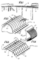
- another preferred embodiment of an individual adaptive panel 22 of the present invention is further shown in FIG. 3.
- the panel 22 has a convex configuration which is generally truncated triangular in cross-section with the internal intersections 36 of the body portion 39 forming angles generally exceeding ninety degrees.
- the body portion 39 is also provided with corrugations 42 generally oriented perpendicular to the longitudinal axis of the panel 22 and generally parallel to the cross-sectional plane of the panel 22.
- This embodiment may further, but need not necessarily, be provided with edge portions 45 attached to the lateral sides of the body portion 39 forming further corrugations 48 oriented parallel to and intersecting or merging with the corrugations 42 of the body portion 39.
- the panel 22 of this embodiment can similarly be expanded and contracted along its entire length or width to adapt the panel 22 to structural support members of varying dimensions without specialized tailoring. Additionally, localized expansion and contraction of the corrugations 42 and 48 permit curvature of the panel 22 so as to adapt to the complex surface curvatures of various structural support members.
Landscapes
- Engineering & Computer Science (AREA)
- Architecture (AREA)
- Civil Engineering (AREA)
- Structural Engineering (AREA)
- Physics & Mathematics (AREA)
- Electromagnetism (AREA)
- Acoustics & Sound (AREA)
- Life Sciences & Earth Sciences (AREA)
- Sustainable Development (AREA)
- Roof Covering Using Slabs Or Stiff Sheets (AREA)
Description
- The present invention concerns architectural structures, and more particularly, relates to an architectural cover panel system for covering structural support members. Architectural cover panels are typically employed to provide aesthetically pleasing coverings over structural support members such as bridge girders and building beam members such as I-beams. These cover panels also provide some protection to the structural support member from the elements and may otherwise serve to seal the underlying support structure from intrusions, such as for example bird nestings.
- Conventional architectural cover panels are generally configured as flat sheets of relatively thick material which are attached to an exposed side of a structural support member. One example of a conventional architectural cover panel is illustrated in U.S. Patent No. 3,538,664 to L. Frandsen et al. Because of their generally planar configuration, conventional architectural cover panels require significant rigidity and strength to resist wind loading forces which could otherwise dismember or dislodge the panel. Accordingly, conventional cover panels can add significant weight to the entire load supported by the underlying structural member.
- Fitting conventional architectural cover panels to a structural support member can also be an expensive, labour and time intensive effort since the panels have to be cut and trimmed in order to fit a variety of complex curves and shapes of the structural support member. Thus, there still exists a need for a lightweight architectural cover panel which is adaptable to the varying dimensions and shapes of differing structural support members but adequately resistant to wind loading forces.
- FR-A-1280028 discloses a pent roofing arrangement using sheet materials, which may, for example, be sheet metal or plastics, and in which two corrugated surfaces slope down from a ridge region of the roof, the corrugation of each corrugated surface extending longitudinally from said roof ridge region to the eaves. Each corrugated surface is of zig-zag form in section perpendicular to the longitudinal direction of its corrugations. In the ridge region of the roof, the two corrugated surfaces are joined in accordion fashion so that the peak of each corrugation on one of the two corrugated surfaces meets the trough of a respective corrugation of the other surface and vice versa.
- Briefly, and in general terms, an object of the present invention is to provide a lightweight architectural cover panel system which is both resistant to wind loading forces and also readily adaptable to structural support members having a variety of dimensions and surface shapes without excessive trimming or cutting of individual panels.
- More specifically, a preferred embodiment of the present invention provides a system of adaptive architectural cover panels made from relatively thin sheet material and formed in a generally convex cross-sectional shape, whether of curved or angular configuration or otherwise. The panels are provided with corrugations lying in the cross-sectional plane, allowing the panel the flexibility to either expand or contract along any desired axis so as to conform to the shape of a structural support member while further providing significant reinforcement against wind loading forces. Adjacent panels may be overlapped or nested at their ends with the result that a plurality of panels can be efficiently and economically joined contiguously to attractively cover the full extent of a complexly shaped structure.
- In one preferred embodiment of the architectural cover panel system of the present invention, the individual panels further may be provided with edge portions projecting from the longitudinal margins or sides of the convex portions of the panels. The edge portions also may be corrugated, with these corrugations lying generally parallel to and intersecting the corrugations of the convex panel portion. The edge portions provide a simple method of attaching the panel to a structural support member and further provide additional resistance to wind loading forces.
- The novel features which are believed to be characteristic of the present invention, together with further objectives and advantages thereof, will be better understood from the following detailed description considered in connection with the accompanying drawings, wherein like numbers designate like elements. It should be expressly understood, however, that the drawings are for purposes of illustration and description only and are not intended as a definition of the limits of the invention.
- FIG. 1 is a perspective view of the adaptive architectural cover panel system of the present invention installed over an illustrative architectural structure;
- FIG. 2 is a perspective view of one preferred embodiment of an individual adaptive architectural cover panel of the present invention;
- FIG. 3 is a perspective view of yet another preferred embodiment of an individual adaptive architectural panel of the present invention;
- FIG. 4 is a perspective view of the individual architectural panel illustrated in FIG. 2 attached to an exemplary structural support member.
- Referring to the figures, and more particularly FIG. 1 thereof, there is shown an illustrative application of the present inventive adaptive architectural panel system 10 covering the edges of
structural support members 13 forming a monorail track and monorail station platform. The ends of adjacent panels 10 may be overlapped and nested to obscure the junctures of the panels and provide a cleaner, more aesthetically appealing architectural appearance to the underlying support members. Although relatively light, and therefore adding little to the load born by thestructural support members 13, the panels 10 are still sufficiently strong to resist normal wind loading. - One preferred embodiment of an
individual panel 16 that forms part of the panel system 10 is more fully illustrated in FIG. 2. As shown, thepanel 16 is made from a square or generally rectangular sheet of relatively thin material and is formed into a panel having a generally convex cross-section. Thepanel 16 is also provided with a plurality ofcorrugations 18, oriented perpendicular to a longitudinal axis of the panel and parallel to the plane of the panel cross-section. Thecorrugations 18 add enhanced flexibility to thepanel 16 while simultaneously providing additional structural reinforcement. The configurations illustrated in FIG. 2 characterize only one type of fold pattern contemplated by the present invention. As illustrated, the corrugations of thepanel 16 provide generally flat surfaces 19 meeting at varying angles with alternating surfaces 20 lying in essentially parallel planes. Other corrugation patterns could also be used such as, for example, where the alternating flat surfaces 20 would lie in non-parallel planes and every third flat surface would lie in the same plane. - The corrugations permit expansion or contraction along the entire width and length of the
panel 16 to accommodatesupport members 13 of varying dimensions, and further allow for localized panel expansion or contraction so as to conform thepanel 16 to the surface curvature of thesupport member 13. Thus, the corrugations allow the sameadaptive cover panel 16 to be used in conjunction with several different types of structural support members of varying dimensions and surface shapes without the need for excessive cutting and trimming. At the same time, however, the corrugations further permit use of lighter materials, such as sheet metals, plastics or composite materials, for the construction of thepanel 16 while still retaining sufficient rigidity to resist wind loading. Thecorrugations 18 also facilitate the overlapping placement ofadjacent panels 16 so as to obscure the junction of thepanels 16 and provide cleaner architectural lines as discussed above. Differences in the thermal expansion coefficients of thepanels 16 andsupport members 13 are also accommodated by the adaptive expansion and contraction of thepanels 16. - In the preferred embodiment illustrated in FIG. 2, the
panel 16 is further provided with edge portions 21 projecting from the longitudinal sides of theconvex body portion 24. The edge portions 21 are also provided withcorrugations 27 which are oriented perpendicular to the longitudinal axis of the panel and thus lie parallel to and intersect with or merge into thecorrugations 18 of theconvex body portion 24. These edge portions 21 permit theadaptive panels 16 to be very easily mounted on to a structural support member while maintaining the adaptive character of thepanel 16 and adding to its wind loading resistance. - As illustrated in FIG. 4, this preferred embodiment of the
panel 16 may be mounted onto an illustrative structural support member 30 by attaching channel members 33 onto the opposing edges of the support member 30. The edge portions 21 of the panel 10 may then be affixed within the channels 33 by any convenient means such as, for example, suitable fasteners. It should be understood that for the purposes of the present invention, however, thepanel 16 could also be directly attached to the structural support member 30. - The present inventive adaptive architectural cover panel need not be restricted to convex configurations which are generally curved in cross-section such as the
panel 16 shown in FIG. 2. By way of illustration, another preferred embodiment of an individualadaptive panel 22 of the present invention is further shown in FIG. 3. In this embodiment thepanel 22 has a convex configuration which is generally truncated triangular in cross-section with theinternal intersections 36 of the body portion 39 forming angles generally exceeding ninety degrees. The body portion 39 is also provided with corrugations 42 generally oriented perpendicular to the longitudinal axis of thepanel 22 and generally parallel to the cross-sectional plane of thepanel 22. This embodiment may further, but need not necessarily, be provided withedge portions 45 attached to the lateral sides of the body portion 39 forming further corrugations 48 oriented parallel to and intersecting or merging with the corrugations 42 of the body portion 39. As with the embodiment discussed above in connection with FIG. 2, thepanel 22 of this embodiment can similarly be expanded and contracted along its entire length or width to adapt thepanel 22 to structural support members of varying dimensions without specialized tailoring. Additionally, localized expansion and contraction of the corrugations 42 and 48 permit curvature of thepanel 22 so as to adapt to the complex surface curvatures of various structural support members. - It will, of course, be understood that modifications of the present invention will be apparent to others skilled in the art.
Claims (5)
Applications Claiming Priority (2)
| Application Number | Priority Date | Filing Date | Title |
|---|---|---|---|
| US17451688A | 1988-03-28 | 1988-03-28 | |
| US174516 | 1988-03-28 |
Publications (2)
| Publication Number | Publication Date |
|---|---|
| EP0335321A1 EP0335321A1 (en) | 1989-10-04 |
| EP0335321B1 true EP0335321B1 (en) | 1992-07-22 |
Family
ID=22636457
Family Applications (1)
| Application Number | Title | Priority Date | Filing Date |
|---|---|---|---|
| EP19890105435 Expired EP0335321B1 (en) | 1988-03-28 | 1989-03-28 | Adaptive architectural cover panel system |
Country Status (3)
| Country | Link |
|---|---|
| EP (1) | EP0335321B1 (en) |
| DE (1) | DE68902156T2 (en) |
| ES (1) | ES2033038T3 (en) |
Families Citing this family (4)
| Publication number | Priority date | Publication date | Assignee | Title |
|---|---|---|---|---|
| DE4019022A1 (en) * | 1990-02-03 | 1992-01-02 | Friedhelm Boltz | Self-supporting building structure - comprises several prefab. base parts formed as two-track folding constructions |
| DE4003185A1 (en) * | 1990-02-03 | 1991-08-08 | Friedhelm Boltz | Self-supporting building - is produced from two thin strips which are folded in zigzag fashion and fastened together |
| US7051489B1 (en) | 1999-08-12 | 2006-05-30 | Hunter Douglas Inc. | Ceiling system with replacement panels |
| NL1013311C2 (en) * | 1999-10-15 | 2001-04-18 | Jansen Kunststoffen B V | Sound-absorbing module, sound-absorbing screen or wall and method for the manufacture of the sound-absorbing module. |
Family Cites Families (2)
| Publication number | Priority date | Publication date | Assignee | Title |
|---|---|---|---|---|
| FR1280028A (en) * | 1960-11-14 | 1961-12-29 | Pleated roof | |
| FR1340142A (en) * | 1962-12-05 | 1963-10-11 | Caboshed Invest Ltd | Tunnel-shaped construction |
-
1989
- 1989-03-28 DE DE1989602156 patent/DE68902156T2/en not_active Expired - Lifetime
- 1989-03-28 EP EP19890105435 patent/EP0335321B1/en not_active Expired
- 1989-03-28 ES ES89105435T patent/ES2033038T3/en not_active Expired - Lifetime
Also Published As
| Publication number | Publication date |
|---|---|
| EP0335321A1 (en) | 1989-10-04 |
| DE68902156T2 (en) | 1993-02-18 |
| DE68902156D1 (en) | 1992-08-27 |
| ES2033038T3 (en) | 1993-03-01 |
Similar Documents
| Publication | Publication Date | Title |
|---|---|---|
| US5367848A (en) | Bracket | |
| EP0396606B1 (en) | Laminated roofing hip | |
| EP0551415B1 (en) | Adaptive bidirectional architectural cover system | |
| US6223481B1 (en) | Roof construction | |
| CA1256263A (en) | Roofs | |
| US6314698B1 (en) | Cladding panels of sheet metal or similar material for forming a coffered ceiling and a method for assembling of such panels | |
| EP1017910B1 (en) | Roof cladding element, system and use of the elements | |
| EP0335321B1 (en) | Adaptive architectural cover panel system | |
| US4958476A (en) | Adaptive architectural cover panel system | |
| US4777776A (en) | Roof panel construction | |
| GB2176218A (en) | Roofing panels | |
| JPS6225655A (en) | Self-erecting constitutional element for forming roof surface | |
| US20010039767A1 (en) | Cladding for a domed structure | |
| KR100683958B1 (en) | Improvements in and relating to roofing or sheathing | |
| EP0126719A2 (en) | A roofing element | |
| US6293070B1 (en) | Cladding for a domed structure | |
| JPH06240840A (en) | Lining of panel of external surface of wall | |
| WO1997040240A1 (en) | Panel for roofs | |
| JPS6242013Y2 (en) | ||
| JPH09195439A (en) | Arc-shaped building material and arch structure using it | |
| JPS6132044Y2 (en) | ||
| JPH0243132Y2 (en) | ||
| JP3628177B2 (en) | Horizontal roof and its construction method | |
| SU1036871A1 (en) | Filler for multiple-layer panel | |
| EP0228296A2 (en) | Roofing panel |
Legal Events
| Date | Code | Title | Description |
|---|---|---|---|
| PUAI | Public reference made under article 153(3) epc to a published international application that has entered the european phase |
Free format text: ORIGINAL CODE: 0009012 |
|
| AK | Designated contracting states |
Kind code of ref document: A1 Designated state(s): CH DE ES IT LI |
|
| 17P | Request for examination filed |
Effective date: 19900404 |
|
| 17Q | First examination report despatched |
Effective date: 19910404 |
|
| ITF | It: translation for a ep patent filed | ||
| GRAA | (expected) grant |
Free format text: ORIGINAL CODE: 0009210 |
|
| AK | Designated contracting states |
Kind code of ref document: B1 Designated state(s): CH DE ES IT LI |
|
| REF | Corresponds to: |
Ref document number: 68902156 Country of ref document: DE Date of ref document: 19920827 |
|
| REG | Reference to a national code |
Ref country code: ES Ref legal event code: FG2A Ref document number: 2033038 Country of ref document: ES Kind code of ref document: T3 |
|
| PLBE | No opposition filed within time limit |
Free format text: ORIGINAL CODE: 0009261 |
|
| STAA | Information on the status of an ep patent application or granted ep patent |
Free format text: STATUS: NO OPPOSITION FILED WITHIN TIME LIMIT |
|
| 26N | No opposition filed | ||
| PGFP | Annual fee paid to national office [announced via postgrant information from national office to epo] |
Ref country code: CH Payment date: 20080328 Year of fee payment: 20 Ref country code: ES Payment date: 20080326 Year of fee payment: 20 |
|
| PGFP | Annual fee paid to national office [announced via postgrant information from national office to epo] |
Ref country code: DE Payment date: 20080430 Year of fee payment: 20 |
|
| PGFP | Annual fee paid to national office [announced via postgrant information from national office to epo] |
Ref country code: IT Payment date: 20080329 Year of fee payment: 20 |
|
| REG | Reference to a national code |
Ref country code: CH Ref legal event code: PL |
|
| REG | Reference to a national code |
Ref country code: ES Ref legal event code: FD2A Effective date: 20090330 |
|
| PG25 | Lapsed in a contracting state [announced via postgrant information from national office to epo] |
Ref country code: ES Free format text: LAPSE BECAUSE OF EXPIRATION OF PROTECTION Effective date: 20090330 |