EP0335174A2 - Grain polishing machine - Google Patents
Grain polishing machine Download PDFInfo
- Publication number
- EP0335174A2 EP0335174A2 EP89104603A EP89104603A EP0335174A2 EP 0335174 A2 EP0335174 A2 EP 0335174A2 EP 89104603 A EP89104603 A EP 89104603A EP 89104603 A EP89104603 A EP 89104603A EP 0335174 A2 EP0335174 A2 EP 0335174A2
- Authority
- EP
- European Patent Office
- Prior art keywords
- polishing
- grain
- rotor
- chamber
- cylinder
- Prior art date
- Legal status (The legal status is an assumption and is not a legal conclusion. Google has not performed a legal analysis and makes no representation as to the accuracy of the status listed.)
- Granted
Links
- 238000005498 polishing Methods 0.000 title claims abstract description 243
- 239000000463 material Substances 0.000 claims description 6
- 238000011144 upstream manufacturing Methods 0.000 claims 1
- 239000002245 particle Substances 0.000 description 64
- 230000000694 effects Effects 0.000 description 12
- 230000002159 abnormal effect Effects 0.000 description 2
- 239000000428 dust Substances 0.000 description 2
- 230000002093 peripheral effect Effects 0.000 description 2
- 238000003825 pressing Methods 0.000 description 2
- 230000002787 reinforcement Effects 0.000 description 2
- 238000009423 ventilation Methods 0.000 description 2
- 238000013019 agitation Methods 0.000 description 1
- 230000007423 decrease Effects 0.000 description 1
- 230000003247 decreasing effect Effects 0.000 description 1
- 230000006866 deterioration Effects 0.000 description 1
- 238000009434 installation Methods 0.000 description 1
- 230000005923 long-lasting effect Effects 0.000 description 1
- 238000000034 method Methods 0.000 description 1
- 239000000203 mixture Substances 0.000 description 1
- 230000000452 restraining effect Effects 0.000 description 1
- 230000002441 reversible effect Effects 0.000 description 1
- 238000003466 welding Methods 0.000 description 1
Images


Classifications
-
- B—PERFORMING OPERATIONS; TRANSPORTING
- B02—CRUSHING, PULVERISING, OR DISINTEGRATING; PREPARATORY TREATMENT OF GRAIN FOR MILLING
- B02B—PREPARING GRAIN FOR MILLING; REFINING GRANULAR FRUIT TO COMMERCIAL PRODUCTS BY WORKING THE SURFACE
- B02B3/00—Hulling; Husking; Decorticating; Polishing; Removing the awns; Degerming
- B02B3/04—Hulling; Husking; Decorticating; Polishing; Removing the awns; Degerming by means of rollers
-
- B—PERFORMING OPERATIONS; TRANSPORTING
- B02—CRUSHING, PULVERISING, OR DISINTEGRATING; PREPARATORY TREATMENT OF GRAIN FOR MILLING
- B02B—PREPARING GRAIN FOR MILLING; REFINING GRANULAR FRUIT TO COMMERCIAL PRODUCTS BY WORKING THE SURFACE
- B02B3/00—Hulling; Husking; Decorticating; Polishing; Removing the awns; Degerming
Definitions
- the present invention relates to a vertical shaft and friction type grain polishing machine in which grain particles are supplied into a polishing chamber from one end thereof and polished grain particles are discharged from the other end of the polishing chamber.
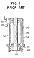
- Fig. 1 is a sectional view of a known polishing machine of vertical shaft and friction type.
- Grain particles are supplied from a grain supplying section (not shown) to a grain feeding chamber 102 formed around a spiral rotor 101 fixed to a main shaft 109.
- the spiral rotor 101 feeds the grain particles into a polishing chamber 105 which is defined by a friction polishing roller 103 and a bran removing polishing cylinder 104 having a perforated wall.
- the grain particles are polished by the frictional polishing effect produced by the frictional polishing roller 103 and the thus polished grain particles are discharged to the outside of the machine through a grain discharge section 106 overcoming the pressure produced by a pressing plate 107.
- Fine dust such as bran produced as a result of the polishing performed in the polishing chamber is carried by air blowen from elongated slots 108 to the exterior of the machine through the perforation in the perforated wall of the bran removing polishing cylinder 104 and past the bran removing chamber (not shown).
- This known grain polishing machine of vertical shaft and friction type is disadvantageous in that insufficient agitation and mixture of grain particles take place because the pressure is uniformly applied to the grain particles in the polishing chamber 105 in the direction of the axis of the vertical shaft. In consequence, it is experienced that a part of grain particles are discharged before they are satisfactorily polished, resulting in a non-uniform polishing of the grain.
- a resistance pressure posed on the grain particles in the machine can be increased by means of a pressing plate which is controlled by a resistance control device, such increase does not provide any appreciable effect in the polishing because grain particles do not revolve so as to make friction among grain particles null, and only the grain temperature rises at most.
- the known grain polishing machine of vertical shaft and friction type could provide only a low polishing efficiency and yield of the polished grain.
- an object of the present invention is to provide a vertical shaft and friction type grain polishing machine which is capable of imparting sufficient agitating and mixing effects to grain particles so as to avoid variation in polishing of again particles thus preventing polishing efficiency and yield from decreasing, thereby to overcome the above-described problems of the prior art.
- a grain polishing machine of vertical shaft and friction type comprising: a vertical perforated bran removing polishing cylinder, a main shaft rotatably mounted in said cylinder, and a spiral rotor and a polishing rotor mounted by said main shaft for rotation therewith, said polishing, rotor having agitating projections, said perforated bran removing polishing cylinder and said polishing rotor cooperating with each other define a polishing chamber therebetween which is communicated with a grain feed section and a grain discharge section at its one and the other ends thereof, wherein each of the perforated bran removing polishing cylinder and said polishing rotor is composed of a plurality of portions having different diameters.
- the grain feed section is formed at the lower end of the polishing chamber.
- the grain feed section is connected to a feed chamber and a grain supply device for compulsorily feeding the grain particles is connected to the grain feed section.
- a resistance adjusting means capable of adjusting the cross-sectional area of the space between the polishing rotor and the polishing cylinder is disposed at a stepped portion of the cylinder where the diameter of the cylinder is changed.
- the maximum diameter portion of the agitating projections of the polishing rotor is made of a wear-resistant material which is different from the material of remaining portion thereof.
- the agitating projections are inclined at an angle to the vertical axis of the polishing rotor such that the upper parts of the agitating projections has a lag angle in the direction of rotation of the polishing rotor.
- each stepped portion of the polishing rotor are stepped at a right angle.
- the perforated polishing cylinder has elongated holes a part or all of which are inclined with respect to the direction of rotation of the polishing rotor such that the grain particles are led and thrusted towards the grain discharge section.
- the grain particles fed to the spiral rotor from the grain feed section are fed into the polishing chamber defined mainly by the perforated bran removing polishing cylinder and the polishing rotor so as to be polished.
- the thus polished grain particles are discharged from the grain discharge section so as to be delivered to a next process station.
- the pressure applied to the grain particles is changed as the grain particles passes the portion of the polishing chamber where the polishing cylinder and the polishing rotor are stepped so that a large mixing effect and strong agitating effect are caused on the grain particles to enable the grain particles to remove in the polishing chamber, whereby the grain particles are satisfactorily polished in the polishing chamber.
- the grain particles are fed from the lower side of the polishing chamber and are discharged from the upper side of the same.
- the grain particles are compulsorily fed from the grain feed section by means of the grain supply device.
- the cross-sectional area of the passage defined by the stepped portions of the polishing cylinder and the polishing rotor is adjusted by the resistance adjusting means so as to control the polishing pressure developed in the polishing chamber.
- any deterioration in the polishing performance due to wear of the agitating projections is remarkably suppressed.
- an upward thrust or lift is imparted to the grain particles by the polishing rotor provided with inclined agitating projections so that the grain particles are polished with pressure being well-balanced between in upper and lower sections.
- the polishing pressure in the polishing chamber is unsmoothly changed due to the presence of the stepped portions.
- the grain particles are led and thrusted towards the discharge section by virtue of the elongated holes which are provided in the polishing cylinder at inclination.
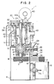
- Fig. 2 is a sectional side elevational view of a vertical shaft and friction type grain polishing machine of the present invention.
- the vertical shaft and friction type polishing device of the present invention which is generally denoted by a numeral 1, has a perforated bran removing polishing cylinder 2 having an upper portion of a larger diameter and a lower portion of a smaller diameter.
- a main shaft 3 is rotatably disposed in the polishing cylinder 2.
- the main shaft 3 is rotatably supported at its upper and lower portions through upper and lower bearings 4, 5 on a frame 7 on a base box 6.
- a spiral rotor 8 is mounted on an intermediate lower portion of the main shaft 3 for rotation therewith.
- the main shaft 3 also carries, at its portion above the spiral rotor 8, a lower friction polishing rotor 9 and an upper friction polishing rotor 10 which are formed thereon with agitating projections 36.
- the perforated bran removing polishing cylinder 2, and the friction polishing rotors 9, 10 in cooperation define a lower polishing chamber 11 and an upper polishing chamber 12.
- the lower polishing chamber 11 communicates at its lower end portion with a grain feed section 14 through a feed chamber 13 which is defined around the spiral rotor 8.
- the upper polishing chamber 12 communicates at its upper portion with a discharge section 15.
- a reference numeral 16 denotes a main motor for driving the vertical shaft and friction type polishing machine.
- the motor 16 is mounted on the base box 6 by means of mounting means 17a.
- the motor 16 has a motor pulley 17 which is drivingly connected to the pulley 18 on the main shaft 3 through V-belts 19.
- the upper friction polishing rotor 10 has a diameter greater than that of the lower polishing rotor 9 so that a step is formed at the boundary between both polishing rotors 9 and 10.
- the perforated polishing cylinder 2 surrounds both polishing rotors 9 and 10 so as to define an upper polishing chamber 12 and a lower polishing chamber 11.
- the perforated polishing cylinder 2 is stepped at a portion thereof corresponding to the step between the upper and lower polishing rollers such that the portion thereof above the step has a greater diameter than the portion thereof below the step.
- the upper polishing chamber 12 and the lower polishing chamber 11 are connected indirectly through a connecting portion defined by the steps of the cylinder and polishing rotors.
- the resistance adjusting device 20 has a resistance plate 21 which is connected to the rack 23 through a lever 22 made of an elastic member.
- the rack 23 is drivingly connected to a reversible electric motor 24 through a gear train 25, 25′, 25 ⁇ (see Fig. 3).
- the lever 22 is rotated about the shaft 26 of the resistance plate so that the resistance plate 21 is rotated relatively to the grain discharge section 15.
- a conduit 27 is connected to the downstream side of the grain discharge section 15 and a discharge chute 28 is connected to the conduit 27.
- a grain supply device 30 connected to a supply hopper 29 has a rotor which is composed of a conveyor shaft 31 and a screw member 32 provided around the conveyor shaft 31.
- a pulley 33 secured to the conveyor shaft 31 is drivingly connected through a V-belt 38 to a pulley 37 on an electric motor 35 which is provided on a bracket 34 secured to the base box 6.
- the grain supply device 30 is communicated with the feed section 14.
- the main shaft 3 is hollow and is provided with a multiplicity of ventilation ports 39 provided in the portion thereof facing the polishing rotors 9, 10 there around.
- the hollow cavity of the main shaft 3 is connected to the air outlet 40a of a blower device 40.
- the main shaft 3 is designed to rotate relative to the air discharge end of the air outlet 40a of the blower device 40 which faces the main shaft 30, so that a slight gap is left between the end of the air outlet 40a and the end of the main shaft 3.
- the internal cavity of the main shaft 3 is opened at its upper end while the lower end thereof is closed.
- a reference numeral 41 denotes elongated slots provided on the friction polishing rotors 9, 10.
- a bran removing chamber 42 is connected to a suitable device such as a cyclone through a bran removing duct 43.
- Fig. 4 shows a resistance device 44 for use in connection with the lower polishing chamber 11.
- the resistance device 44 includes a telescopic structure which is realized by a tapered wall portion between the upper and lower portions of the perforated wall of the polishing cylinder 2, the tapered wall portion being slidable into and out of the upper and lower portions of the cylinder 2.
- the tapered wall portion serves as a resistance plate 45 of the resistance device 44 which operates in connection with the lower polishing chamber 11.
- the resistance plate 45 is slidingly driven by the actuator of the resistance device 44 so as to vary the cross-sectional area of the connecting portion which interconnects the upper and lower polishing chambers 11 and 12 and which is disposed around the step between the upper and lower polishing rotors 9 and 10, thereby controlling the level of the resistance posed on the flow of the grain particles, thus enabling the polishing pressure in the lower polishing chamber to be adjusted.
- the grain particles are fed to the grain supply device 30 through the feed hopper 29.
- the grain particles are fed to the spiral rotor 8 by means of the screw 32 and is lifted to the lower polishing chamber 11 by the spiral rotor 8.
- the grain particles are polished by the polishing action effected by the rotation of the lower friction polishing rotor 9 and is fed into the upper polishing chamber 12 so as to be polished by the upper polishing rotor 10.
- the grain particles move from the lower polishing chamber 11 into the upper polishing chamber 12 across the connecting portion as a boundary part therebetween, the grain particles experience a change in the polishing pressure.
- the grain polishing machine of this embodiment exhibits high polishing efficiency and improved polishing performance.
- the step formed between the lower friction polishing roller 9 and the upper friction polishing roller 10 having the greater diameter than the lower friction polishing roller 9 serves to interrupt or restrict the direct communication between the upper polishing chamber 12 and the lower polishing chamber 11, so that the weight of the grain particles residing in the upper polishing chamber 12 is not directly applied to the grain particles in the lower polishing chamber 11, so that the grain particles in the lower polishing chamber 11 is relieved from any excessive pressure, thus obviating any tendency for the grain particles to be clacked or crushed.
- bran removing air is blows from the air nozzle 41 of the blower 41 into the polishing chambers 11 and 12 through the ventilation holes 39, thereby removing bran.
- Dust containing bran produced in the polishing chambers 11 and 12 during polishing is discharged into the bran removing chamber 42 through the perforations in the perforate bran removing polishing cylinder 2 and is sent to a suitable collecting device such as a cyclone (not shown) through the bran removing chamber 42 and the bran removing duct 43.
- the polished grain particles then reach the grain discharge section 15 where the resistance plate 21 of the automatic resistance adjusting device 20 is provided so as to restrict the outcoming flow of the grain particles.
- the degree of polishing is adjustable by the level of the resistance posed by the resistance plate 21.
- the polished grain particles are forcibly discharged overcoming the pressure posed by the resistance plate 21 to the exterior of the machine through the conduit 27 and the chute 28.
- the degree of resistance posed by the resistance adjusting device 20 is varied depending on the types of the grain particles.
- the upper polishing chamber 12 and the lower polishing chamber 11 are connected through the connecting portion which is restricted due to the presence of the step between the upper and lower polishing rotors 9 and 10, so that the polishing pressure existing in the upper polishing chamber is not directly transmitted to the lower polishing chamber 11. Therefore, any change in the resistance posed by the resistance plate 21 on the outlet end of the upper polishing chamber does not cause any substantial change in the polishing pressure in the lower polishing chamber 11.
- the porous resistance plate 45 of the resistance device 44 is moved by an actuating means similar to that shown in Fig. 3, through a rack 49 and a pinion 50, so as to vary the cross-sectional area of a connecting passage 46 in the connecting portion through which the lower and upper polishing chamber 11 and 12 are communicates with each other as shown in Fig. 4, thereby adjusting the polishing pressure in the lower polishing chamber 11.
- the porous wall resistance plate 45 is adjusted to a position where the gap A of the connection passage 46 is obtained.
- the porous resistance plate 45 is also adjustable to positions B and C, respectively, when polishing a grain which is rather hard to be polished and a grain which is liable to be clacked or crushed.
- the agitating projections 36 wear as the polishing time becomes long.
- the wear of the agitating projections tend to impair the agitating effect with the result that the polishing efficiency is seriously lowered.
- a reinforcement member 47 made of a wear-resistant material is therefore secured to each agitating projection 36 as shown in Figs. 5 and 6, thus preventing rapid wear of the agitating projections.
- the reinforcement member may be permanentally fixed by, for example, welding or may be attached replaceably.
- each agitating projection is mounted such as to extend in the vertical direction as shown in Fig. 5, there is a tendency that the pressure becomes high in the lower regions of the polishing chambers 11 and 12 and low in the higher regions of these chambers, so that the grain particles are liable to be polished excessively, i.e., ground or crushed, in the lower regions of the respective polishing chambers 11 and 12.
- the agitating projections 36A and 36B are inclined at an angle to the axis of the friction polishing rotors 9 and 10 such that the upper end portions of these projections lag as viewed in the direction R of rotation of the friction polishing rotors 9, 10.
- the grain particles therefore, are lifted by the agitating projections 36A and 36B against the weight of the grain particles themselves, so that the polishing pressure is well-balanced in the vertical direction in each of the polishing chambers 11 and 12, thus suppressing any tendency of excessive polishing of the grain particles in each polishing chamber.
- step X between the upper friction polishing rotor 10 and the lower friction polishing rotor 9 is perpendicular to the axis of these rotor as shown in Fig. 5, the grain particles which move from the lower polishing chamber 11 into the upper polishing chamber 12 experience a large change in the resistance, thereby making it possible to cause a significant change in the polishing pressure applied to the lower polishing chamber 11.
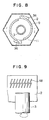
- the multiplicity of holes formed in the wall of the perforated bran removing polishing cylinder 2 are elongated holes which are inclined at a predetermined angle to the direction of rotation of the polishing rotors in such a direction as to lead and thrust the grain particles towards the discharge end.
- the elongated holes produce a kind of lifting effect so as to attain a balance of the polishing pressure in the vertical direction, thus avoiding any tendency of excessive polishing, i.e., grinding or crushing, of the grain particles.
- the polishing rotor is composed of two independent rotors having different diameters, while the polishing cylinder also has upper and lower portions of different diameters.
- the polishing cylinder, as well as the polishing rotor may have three or more portions of different diameters.
- the upper polishing rotor 10 has a diameter which is greater than that of the lower polishing roller 9. This, however, is not exclusive and the arrangement may be such that the lower polishing rotor 9 has a greater diameter than the upper polishing rotor 10.
- each of the perforated polishing cylinder and the polishing rotor is composed of a plurality of portions having different diameters, the grain particles moving from one to another polishing chambers across the boundary portion encounters a pressure which temporarily rises in the region around the boundary portion between the polishing chambers of different diameters and then drastically decreases.
- the grain particles polished in the polishing chamber undergoe a variation in the pressure so that they are agitated satisfactorily.
- polishing rotors of different diameters rotate at the same speed, different peripheral speeds are obtained on the peripheral surfaces of these rotors, whereby different levels of polishing effect are obtained to prevent any uneven polishing and consequent imperfect polishing of the grain particles.
- an effective friction polishing effect is produced so as to improve the polishing efficiency.
- the feed section is provided on the lower end of the machine so that, when a plurality of polishing machines are arranged in stages, the grain particles are supplied to the next stage of the polishing machine without necessitating any grain lifting device, thus achieving a remarkable reduction in the installation cost.
- the grain particles are forcibly or compulsorily introduced into the machine by means of the grain supply device, so that the flow of the grain particles entering the machine is rendered steady so as to ensure a stable polishing effect, thereby remarkably increasing the polishing capacity.
- the polishing pressure applied to the grain particles in the lower polishing chamber is controlled by means of the resistance device which is capable of adjusting the cross-sectional area of the connecting passage in the boundary between the upper and lower polishing cylinders, thus adapting the grain polishing machine to a variety of types and classes of grains.
- the agitating projections are made at least partially from a wear-resistant material so that the agitating projections can stand a long use by preventing the agitating projections from being worn down soon, thus ensuring a long-lasting high polishing efficiency of the grain polishing machine.
- the agitating projections are inclined at an angle to the direction of the axis of the polishing rotor such that the downstream portion of the agitating projection lags as viewed in the direction of rotation of the rotor, so that the polishing pressure is well-balanced in the vertical direction so as to prevent any crushing of the grain particles which may otherwise be caused due to locally abnormal increase in the polishing pressure.
- the step of the polishing rotor is formed substantially perpendicularly to the axis of the polishing rotor so that the grain particles moving across the step encounters a drastic change in the pressure. This step also facilitates adjustment of pressure in each polishing chamber.
- the elongated holes formed in the wall of the perforated bran removing polishing chamber are inclined with respect to the direction of rotation of the polishing rotor such that these holes lead and thrust the grain particles towards the discharge side. Therefore, these holes provide a lifting effect on the grain particles so that balance of the polishing pressure is attained in the vertical direction in each of the polishing chamber thereby to eliminate any thendency for the grain particles to be excessively polished or ground, thus preventing any reduction in the yield which may otherwise be caused by the excessive polishing.
Landscapes
- Adjustment And Processing Of Grains (AREA)
Abstract
Description
- The present invention relates to a vertical shaft and friction type grain polishing machine in which grain particles are supplied into a polishing chamber from one end thereof and polished grain particles are discharged from the other end of the polishing chamber.
- Fig. 1 is a sectional view of a known polishing machine of vertical shaft and friction type. Grain particles are supplied from a grain supplying section (not shown) to a
grain feeding chamber 102 formed around aspiral rotor 101 fixed to amain shaft 109. Thespiral rotor 101 feeds the grain particles into apolishing chamber 105 which is defined by afriction polishing roller 103 and a bran removing polishingcylinder 104 having a perforated wall. The grain particles are polished by the frictional polishing effect produced by thefrictional polishing roller 103 and the thus polished grain particles are discharged to the outside of the machine through agrain discharge section 106 overcoming the pressure produced by apressing plate 107. Fine dust such as bran produced as a result of the polishing performed in the polishing chamber is carried by air blowen fromelongated slots 108 to the exterior of the machine through the perforation in the perforated wall of the bran removingpolishing cylinder 104 and past the bran removing chamber (not shown). - This known grain polishing machine of vertical shaft and friction type, however, is disadvantageous in that insufficient agitation and mixture of grain particles take place because the pressure is uniformly applied to the grain particles in the
polishing chamber 105 in the direction of the axis of the vertical shaft. In consequence, it is experienced that a part of grain particles are discharged before they are satisfactorily polished, resulting in a non-uniform polishing of the grain. In this known grain polishing machine, although a resistance pressure posed on the grain particles in the machine can be increased by means of a pressing plate which is controlled by a resistance control device, such increase does not provide any appreciable effect in the polishing because grain particles do not revolve so as to make friction among grain particles null, and only the grain temperature rises at most. Thus, the known grain polishing machine of vertical shaft and friction type could provide only a low polishing efficiency and yield of the polished grain. - Accordingly, an object of the present invention is to provide a vertical shaft and friction type grain polishing machine which is capable of imparting sufficient agitating and mixing effects to grain particles so as to avoid variation in polishing of again particles thus preventing polishing efficiency and yield from decreasing, thereby to overcome the above-described problems of the prior art.
- According to a first aspect of the present invention, there is provided a grain polishing machine of vertical shaft and friction type comprising: a vertical perforated bran removing polishing cylinder, a main shaft rotatably mounted in said cylinder, and a spiral rotor and a polishing rotor mounted by said main shaft for rotation therewith, said polishing, rotor having agitating projections, said perforated bran removing polishing cylinder and said polishing rotor cooperating with each other define a polishing chamber therebetween which is communicated with a grain feed section and a grain discharge section at its one and the other ends thereof, wherein each of the perforated bran removing polishing cylinder and said polishing rotor is composed of a plurality of portions having different diameters.
- According to a second aspect of the invention, the grain feed section is formed at the lower end of the polishing chamber.
- According to a third aspect of the present invention, the grain feed section is connected to a feed chamber and a grain supply device for compulsorily feeding the grain particles is connected to the grain feed section.
- According to a fourth aspect of the present invention, a resistance adjusting means capable of adjusting the cross-sectional area of the space between the polishing rotor and the polishing cylinder is disposed at a stepped portion of the cylinder where the diameter of the cylinder is changed.
- According to a fifth aspect of the present invention, the maximum diameter portion of the agitating projections of the polishing rotor is made of a wear-resistant material which is different from the material of remaining portion thereof.
- According to a sixth aspect of the present invention, the agitating projections are inclined at an angle to the vertical axis of the polishing rotor such that the upper parts of the agitating projections has a lag angle in the direction of rotation of the polishing rotor.
- According to a seventh aspect of the present invention, each stepped portion of the polishing rotor are stepped at a right angle.
- According to an eighth aspect of the present invention, the perforated polishing cylinder has elongated holes a part or all of which are inclined with respect to the direction of rotation of the polishing rotor such that the grain particles are led and thrusted towards the grain discharge section.
- In the grain polishing machine in accordance with the first aspect of the present invention, the grain particles fed to the spiral rotor from the grain feed section are fed into the polishing chamber defined mainly by the perforated bran removing polishing cylinder and the polishing rotor so as to be polished. The thus polished grain particles are discharged from the grain discharge section so as to be delivered to a next process station. Meanwhile, the pressure applied to the grain particles is changed as the grain particles passes the portion of the polishing chamber where the polishing cylinder and the polishing rotor are stepped so that a large mixing effect and strong agitating effect are caused on the grain particles to enable the grain particles to remove in the polishing chamber, whereby the grain particles are satisfactorily polished in the polishing chamber.
- In the grain polishing machine in accordance with the second aspect of the present invention, the grain particles are fed from the lower side of the polishing chamber and are discharged from the upper side of the same.
- In the grain polishing machine in accordance with the third aspect of the present invention, the grain particles are compulsorily fed from the grain feed section by means of the grain supply device.
- In the grain polishing machine in accordance with the fourth aspect of the present invention, the cross-sectional area of the passage defined by the stepped portions of the polishing cylinder and the polishing rotor is adjusted by the resistance adjusting means so as to control the polishing pressure developed in the polishing chamber.
- In the grain polishing machine in accordance with the fifth aspect of the present invention, any deterioration in the polishing performance due to wear of the agitating projections is remarkably suppressed.
- In the grain polishing machine in accordance with the sixth aspect of the present invention, an upward thrust or lift is imparted to the grain particles by the polishing rotor provided with inclined agitating projections so that the grain particles are polished with pressure being well-balanced between in upper and lower sections.
- In the grain polishing machine in accordance with the seventh aspect of the present invention, the polishing pressure in the polishing chamber is unsmoothly changed due to the presence of the stepped portions.
- In the grain polishing apparatus in accordance with the eighth aspect of the present invention, the grain particles are led and thrusted towards the discharge section by virtue of the elongated holes which are provided in the polishing cylinder at inclination.
- The invention will be more fully understood from the following description of the preferred embodiments when the same is read in conjunction with the accompanying drawings.
-
- Fig. 1 is an illustration of a conventional grain polishing machine;
- Fig. 2 is a sectional side elevational view of a vertical shaft and friction type grain polishing machine;
- Fig. 3 is a top plan view of an actuator for a resistance plate;
- Fig. 4 is an illustration of a resistance adjusting device;
- Fig. 5 is a front elevational view of a friction polishing rotor;
- Fig. 6 is a partial side elevational view of agitating projection;
- Figs. 7 and 8 are illustrations of inclined agitating projections; and
- Fig. 9 is an enlarged view of a portion of a polishing cylinder.
- Fig. 2 is a sectional side elevational view of a vertical shaft and friction type grain polishing machine of the present invention. The vertical shaft and friction type polishing device of the present invention, which is generally denoted by a
numeral 1, has a perforated bran removingpolishing cylinder 2 having an upper portion of a larger diameter and a lower portion of a smaller diameter. Amain shaft 3 is rotatably disposed in thepolishing cylinder 2. Themain shaft 3 is rotatably supported at its upper and lower portions through upper andlower bearings 4, 5 on aframe 7 on abase box 6. Aspiral rotor 8 is mounted on an intermediate lower portion of themain shaft 3 for rotation therewith. Themain shaft 3 also carries, at its portion above thespiral rotor 8, a lowerfriction polishing rotor 9 and an upperfriction polishing rotor 10 which are formed thereon withagitating projections 36. - The perforated bran removing
polishing cylinder 2, and thefriction polishing rotors upper polishing chamber 12. The lower polishing chamber 11 communicates at its lower end portion with agrain feed section 14 through afeed chamber 13 which is defined around thespiral rotor 8. Theupper polishing chamber 12 communicates at its upper portion with adischarge section 15. Areference numeral 16 denotes a main motor for driving the vertical shaft and friction type polishing machine. Themotor 16 is mounted on thebase box 6 by means of mounting means 17a. - The
motor 16 has amotor pulley 17 which is drivingly connected to thepulley 18 on themain shaft 3 through V-belts 19. - The upper
friction polishing rotor 10 has a diameter greater than that of thelower polishing rotor 9 so that a step is formed at the boundary between bothpolishing rotors polishing cylinder 2 surrounds bothpolishing rotors upper polishing chamber 12 and a lower polishing chamber 11. The perforatedpolishing cylinder 2 is stepped at a portion thereof corresponding to the step between the upper and lower polishing rollers such that the portion thereof above the step has a greater diameter than the portion thereof below the step. Thus, theupper polishing chamber 12 and the lower polishing chamber 11 are connected indirectly through a connecting portion defined by the steps of the cylinder and polishing rotors. - An automatic
resistance adjusting device 20, which is disposed in thedischarge section 15, is capable of restraining the grain particles discharged from thedischarge section 15. Theresistance adjusting device 20 has aresistance plate 21 which is connected to therack 23 through alever 22 made of an elastic member. Therack 23 is drivingly connected to a reversibleelectric motor 24 through agear train rack 23 moves horizontally by the normal or reversel operation of theservomotor 24, thelever 22 is rotated about theshaft 26 of the resistance plate so that theresistance plate 21 is rotated relatively to thegrain discharge section 15. - A
conduit 27 is connected to the downstream side of thegrain discharge section 15 and adischarge chute 28 is connected to theconduit 27. - A grain supply device 30 connected to a
supply hopper 29 has a rotor which is composed of aconveyor shaft 31 and ascrew member 32 provided around theconveyor shaft 31. Apulley 33 secured to theconveyor shaft 31 is drivingly connected through a V-belt 38 to apulley 37 on anelectric motor 35 which is provided on abracket 34 secured to thebase box 6. The grain supply device 30 is communicated with thefeed section 14. - The
main shaft 3 is hollow and is provided with a multiplicity ofventilation ports 39 provided in the portion thereof facing the polishingrotors main shaft 3 is connected to the air outlet 40a of ablower device 40. Themain shaft 3 is designed to rotate relative to the air discharge end of the air outlet 40a of theblower device 40 which faces the main shaft 30, so that a slight gap is left between the end of the air outlet 40a and the end of themain shaft 3. The internal cavity of themain shaft 3 is opened at its upper end while the lower end thereof is closed. Areference numeral 41 denotes elongated slots provided on thefriction polishing rotors bran removing chamber 42 is connected to a suitable device such as a cyclone through abran removing duct 43. - Fig. 4 shows a
resistance device 44 for use in connection with the lower polishing chamber 11. Theresistance device 44 includes a telescopic structure which is realized by a tapered wall portion between the upper and lower portions of the perforated wall of thepolishing cylinder 2, the tapered wall portion being slidable into and out of the upper and lower portions of thecylinder 2. Thus, the tapered wall portion serves as aresistance plate 45 of theresistance device 44 which operates in connection with the lower polishing chamber 11. In operation, theresistance plate 45 is slidingly driven by the actuator of theresistance device 44 so as to vary the cross-sectional area of the connecting portion which interconnects the upper andlower polishing chambers 11 and 12 and which is disposed around the step between the upper andlower polishing rotors - The operation of the described polishing machine will be described hereinunder. The grain particles are fed to the grain supply device 30 through the
feed hopper 29. As the mainelectric motor 16 and theelectric motor 35 are started, the grain particles are fed to thespiral rotor 8 by means of thescrew 32 and is lifted to the lower polishing chamber 11 by thespiral rotor 8. In the lower polishing chamber 11, the grain particles are polished by the polishing action effected by the rotation of the lowerfriction polishing rotor 9 and is fed into theupper polishing chamber 12 so as to be polished by theupper polishing rotor 10. When the grain particles move from the lower polishing chamber 11 into theupper polishing chamber 12 across the connecting portion as a boundary part therebetween, the grain particles experience a change in the polishing pressure. It is therefore possible to obtain desired levels of polishing pressure in each of the upper andlower polishing chambers 11 and 12, resulting in no abnormal pressure posed to the grain particles, so that any uneven polishing and, hence, undesired discharge of grain particles which have not yet been polished is avoided. Thus, the grain polishing machine of this embodiment exhibits high polishing efficiency and improved polishing performance. The step formed between the lowerfriction polishing roller 9 and the upperfriction polishing roller 10 having the greater diameter than the lowerfriction polishing roller 9 serves to interrupt or restrict the direct communication between theupper polishing chamber 12 and the lower polishing chamber 11, so that the weight of the grain particles residing in theupper polishing chamber 12 is not directly applied to the grain particles in the lower polishing chamber 11, so that the grain particles in the lower polishing chamber 11 is relieved from any excessive pressure, thus obviating any tendency for the grain particles to be clacked or crushed. - During the operation of the polishing machine, bran removing air is blows from the
air nozzle 41 of theblower 41 into the polishingchambers 11 and 12 through the ventilation holes 39, thereby removing bran. Dust containing bran produced in the polishingchambers 11 and 12 during polishing is discharged into thebran removing chamber 42 through the perforations in the perforate bran removingpolishing cylinder 2 and is sent to a suitable collecting device such as a cyclone (not shown) through thebran removing chamber 42 and thebran removing duct 43. - The polished grain particles then reach the
grain discharge section 15 where theresistance plate 21 of the automaticresistance adjusting device 20 is provided so as to restrict the outcoming flow of the grain particles. As explained before, the degree of polishing is adjustable by the level of the resistance posed by theresistance plate 21. The polished grain particles are forcibly discharged overcoming the pressure posed by theresistance plate 21 to the exterior of the machine through theconduit 27 and thechute 28. - In order to effect optimum polishing of various types of grains, it is necessary that the degree of resistance posed by the
resistance adjusting device 20 is varied depending on the types of the grain particles. Theupper polishing chamber 12 and the lower polishing chamber 11 are connected through the connecting portion which is restricted due to the presence of the step between the upper andlower polishing rotors resistance plate 21 on the outlet end of the upper polishing chamber does not cause any substantial change in the polishing pressure in the lower polishing chamber 11. - Therefore, the
porous resistance plate 45 of theresistance device 44 is moved by an actuating means similar to that shown in Fig. 3, through arack 49 and a pinion 50, so as to vary the cross-sectional area of a connectingpassage 46 in the connecting portion through which the lower andupper polishing chamber 11 and 12 are communicates with each other as shown in Fig. 4, thereby adjusting the polishing pressure in the lower polishing chamber 11. When an ordinary grain is to be polished, the porouswall resistance plate 45 is adjusted to a position where the gap A of theconnection passage 46 is obtained. Theporous resistance plate 45 is also adjustable to positions B and C, respectively, when polishing a grain which is rather hard to be polished and a grain which is liable to be clacked or crushed. The agitatingprojections 36 wear as the polishing time becomes long. The wear of the agitating projections tend to impair the agitating effect with the result that the polishing efficiency is seriously lowered. Preferably, areinforcement member 47 made of a wear-resistant material is therefore secured to each agitatingprojection 36 as shown in Figs. 5 and 6, thus preventing rapid wear of the agitating projections. The reinforcement member may be permanentally fixed by, for example, welding or may be attached replaceably. - Since each agitating projection is mounted such as to extend in the vertical direction as shown in Fig. 5, there is a tendency that the pressure becomes high in the lower regions of the polishing
chambers 11 and 12 and low in the higher regions of these chambers, so that the grain particles are liable to be polished excessively, i.e., ground or crushed, in the lower regions of therespective polishing chambers 11 and 12. - In order to overcome this problem, in the illustrated embodiment, the agitating
projections friction polishing rotors friction polishing rotors projections chambers 11 and 12, thus suppressing any tendency of excessive polishing of the grain particles in each polishing chamber. - Since the step X between the upper
friction polishing rotor 10 and the lowerfriction polishing rotor 9 is perpendicular to the axis of these rotor as shown in Fig. 5, the grain particles which move from the lower polishing chamber 11 into theupper polishing chamber 12 experience a large change in the resistance, thereby making it possible to cause a significant change in the polishing pressure applied to the lower polishing chamber 11. - As shown in Fig. 9, the multiplicity of holes formed in the wall of the perforated bran removing
polishing cylinder 2 are elongated holes which are inclined at a predetermined angle to the direction of rotation of the polishing rotors in such a direction as to lead and thrust the grain particles towards the discharge end. As a result, the elongated holes produce a kind of lifting effect so as to attain a balance of the polishing pressure in the vertical direction, thus avoiding any tendency of excessive polishing, i.e., grinding or crushing, of the grain particles. - In the described embodiment, the polishing rotor is composed of two independent rotors having different diameters, while the polishing cylinder also has upper and lower portions of different diameters. This, however, is only illustrative and the polishing cylinder, as well as the polishing rotor, may have three or more portions of different diameters. In the illustrated embodiment, the
upper polishing rotor 10 has a diameter which is greater than that of thelower polishing roller 9. This, however, is not exclusive and the arrangement may be such that thelower polishing rotor 9 has a greater diameter than theupper polishing rotor 10. - In the vertical shaft and friction type grain polishing machine in accordance with the first aspect of the present invention, since each of the perforated polishing cylinder and the polishing rotor is composed of a plurality of portions having different diameters, the grain particles moving from one to another polishing chambers across the boundary portion encounters a pressure which temporarily rises in the region around the boundary portion between the polishing chambers of different diameters and then drastically decreases. Thus, the grain particles polished in the polishing chamber undergoe a variation in the pressure so that they are agitated satisfactorily. In addition, since the polishing rotors of different diameters rotate at the same speed, different peripheral speeds are obtained on the peripheral surfaces of these rotors, whereby different levels of polishing effect are obtained to prevent any uneven polishing and consequent imperfect polishing of the grain particles. In addition, an effective friction polishing effect is produced so as to improve the polishing efficiency.
- According to the second aspect of the present invention, the feed section is provided on the lower end of the machine so that, when a plurality of polishing machines are arranged in stages, the grain particles are supplied to the next stage of the polishing machine without necessitating any grain lifting device, thus achieving a remarkable reduction in the installation cost.
- According to the third aspect of the present invention, the grain particles are forcibly or compulsorily introduced into the machine by means of the grain supply device, so that the flow of the grain particles entering the machine is rendered steady so as to ensure a stable polishing effect, thereby remarkably increasing the polishing capacity.
- According to the fourth aspect of the present invention, the polishing pressure applied to the grain particles in the lower polishing chamber is controlled by means of the resistance device which is capable of adjusting the cross-sectional area of the connecting passage in the boundary between the upper and lower polishing cylinders, thus adapting the grain polishing machine to a variety of types and classes of grains.
- According to a fifth aspect of the present invention, the agitating projections are made at least partially from a wear-resistant material so that the agitating projections can stand a long use by preventing the agitating projections from being worn down soon, thus ensuring a long-lasting high polishing efficiency of the grain polishing machine.
- According to the sixth aspect of the present invention, the agitating projections are inclined at an angle to the direction of the axis of the polishing rotor such that the downstream portion of the agitating projection lags as viewed in the direction of rotation of the rotor, so that the polishing pressure is well-balanced in the vertical direction so as to prevent any crushing of the grain particles which may otherwise be caused due to locally abnormal increase in the polishing pressure.
- According to a seventh aspect of the present invention, the step of the polishing rotor is formed substantially perpendicularly to the axis of the polishing rotor so that the grain particles moving across the step encounters a drastic change in the pressure. This step also facilitates adjustment of pressure in each polishing chamber.
- According to an eighth aspect of the present invention, the elongated holes formed in the wall of the perforated bran removing polishing chamber are inclined with respect to the direction of rotation of the polishing rotor such that these holes lead and thrust the grain particles towards the discharge side. Therefore, these holes provide a lifting effect on the grain particles so that balance of the polishing pressure is attained in the vertical direction in each of the polishing chamber thereby to eliminate any thendency for the grain particles to be excessively polished or ground, thus preventing any reduction in the yield which may otherwise be caused by the excessive polishing.
Claims (8)
Applications Claiming Priority (2)
| Application Number | Priority Date | Filing Date | Title |
|---|---|---|---|
| JP81669/88 | 1988-03-31 | ||
| JP63081669A JPH0767540B2 (en) | 1988-03-31 | 1988-03-31 | Hard axis friction cutting type grain mill |
Publications (3)
| Publication Number | Publication Date |
|---|---|
| EP0335174A2 true EP0335174A2 (en) | 1989-10-04 |
| EP0335174A3 EP0335174A3 (en) | 1990-07-18 |
| EP0335174B1 EP0335174B1 (en) | 1992-10-07 |
Family
ID=13752749
Family Applications (1)
| Application Number | Title | Priority Date | Filing Date |
|---|---|---|---|
| EP89104603A Expired - Lifetime EP0335174B1 (en) | 1988-03-31 | 1989-03-15 | Grain polishing machine |
Country Status (5)
| Country | Link |
|---|---|
| US (1) | US4896592A (en) |
| EP (1) | EP0335174B1 (en) |
| JP (1) | JPH0767540B2 (en) |
| KR (1) | KR910001231B1 (en) |
| DE (1) | DE68903123T2 (en) |
Cited By (3)
| Publication number | Priority date | Publication date | Assignee | Title |
|---|---|---|---|---|
| EP0521452A1 (en) * | 1991-07-03 | 1993-01-07 | F.H. Schule Mühlenbau GmbH | Process for apparatus for polishing grains |
| EP0699478A1 (en) * | 1994-08-22 | 1996-03-06 | Satake Corporation | Vertical whitening machine |
| EP1785192A1 (en) | 2005-11-11 | 2007-05-16 | BARILLA G. E R. FRATELLI S.p.A. | Hard wheat pasta with high dietary bran content and process for the production thereof |
Families Citing this family (10)
| Publication number | Priority date | Publication date | Assignee | Title |
|---|---|---|---|---|
| US5211982A (en) * | 1990-07-24 | 1993-05-18 | Conagra, Inc. | Wheat milling process and milled wheat product |
| US5141764A (en) * | 1990-07-24 | 1992-08-25 | Conagra, Inc. | Wheat milling process |
| US5194287A (en) * | 1990-07-24 | 1993-03-16 | Conagra, Inc. | Wheat milling process and milled wheat product |
| US5104671A (en) * | 1990-07-24 | 1992-04-14 | Conagra, Inc. | Wheat milling process |
| JP3138185B2 (en) * | 1995-06-20 | 2001-02-26 | 株式会社山本製作所 | Vertical grinding rice mill |
| JPH09122510A (en) * | 1995-11-02 | 1997-05-13 | Satake Eng Co Ltd | Detachment device |
| ES2374404T3 (en) * | 2005-12-23 | 2012-02-16 | Barilla G.E R. Fratelli S.P.A | WHEAT WHEAT FLOUR WITH HIGH CONTENT IN SALVADO, PROCEDURE FOR ITS PRODUCTION AND BAKERY PRODUCTS CONTAINING IT. |
| US9427740B2 (en) | 2014-01-21 | 2016-08-30 | Satake Usa, Inc. | Vertical top-fed grain mill |
| CN104056678B (en) * | 2014-07-07 | 2016-04-27 | 福建南平天和机械制造有限公司 | A kind of disposable method of polishing mode and operative installations |
| CN106824349A (en) * | 2017-03-29 | 2017-06-13 | 中粮米业(岳阳)有限公司 | A kind of combined type rice mill |
Family Cites Families (7)
| Publication number | Priority date | Publication date | Assignee | Title |
|---|---|---|---|---|
| US775098A (en) * | 1903-12-26 | 1904-11-15 | Warren H Sadler | Rice-polishing machine. |
| US777986A (en) * | 1904-06-13 | 1904-12-20 | Warren H Sadler | Machine for hulling and decorticating rice. |
| GB1127517A (en) * | 1966-06-01 | 1968-09-18 | Toshihiko Satake | Improvements in and relating to grinding and friction roll-type rice polishing machines |
| US3734752A (en) * | 1970-09-14 | 1973-05-22 | Cpc International Inc | Processing cereal grains and seeds by a semi-dry milling method |
| US3960068A (en) * | 1975-01-29 | 1976-06-01 | Felipe Salete | Machine for whitening, polishing or pearling grains and cereals and more particularly rice |
| US4426922A (en) * | 1981-06-09 | 1984-01-24 | Soichi Yamamoto | Vertical frictionally abrasive roll rice polishing machine |
| JPS57209647A (en) * | 1981-06-19 | 1982-12-23 | Yamamoto Soichi | Vertical grinding type cereal cleaning device |
-
1988
- 1988-03-31 JP JP63081669A patent/JPH0767540B2/en not_active Expired - Lifetime
-
1989
- 1989-02-15 US US07/311,620 patent/US4896592A/en not_active Expired - Fee Related
- 1989-03-15 EP EP89104603A patent/EP0335174B1/en not_active Expired - Lifetime
- 1989-03-15 DE DE8989104603T patent/DE68903123T2/en not_active Expired - Fee Related
- 1989-03-31 KR KR1019890004260A patent/KR910001231B1/en not_active Expired
Cited By (5)
| Publication number | Priority date | Publication date | Assignee | Title |
|---|---|---|---|---|
| EP0521452A1 (en) * | 1991-07-03 | 1993-01-07 | F.H. Schule Mühlenbau GmbH | Process for apparatus for polishing grains |
| EP0699478A1 (en) * | 1994-08-22 | 1996-03-06 | Satake Corporation | Vertical whitening machine |
| EP1785192A1 (en) | 2005-11-11 | 2007-05-16 | BARILLA G. E R. FRATELLI S.p.A. | Hard wheat pasta with high dietary bran content and process for the production thereof |
| US8771777B2 (en) | 2005-11-11 | 2014-07-08 | Barilla G. E R. Fratelli S.P.A. | Durum wheat pasta with high alimentary bran content and process for the production thereof |
| US8808782B2 (en) | 2005-11-11 | 2014-08-19 | Barilla G.E R. Fratelli S.P.A. | Durum wheat pasta with high alimentary bran content and process for the production thereof |
Also Published As
| Publication number | Publication date |
|---|---|
| JPH01254263A (en) | 1989-10-11 |
| JPH0767540B2 (en) | 1995-07-26 |
| KR910001231B1 (en) | 1991-02-26 |
| DE68903123D1 (en) | 1992-11-12 |
| US4896592A (en) | 1990-01-30 |
| KR890014169A (en) | 1989-10-23 |
| EP0335174A3 (en) | 1990-07-18 |
| EP0335174B1 (en) | 1992-10-07 |
| DE68903123T2 (en) | 1993-02-11 |
Similar Documents
| Publication | Publication Date | Title |
|---|---|---|
| EP0335174B1 (en) | Grain polishing machine | |
| US4843957A (en) | Rice polishing machine of vertical shaft and frictional type | |
| US5752664A (en) | Vertical grain milling machine | |
| EP0645188B1 (en) | Bran-removing perforated cylindrical body of abrasive type grain whitening machine | |
| US20080149291A1 (en) | Refiner for refining pulp | |
| EP0668107B1 (en) | Abrasive type vertical grain milling machine | |
| US6070815A (en) | Grain milling machine | |
| EP0616849B1 (en) | Spacer for abrasive rolls of grain polishing machines | |
| US4829893A (en) | Cereal-grain polishing apparatus | |
| US20010013559A1 (en) | Hulling apparatus | |
| US4566639A (en) | Center feed material grinding mill | |
| EP0062011A2 (en) | Horizontal axis hammer mill | |
| CN113578486A (en) | Impact type crushing device with machine sand-gravel ratio adjustable in large range | |
| CN115025836B (en) | Vertical sand roller rice machine with automatic rice-adjusting knife | |
| JPH06106080A (en) | Vertical type rice milling equipment | |
| CN219334310U (en) | Horizontal low-temperature double-wind rice mill | |
| JP2700805B2 (en) | Vertical type humidifying grain mill | |
| JPH089007B2 (en) | Adhesive bran prevention device of rice mill | |
| JP2001259446A (en) | Grinding and friction type rice milling machine | |
| JPH0796099B2 (en) | Vertical type grain mill | |
| JP3163144B2 (en) | Rice milling equipment | |
| JP4483122B2 (en) | Air volume control device in pallet sorting machine | |
| JPH0490861A (en) | Rice feeder of vertical axis type rice cleaning machine | |
| CA1282665C (en) | Cereal-grain polishing apparatus | |
| JPH01315350A (en) | Vertical shaft type friction cutting form grain milling machine |
Legal Events
| Date | Code | Title | Description |
|---|---|---|---|
| PUAI | Public reference made under article 153(3) epc to a published international application that has entered the european phase |
Free format text: ORIGINAL CODE: 0009012 |
|
| AK | Designated contracting states |
Kind code of ref document: A2 Designated state(s): CH DE IT LI |
|
| PUAL | Search report despatched |
Free format text: ORIGINAL CODE: 0009013 |
|
| AK | Designated contracting states |
Kind code of ref document: A3 Designated state(s): CH DE IT LI |
|
| 17P | Request for examination filed |
Effective date: 19901205 |
|
| 17Q | First examination report despatched |
Effective date: 19911115 |
|
| GRAA | (expected) grant |
Free format text: ORIGINAL CODE: 0009210 |
|
| AK | Designated contracting states |
Kind code of ref document: B1 Designated state(s): CH DE IT LI |
|
| ITF | It: translation for a ep patent filed | ||
| REF | Corresponds to: |
Ref document number: 68903123 Country of ref document: DE Date of ref document: 19921112 |
|
| PLBE | No opposition filed within time limit |
Free format text: ORIGINAL CODE: 0009261 |
|
| STAA | Information on the status of an ep patent application or granted ep patent |
Free format text: STATUS: NO OPPOSITION FILED WITHIN TIME LIMIT |
|
| 26N | No opposition filed | ||
| PGFP | Annual fee paid to national office [announced via postgrant information from national office to epo] |
Ref country code: DE Payment date: 19990428 Year of fee payment: 11 |
|
| PG25 | Lapsed in a contracting state [announced via postgrant information from national office to epo] |
Ref country code: DE Free format text: LAPSE BECAUSE OF NON-PAYMENT OF DUE FEES Effective date: 20010103 |
|
| PGFP | Annual fee paid to national office [announced via postgrant information from national office to epo] |
Ref country code: CH Payment date: 20010208 Year of fee payment: 13 |
|
| PG25 | Lapsed in a contracting state [announced via postgrant information from national office to epo] |
Ref country code: LI Free format text: LAPSE BECAUSE OF NON-PAYMENT OF DUE FEES Effective date: 20020331 Ref country code: CH Free format text: LAPSE BECAUSE OF NON-PAYMENT OF DUE FEES Effective date: 20020331 |
|
| REG | Reference to a national code |
Ref country code: CH Ref legal event code: PL |
|
| PG25 | Lapsed in a contracting state [announced via postgrant information from national office to epo] |
Ref country code: IT Free format text: LAPSE BECAUSE OF NON-PAYMENT OF DUE FEES;WARNING: LAPSES OF ITALIAN PATENTS WITH EFFECTIVE DATE BEFORE 2007 MAY HAVE OCCURRED AT ANY TIME BEFORE 2007. THE CORRECT EFFECTIVE DATE MAY BE DIFFERENT FROM THE ONE RECORDED. Effective date: 20050315 |