EP0335082A2 - Pressure sensor for monitoring tyre pressure, particularly vehicle tyre pressure - Google Patents
Pressure sensor for monitoring tyre pressure, particularly vehicle tyre pressure Download PDFInfo
- Publication number
- EP0335082A2 EP0335082A2 EP89101965A EP89101965A EP0335082A2 EP 0335082 A2 EP0335082 A2 EP 0335082A2 EP 89101965 A EP89101965 A EP 89101965A EP 89101965 A EP89101965 A EP 89101965A EP 0335082 A2 EP0335082 A2 EP 0335082A2
- Authority
- EP
- European Patent Office
- Prior art keywords
- switching
- pressure switch
- pressure
- membrane
- tire
- Prior art date
- Legal status (The legal status is an assumption and is not a legal conclusion. Google has not performed a legal analysis and makes no representation as to the accuracy of the status listed.)
- Withdrawn
Links
Images

Classifications
-
- B—PERFORMING OPERATIONS; TRANSPORTING
- B60—VEHICLES IN GENERAL
- B60C—VEHICLE TYRES; TYRE INFLATION; TYRE CHANGING; CONNECTING VALVES TO INFLATABLE ELASTIC BODIES IN GENERAL; DEVICES OR ARRANGEMENTS RELATED TO TYRES
- B60C23/00—Devices for measuring, signalling, controlling, or distributing tyre pressure or temperature, specially adapted for mounting on vehicles; Arrangement of tyre inflating devices on vehicles, e.g. of pumps or of tanks; Tyre cooling arrangements
- B60C23/02—Signalling devices actuated by tyre pressure
- B60C23/04—Signalling devices actuated by tyre pressure mounted on the wheel or tyre
- B60C23/0408—Signalling devices actuated by tyre pressure mounted on the wheel or tyre transmitting the signals by non-mechanical means from the wheel or tyre to a vehicle body mounted receiver
Definitions
- the invention relates to a pressure switch according to the preamble of claim 1.
- a tire pressure sensor for monitoring a tire air pressure which comprises a pressure switch with a reference pressure chamber, which is closed to the tire interior by an electrically conductive switching membrane and carries a contact pin cooperating with this membrane. When the pin comes into contact with the switching membrane, there is a prescribed operating pressure in the vehicle tire.
- Such a pressure switch can be operated over a speed range of e.g. 0 - 280 km / h can only be designed for one switching point, which means that only a single pressure switch can be used to precisely monitor air pressure either at high or at low speeds.
- the object of the invention is to provide a pressure switch according to the type mentioned in the preamble of claim 1, with which the minimum air pressures of a vehicle wheel are to be monitored as a function of the vehicle speed.
- the switching membrane of the pressure switch can be adapted to the minimum air pressure required for the respective speed by the special design of the switching membrane. This is achieved by a defined wall thickness or by a mass accumulation on the switching membrane, which results in an increased mass per unit area and a result of this Centrifugal force increases vehicle speed, which causes a corresponding deflection movement of the switching membrane, whereby an automatically variable switching point is set as a function of the speed.
- a pressure switch 1 is arranged in a wheel rim 2 and comprises, in a sensor housing 5, a pressure chamber 6 with a reference pressure P i , which is closed off from the air pressure P R in the tire by a switching membrane 7.
- a contact pin 8 is fastened in a pressure-tight and electrically insulated manner in the reference pressure chamber 6.
- the switching membrane 7 and the contact pin 8 are arranged with respect to one another in such a way that there is an electrical connection between them when there is sufficient air pressure PR in the vehicle tire. If, on the other hand, the air pressure P R in the tire falls below the reference pressure P i in the pressure chamber 6, the switching membrane 7 lifts off the contact pin 8 and a warning is triggered by an electrical circuit or the like (not shown).
- the membrane 7 forms an element which automatically simulates the switching point S of the pressure switch 1 in accordance with the speed.
- the membrane 7 has an additional mass or is provided with a wall thickness d, for example thicker than the known switching membrane (DE-OS 35 43 864), as FIG. 1 shows in more detail.
- a centrifugal force influence on the membrane 7 is thereby increased.
- the switching membrane 7 has a consistently the same wall thickness d (position 7a).
- An uneven wall thickness or a mass accumulation 7b in the central region of the membrane 7 would also be conceivable.
- This mass accumulation 7b can consist of a punctiform mass or of a sleeve 7d which is arranged on the inside of the membrane 7 and surrounds the switching pin 8 with free space.
- a mass accumulation 7c can be arranged distributed uniformly over the circumference of the membrane 7.
- the membrane 7 is arranged in a vertical transverse plane YY which is approximately at right angles to the direction of force F of the centrifugal force.
- the switching point S of the pressure switch 1 can be adapted in accordance with the air pressure required for the tire at the respective speed.
- This means that the tire air pressure required for the respective speed of the tire can be monitored, so that in the lower speed range, for example, up to 160 km / h, an air pressure which is approximately 0.5 bar lower than at V max 280 km / H.
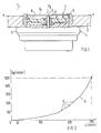
- the switching characteristic curve 9, as shown, for example, in the diagram in FIG. 2, is adapted to the minimum pleasure pressure suitable for the respective speed. If the pressure in the tire is too low for the speed traveled, a warning is triggered via the pressure switch 1.
- the switching point of the pressure sensor can thus be changed in accordance with the speed of the motor vehicle along the characteristic curve 9, so that only a single pressure switch 1 is required for different tire air pressures, which are controlled via the additional mass 7a; 7b; 7c; 7d of the switching membrane 7 can be reproduced.
- the desired switching characteristics are included with a corresponding increase in mass on the switching membrane to achieve corresponding pressure differences between the pressure at low and high speeds.
Landscapes
- Engineering & Computer Science (AREA)
- Mechanical Engineering (AREA)
- Measuring Fluid Pressure (AREA)
Abstract
Ein Druckschalter zur Überwachung eines Reifenluftdrucks, insbesondere für Kraftfahrzeugreifen ist an einer Radfelge befestigt und wird vom Luftdruck im Reifen betätigt. Er umfaßt eine Referenzdruckkammer, die zum Reifen hin durch eine elektrisch leitende Schaltmembran abgeschlossen ist und einen mit dieser Membran zusammenwirkenden Kontaktstift trägt. Die Schaltmembran weist eine derart fliehkraftabhängig gesteuerte Masse auf, daß der Schaltpunkt des Druckschalters selbsttätig veränderbar ist. 
Description
Die Erfindung bezieht sich auf einen Druckschalter nach dem Oberbegriff des Anspruchs 1.The invention relates to a pressure switch according to the preamble of claim 1.
Es ist aus der DE-OS 35 43 864 ein Reifendrucksensor zur Überwachung eines Reifenluftdrucks bekannt, der einen Druckschalter mit einer Referenzdruckkammer umfaßt, die zum Reifeninnenraum hin durch eine elektrisch leitende Schaltmembran abgeschlossen ist und einen mit dieser Membran zusammenwirkenden Kontaktstift trägt. Bei Kontakt des Stiftes mit der Schaltmembran herrscht im Fahrzeugreifen ein vorgeschriebener Betriebsdruck. Ein derartiger Druckschalter ist über einen Geschwindigkeitsbereich von z.B. 0 - 280 km/h nur für einen Schaltpunkt auslegbar, das heißt, daß über einen einzigen Druckschalter nur ein Luftdruck entweder bei hohen oder bei niederen Geschwindigkeiten genau zu überwachen ist.It is known from DE-OS 35 43 864 a tire pressure sensor for monitoring a tire air pressure, which comprises a pressure switch with a reference pressure chamber, which is closed to the tire interior by an electrically conductive switching membrane and carries a contact pin cooperating with this membrane. When the pin comes into contact with the switching membrane, there is a prescribed operating pressure in the vehicle tire. Such a pressure switch can be operated over a speed range of e.g. 0 - 280 km / h can only be designed for one switching point, which means that only a single pressure switch can be used to precisely monitor air pressure either at high or at low speeds.
Aufgabe der Erfindung ist es, einen Druckschalter nach der im Oberbegriff des Anspruchs 1 genannten Gattung zu schaffen, mit dem Mindestluftdrücke eines Fahrzeugrades in Abhängigkeit von der Fahrzeuggeschwindigkeit zu überwachen sind.The object of the invention is to provide a pressure switch according to the type mentioned in the preamble of claim 1, with which the minimum air pressures of a vehicle wheel are to be monitored as a function of the vehicle speed.
Diese Aufgabe wird erfindungsgemäß durch die kennzeichnenden Merkmale des Anspruchs 1 gelöst. Weitere vorteilhafte Merkmale beinhalten die Unteransprüche.This object is achieved by the characterizing features of claim 1. The dependent claims contain further advantageous features.
Die mit der Erfindung hauptsächlich erzielten Vorteile bestehen darin, daß durch die besondere Ausbildung der Schaltmembran der Schaltpunkt des Druckschalters dem zur jeweiligen Geschwindigkeit notwendigen Mindestluftdruck anpaßbar ist. Dies wird durch eine definierte Wanddicke bzw. durch eine Massenanhäufung an der Schaltmembran erzielt, wodurch sich eine vergrößerte Flächenmasse und eine sich hieraus über die Fahrzeuggeschwindigkeit erhöhende Fliehkraft ergibt, die eine entsprechende Auslenkbewegung der Schaltmembrane bewirkt, wodurch sich ein selbsttätig veränderbarer Schaltpunkt in Abhängigkeit von der Geschwindigkeit einstellt.The main advantages achieved by the invention are that the switching membrane of the pressure switch can be adapted to the minimum air pressure required for the respective speed by the special design of the switching membrane. This is achieved by a defined wall thickness or by a mass accumulation on the switching membrane, which results in an increased mass per unit area and a result of this Centrifugal force increases vehicle speed, which causes a corresponding deflection movement of the switching membrane, whereby an automatically variable switching point is set as a function of the speed.
Ausführungsbeispiele der Erfindung sind in der Zeichnung dargestellt und werden im folgenden näher beschrieben.Embodiments of the invention are shown in the drawing and are described in more detail below.
Es zeigen:
- Fig. 1 einen Druckschalter teilweise im Schnitt,
- Fig. 2 ein beispielweises Diagramm über den Fliehkrafteinfluß auf die Schaltmembrane und den Druckschalter,
- Fig. 3 eine Darstellung der Schaltmembran mit einer punktförmigen Massenanhäufung,
- Fig. 4 eine Draufsicht auf eine Schaltmembran mit am Umfang verteilt angeordneten Massenanhäufungen und
- Fig. 5 eine Schaltmembran im Schnitt mit einer innen angeordneten Hülse als Masse.
- 1 is a pressure switch partially in section,
- 2 shows an exemplary diagram of the influence of centrifugal force on the switching diaphragm and the pressure switch,
- 3 is an illustration of the switching membrane with a point-like mass accumulation,
- Fig. 4 is a plan view of a switching membrane with mass accumulations and arranged distributed around the circumference
- Fig. 5 is a switching membrane in section with an inner sleeve as a mass.
Ein Druckschalter 1 ist in einer Radfelge 2 angeordnet und umfaßt in einem Sensorgehäuse 5 eine Druckkammer 6 mit einem Referenzdruck Pi, die zum Luftdruck PR im Reifen durch eine Schaltmembran 7 abgeschlossen ist. In der Mitte der Druckkammer 6 ist ein Kontaktstift 8 druckdicht und elektrisch isoliert in der Referenzdruckkammer 6 befestigt. Die Schaltmembran 7 und der Kontaktstift 8 sind so zueinander angeordnet, daß bei einem ausreichenden Luftdruck PR im Fahrzeugreifen zwischen ihnen eine elektrische Verbindung besteht. Fällt dagegen der Luftdruck PR im Reifen unter den Referenzdruck Pi in der Druckkammer 6 ab, so hebt die Schaltmembran 7 vom Kontaktstift 8 ab und es wird eine Warnanzeige durch eine nicht näher dargestellte elektrische Schaltung oder dergleichen ausgelöst.A pressure switch 1 is arranged in a
Die Membran 7 bildet ein Element, das den Schaltpunkt S des Druckschalters 1 entsprechend der Geschwindigkeit selbsttätig nachbildet. Hierzu ist die Membran 7 mit einer zusätzlichen Masse behaftet oder mit einer gegenüber der bekannten Schaltmembrane (DE-OS 35 43 864) z.B. stärkeren Wanddicke d versehen, wie Fig. 1 näher zeigt. Hierdurch wird ein Fliehkrafteinfluß auf die Membran 7 verstärkt. Insbesondere weist die Schaltmembran 7 eine durchgehend gleiche Wanddicke d (Position 7a) auf. Denkbar wäre aber auch eine ungleichmäßige Wanddicke bzw. eine Massenanhäufung 7b im zentrischen Bereich der Membrane 7. Diese Massenanhäufung 7b kann aus einer punktförmigen Masse oder aus einer Hülse 7d bestehen, die innenseitig der Membrane 7 angeordnet ist und den Schaltstift 8 mit Freiraum umgibt. Desgleichen kann eine Massenanhäufung 7c gleichmäßig über den Umfang der Membran 7 verteilt angeordnet sein. Insbesondere ist die Membran 7 in einer annähernd rechtwinklig zur Kraftrichtung F der Fliehkraft verlaufenden senkrechten Querebene Y-Y angeordnet.The
Wie aus dem Diagramm gemäß Fig. 2, welches die Nachführung des Schaltpunktes in Abhängigkeit von der Fahrgeschwindigkeit zeigt, zu erkennen ist, kann der Schaltpunkt S des Druckschalters 1 entsprechend dem für den Reifen bei der jeweiligen Geschwindigkeit notwendigen Luftdruck angepaßt werden. Das heißt, der notwendige Luftdruck des Reifens für die jeweilige Geschwindigkeit des Reifens kann überwacht werden, so daß im unteren Geschwindigkeitsbereich Z.B. bis 160 km/h ein um ca. 0,5 bar niederer Luftdruck gefahren werden kann als bei Vmax = 280 km/h. Die Schaltkennlinie 9, wie beispielsweise im Diagramm in Fig. 2 dargestellt, wird dem zur jeweiligen Geschwindigkeit passenden Mindestlustdruck angepaßt. Falls der Druck im Reifen zu nieder für die gefahrene Geschwindigkeit ist, wird über den Druckschalter 1 eine Warnung ausgelöst.As can be seen from the diagram according to FIG. 2, which shows the adjustment of the switching point as a function of the driving speed, the switching point S of the pressure switch 1 can be adapted in accordance with the air pressure required for the tire at the respective speed. This means that the tire air pressure required for the respective speed of the tire can be monitored, so that in the lower speed range, for example, up to 160 km / h, an air pressure which is approximately 0.5 bar lower than at V max = 280 km / H. The switching characteristic curve 9, as shown, for example, in the diagram in FIG. 2, is adapted to the minimum pleasure pressure suitable for the respective speed. If the pressure in the tire is too low for the speed traveled, a warning is triggered via the pressure switch 1.
Der Schaltpunkt des Drucksensors ist somit entsprechend der gefahrenen Geschwindigkeit des Kraftfahrzeugs entlang der Kennlinie 9 veränderbar, so daß nur ein einziger Druckschalter 1 für verschiedene Reifenluftdrücke erforderlich ist, die über die fliehkraftabhängig gesteuerte zusätzliche Masse 7a; 7b; 7c; 7d der Schaltmembran 7 nachbildbar sind.The switching point of the pressure sensor can thus be changed in accordance with the speed of the motor vehicle along the characteristic curve 9, so that only a single pressure switch 1 is required for different tire air pressures, which are controlled via the
Für andere Anwendungsfälle bzw. Fahrzeuge sind in Abhängigkeit von Reifenbauart, Reifendimension, Radlast, Felgendimension, Schaltereinbaulage (Radios und und Winkellage), Membrandurchmesser, Membransteifigkeit usw. durch eine entsprechende Massenerhöhung an der Schaltmembran die gewünschten Schaltkennlinien (Pschalt = f(V)) mit entsprechenden Druckunterschieden zwischen dem Druck bei niederen und hohen Geschwindigkeiten zu erreichen.For other applications or vehicles, depending on the type of tire, tire dimension, wheel load, rim dimension, switch installation position (radios and and angular position), membrane diameter, membrane stiffness, etc., the desired switching characteristics (Pschalt = f (V)) are included with a corresponding increase in mass on the switching membrane to achieve corresponding pressure differences between the pressure at low and high speeds.
Claims (7)
Applications Claiming Priority (2)
| Application Number | Priority Date | Filing Date | Title |
|---|---|---|---|
| DE3810763A DE3810763A1 (en) | 1988-03-30 | 1988-03-30 | PRESSURE SWITCH FOR MONITORING A TIRE AIR PRESSURE, IN PARTICULAR OF MOTOR VEHICLE TIRES |
| DE3810763 | 1988-03-30 |
Publications (2)
| Publication Number | Publication Date |
|---|---|
| EP0335082A2 true EP0335082A2 (en) | 1989-10-04 |
| EP0335082A3 EP0335082A3 (en) | 1990-03-21 |
Family
ID=6351037
Family Applications (1)
| Application Number | Title | Priority Date | Filing Date |
|---|---|---|---|
| EP89101965A Withdrawn EP0335082A3 (en) | 1988-03-30 | 1989-02-04 | Pressure sensor for monitoring tyre pressure, particularly vehicle tyre pressure |
Country Status (4)
| Country | Link |
|---|---|
| US (1) | US4894639A (en) |
| EP (1) | EP0335082A3 (en) |
| JP (1) | JPH01293209A (en) |
| DE (1) | DE3810763A1 (en) |
Cited By (1)
| Publication number | Priority date | Publication date | Assignee | Title |
|---|---|---|---|---|
| WO1994007705A1 (en) * | 1992-10-06 | 1994-04-14 | Hughes Aircraft Company | Vehicle wheel incorporating tire air pressure sensor |
Families Citing this family (14)
| Publication number | Priority date | Publication date | Assignee | Title |
|---|---|---|---|---|
| DE3813846A1 (en) * | 1988-04-23 | 1989-11-02 | Bosch Gmbh Robert | TIRE PRESSURE SENSOR FOR MOTOR VEHICLES |
| JPH0481309A (en) * | 1990-07-24 | 1992-03-16 | Nippondenso Co Ltd | Inflation pressure detecting device |
| US5717135A (en) * | 1991-09-30 | 1998-02-10 | Carl A. Fiorletta | Tire pressure monitoring system utilizing a pressure activated transducer and sensor |
| US5289160A (en) * | 1991-09-30 | 1994-02-22 | Fiorletta Carl A | Tire pressure monitoring system |
| US5487273A (en) * | 1993-09-13 | 1996-01-30 | Alliedsignal Inc. | Turbocharger having pneumatic actuator with pilot valve |
| US5731754A (en) * | 1994-06-03 | 1998-03-24 | Computer Methods Corporation | Transponder and sensor apparatus for sensing and transmitting vehicle tire parameter data |
| US5764137A (en) * | 1996-12-09 | 1998-06-09 | Chrysler Corporation | System and method for diagnosing loss of pressure in tires of a vehicle |
| US7161476B2 (en) | 2000-07-26 | 2007-01-09 | Bridgestone Firestone North American Tire, Llc | Electronic tire management system |
| US8266465B2 (en) | 2000-07-26 | 2012-09-11 | Bridgestone Americas Tire Operation, LLC | System for conserving battery life in a battery operated device |
| US6840086B2 (en) * | 2003-03-06 | 2005-01-11 | Cincinnati Test Systems, Inc. | Method and apparatus for detecting leaks |
| US7051578B2 (en) * | 2003-03-06 | 2006-05-30 | Cincinnati Test Systems, Inc. | Method and apparatus for detecting a gas |
| US7178385B2 (en) * | 2004-06-18 | 2007-02-20 | Cincinnati Test Systems, Inc. | Method and apparatus for detecting leaks |
| DE102007035647A1 (en) * | 2007-07-27 | 2009-01-29 | Claas Selbstfahrende Erntemaschinen Gmbh | Agricultural working machine |
| CN109050172A (en) * | 2018-09-27 | 2018-12-21 | 山东华宇工学院 | A kind of automobile flat tire emergency system |
Family Cites Families (5)
| Publication number | Priority date | Publication date | Assignee | Title |
|---|---|---|---|---|
| US3760350A (en) * | 1972-03-27 | 1973-09-18 | E Johnson | Pneumatic tire pressure sensor |
| US4229728A (en) * | 1978-12-20 | 1980-10-21 | Eaton Corporation | Tire pressure monitor |
| DE3543864A1 (en) * | 1985-12-12 | 1987-06-19 | Bosch Gmbh Robert | TIRE PRESSURE SENSOR FOR MOTOR VEHICLES |
| DE3723511A1 (en) * | 1987-07-16 | 1989-01-26 | Bosch Gmbh Robert | Tyre pressure switch for motor vehicles |
| DE3741129A1 (en) * | 1987-12-04 | 1989-06-15 | Bosch Gmbh Robert | TIRE PRESSURE SENSOR FOR MOTOR VEHICLES |
-
1988
- 1988-03-30 DE DE3810763A patent/DE3810763A1/en not_active Withdrawn
-
1989
- 1989-02-04 EP EP89101965A patent/EP0335082A3/en not_active Withdrawn
- 1989-03-24 US US07/328,541 patent/US4894639A/en not_active Expired - Fee Related
- 1989-03-30 JP JP1076879A patent/JPH01293209A/en active Pending
Cited By (1)
| Publication number | Priority date | Publication date | Assignee | Title |
|---|---|---|---|---|
| WO1994007705A1 (en) * | 1992-10-06 | 1994-04-14 | Hughes Aircraft Company | Vehicle wheel incorporating tire air pressure sensor |
Also Published As
| Publication number | Publication date |
|---|---|
| US4894639A (en) | 1990-01-16 |
| DE3810763A1 (en) | 1989-10-12 |
| JPH01293209A (en) | 1989-11-27 |
| EP0335082A3 (en) | 1990-03-21 |
Similar Documents
| Publication | Publication Date | Title |
|---|---|---|
| EP0335082A2 (en) | Pressure sensor for monitoring tyre pressure, particularly vehicle tyre pressure | |
| DE2630511C2 (en) | Tire pressure control system | |
| EP0371966B1 (en) | Tyre pressure sensor for motor vehicles | |
| DE1605706C3 (en) | Warning device to indicate that the air pressure in pneumatic tires is too low | |
| DE19856860A1 (en) | Method for operating a device for monitoring and wireless signaling of a pressure change in pneumatic tires on vehicles | |
| DE3108247A1 (en) | TIRE PRESSURE CONTROL SYSTEM | |
| DE19745195C2 (en) | Level control device for vehicles with air springs | |
| EP0391922A1 (en) | TIRE PRESSURE SENSOR FOR MOTOR VEHICLES. | |
| EP0155346B1 (en) | Vehicle tyre pressure-regulating device | |
| EP0166123A2 (en) | Compressed-air supply device for a tyre-pressure regulating system | |
| DE2736603C3 (en) | Tire pressure control system | |
| DE3300457C2 (en) | ||
| EP0157205B1 (en) | Air pressure monitoring arrangement for vehicle tyres | |
| DE3124481A1 (en) | Tyre pressure control system | |
| DE3105037A1 (en) | Tyre pressure control system | |
| DE1505123A1 (en) | Device for remote monitoring of tire pressure in motor vehicles | |
| DE3803138C2 (en) | Device for controlling a windshield wiper of vehicles, in particular motor vehicles | |
| EP0303829B1 (en) | Warning device for a tyred vehicle wheel | |
| DE2854772A1 (en) | Pressure monitor for motor vehicle tyres - has separate monitor on each valve linked to central warning circuit | |
| DE2925181A1 (en) | Contact bar for vehicle parking collision prevention - has deformable fluid container or electromechanical transducers connected to e.g. dashboard indicator | |
| DE894509C (en) | Device for displaying the negative pressure in pneumatic vehicle tires | |
| DE2533891A1 (en) | ANOMALY DETECTOR FOR TIRE PRESSURE | |
| DE494376C (en) | Electric display device for the escape of air from pneumatic tires of motor vehicles | |
| DE2116058A1 (en) | Level control device, in particular for air suspension systems for vehicles | |
| DE2854518A1 (en) | Low tyre pressure indicator - has membrane-operated indicator contacts on sensing valve with hollow spindle screwed into wheel rim |
Legal Events
| Date | Code | Title | Description |
|---|---|---|---|
| PUAI | Public reference made under article 153(3) epc to a published international application that has entered the european phase |
Free format text: ORIGINAL CODE: 0009012 |
|
| AK | Designated contracting states |
Kind code of ref document: A2 Designated state(s): DE ES FR GB IT NL SE |
|
| PUAL | Search report despatched |
Free format text: ORIGINAL CODE: 0009013 |
|
| AK | Designated contracting states |
Kind code of ref document: A3 Designated state(s): DE ES FR GB IT NL SE |
|
| 17P | Request for examination filed |
Effective date: 19900725 |
|
| 17Q | First examination report despatched |
Effective date: 19910215 |
|
| STAA | Information on the status of an ep patent application or granted ep patent |
Free format text: STATUS: THE APPLICATION HAS BEEN WITHDRAWN |
|
| 18W | Application withdrawn |
Withdrawal date: 19910526 |
|
| R18W | Application withdrawn (corrected) |
Effective date: 19910526 |