EP0334681A1 - Stimulateur cardiaque avec régulation automatique de sortie perfectionnée - Google Patents
Stimulateur cardiaque avec régulation automatique de sortie perfectionnée Download PDFInfo
- Publication number
- EP0334681A1 EP0334681A1 EP89303019A EP89303019A EP0334681A1 EP 0334681 A1 EP0334681 A1 EP 0334681A1 EP 89303019 A EP89303019 A EP 89303019A EP 89303019 A EP89303019 A EP 89303019A EP 0334681 A1 EP0334681 A1 EP 0334681A1
- Authority
- EP
- European Patent Office
- Prior art keywords
- rate
- pacing
- pulse
- generation
- capture
- Prior art date
- Legal status (The legal status is an assumption and is not a legal conclusion. Google has not performed a legal analysis and makes no representation as to the accuracy of the status listed.)
- Granted
Links
Images


Classifications
-
- A—HUMAN NECESSITIES
- A61—MEDICAL OR VETERINARY SCIENCE; HYGIENE
- A61N—ELECTROTHERAPY; MAGNETOTHERAPY; RADIATION THERAPY; ULTRASOUND THERAPY
- A61N1/00—Electrotherapy; Circuits therefor
- A61N1/18—Applying electric currents by contact electrodes
- A61N1/32—Applying electric currents by contact electrodes alternating or intermittent currents
- A61N1/36—Applying electric currents by contact electrodes alternating or intermittent currents for stimulation
- A61N1/362—Heart stimulators
- A61N1/365—Heart stimulators controlled by a physiological parameter, e.g. heart potential
- A61N1/36507—Heart stimulators controlled by a physiological parameter, e.g. heart potential controlled by gradient or slope of the heart potential
-
- A—HUMAN NECESSITIES
- A61—MEDICAL OR VETERINARY SCIENCE; HYGIENE
- A61N—ELECTROTHERAPY; MAGNETOTHERAPY; RADIATION THERAPY; ULTRASOUND THERAPY
- A61N1/00—Electrotherapy; Circuits therefor
- A61N1/18—Applying electric currents by contact electrodes
- A61N1/32—Applying electric currents by contact electrodes alternating or intermittent currents
- A61N1/36—Applying electric currents by contact electrodes alternating or intermittent currents for stimulation
- A61N1/362—Heart stimulators
- A61N1/37—Monitoring; Protecting
- A61N1/3706—Pacemaker parameters
-
- A—HUMAN NECESSITIES
- A61—MEDICAL OR VETERINARY SCIENCE; HYGIENE
- A61N—ELECTROTHERAPY; MAGNETOTHERAPY; RADIATION THERAPY; ULTRASOUND THERAPY
- A61N1/00—Electrotherapy; Circuits therefor
- A61N1/18—Applying electric currents by contact electrodes
- A61N1/32—Applying electric currents by contact electrodes alternating or intermittent currents
- A61N1/36—Applying electric currents by contact electrodes alternating or intermittent currents for stimulation
- A61N1/362—Heart stimulators
- A61N1/37—Monitoring; Protecting
- A61N1/371—Capture, i.e. successful stimulation
- A61N1/3712—Auto-capture, i.e. automatic adjustment of the stimulation threshold
Definitions
- This invention relates to pacemakers, and more particularly to pacemakers with automatic output regulation.
- Automatic output regulation in a pacemaker, a type of self-adaptation, involves testing for the lowest possible pulse output energy which results in heart capture, a concept not unknown in pacing but one which has not achieved high grades for successful implementation. What often confounds an automatic output regulation circuit is a fusion beat.
- a fusion beat is a combined intrinsic and paced event; the pacemaker does not have enough time between start of the intrinsic beat and timeout of the escape interval to inhibit generation of a stimulus.
- a fusion beat is difficult to sense and can lead to an erroneous determination that there has been a loss of capture and that there is therefore a need to increase the output pulse energy.
- the pacing rate is increased slightly to avoid fusion beats if that is really the problem.
- a back-up pulse (of high energy) is generated shortly after the failure to sense an evoked response from the preceding ordinary stimulus. If the back-up pulse fails to evoke a response, it is an indication that the preceding stimulus resulted in a fusion beat. Only if the back-up pulse gives rise to an evoked potential is it made clear that the preceding stimulus resulted in a heart capture failure and that the output pulse energy may have to be increased.
- a rate-responsive pacemaker In order to satisfy the metabolic needs of a patient, it is advantageous to implant a rate-responsive pacemaker. Such a device responds to some rate control parameter (RCP) whcih is indicative of the body's need for cardiac output.
- RCP rate control parameter
- the measured value of the rate control parameter (“MRCP”) is used to adjust the pacing rate.
- RCP rate control parameter
- MRCP rate control parameter
- a rate-responsive pacemaker One of the most daunting problems in designing a rate-responsive pacemaker is to devise an algorithm which relates the MRCP to pacing rate -- even assuming that the MRCP is measured correctly. It would be highly advantageous to provide a closed-loop control system for a rate-responsive pacemaker. Such a negative feedback system would allow the control of pacing rate automatically. Instead of having to derive or look up in a table the value of pacing rate which is to be set for each MRCP, a closed-loop control system would simply change the rate in the direction which tends to keep the MRCP constant. If the MRCP tends to change in either direction, the rate adjusts in a direction which returns the MRCP to its value before the change.
- the depolarization gradient an excellent rate-control parameter is that increased stress (including both emotional stress and exercise) causes the depolarization gradient to decrease while an increased heart rate causes the depolarization gradient to increase . It is the opposite effects which stress and heart rate have on the depolarization gradient that permits a closed-loop control system to be effected.
- An increase in stress causes the MRCP to decrease. In the case of increased stress, what is desired is an increased rate.
- the pacemaker is made to respond to a decrease in MRCP by increasing its rate. But when the rate increases, so does the MRCP; the MRCP increase is in a direction which is opposite to the original MRCP decrease.
- the pacing rate stops increasing.
- the governing rule is that when there is a change in MRCP, the rate is changed so that MRCP moves in the opposite direction, until MRCP is restored. This is a negative feedback system, and it avoids the need for complex relationship between a measurement value and the way in which the pacing rate should change.
- an MRCP increases due to the patient having taken a drug, and no change has otherwise taken place in his metabolic needs, it is not desirable for the pacing rate to change in such a way that the MRCP will be returned to its previous value.
- the operation of a mechanical or chemical sensor may change with time. Even when measuring the depolarization gradient and using it as a rate-control parameter, if for one reason or another the lead shifts in position it is possible for a shift to appear in the MRCP. In such a case, without some way to compensate for a non -stress change in MRCP, a closed-loop control system would effect a permanent shift in pacing rate.
- the Wirtzfeld et al closed-loop control system did not provide compensation for this type of shift in the rate-control parameter; as far as we know, the Wirtzfeld et al pacemaker has not been commercialized. It is anything but a simple matter to compensate for drifts in a rate-control parameter which are unrelated to stress.
- the pacing rate is not changed in a direction which tends to keep MRCP constant. Instead, the pacing rate is adjusted in accordance with a parameter denominated as (MRCP-target), where target is a value indicative of changes in MRCP due to non-stress and non-rate factors (such as changes which result from lead maturation, drugs, etc.).
- MRCP-target a parameter denominated as (MRCP-target)
- target is a value indicative of changes in MRCP due to non-stress and non-rate factors (such as changes which result from lead maturation, drugs, etc.).
- the depolarization gradient is the integral of the QRS waveform of an evoked potential. Not every QRS waveform must be processed, but QRS waveforms must be integrated often enough to allow MRCP up-dating to follow metabolic changes. Since it is evoked potentials which are measured in the illustrative embodiment of the invention, this means that periodically stimulated beats must take place, as opposed to intrinsic beats. Some way must be found to pace the heart periodically even if pacing pulses are not otherwise required. This is accomplished by increasing the pacing rate on an individual beat basis to just above the intrinsic rate when an MRCP sample is required.
- the heart is paced in an illustrative embodiment of the inventin approximately every fourth beat in order that an MRCP sample be taken, it is especially important to use the lowest possible energy in each pulse in order to extend battery life and to minimize distortion of MRCP due to lead polarization. It is therefore particularly important to provide improved automatic output regulation.
- the single-chamber cardiac pacing system 10 of FIG. 1 includes a pulse generator 12 which is of generally conventional design except as otherwise described herein.
- Bipolar lead 14 also is of conventional design.
- tip electrode 16 may be a porous, platinum-iridium, hemispherically-shaped electrode on the distal end of lead 14.
- Ring electrode 18 is typically spaced at least 0.5 cm from tip electrode 16.
- the circuitry of pulse generator 12 is sealed in a hermetic container, for example, titanium can 20, as shown.
- a hermetic container for example, titanium can 20, as shown.
- the pacer can 20 is treated as an independent electrode, the single-chamber cardiac pacing system 10 carries three electrodes: can 20, tip electrode 16 and ring electrode 18.
- the operation of the pacing system as described can apply to the ventricular lead of a dual-chamber cardiac pacer. However, for purposes of simplicity of disclosure, the details of operation will be disclosed for only a ventricular pacer.
- a pacing cycle begins when an electrical stimulus is emitted from tip electrode 16 to stimulate muscular contraction of at least a portion of the heart.
- the stimulus is of a magnitude and width which is not harmful to the heart and which is well known to those skilled in the art to evoke a contraction response from the heart muscle.
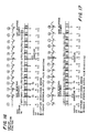
- the pulse of electric stimulus 30 is graphed in FIG. 2 as signal A, having a typical duration of 0.1 to 2 milliseconds.
- pacer can 20 serving as a reference electrode for electrodes 16 and 18.
- Stimulus 30 is transmitted via conductor 22 to tip electrode 16.
- the naturally occurring cardiac electrical activity is amplified by sense amplifier 44 and transmitted via line 31 to a spontaneous event and noise detector 46 to begin a timing process.
- the signal is extended via conductor 26 into timing and control circuitry module 50 which, in turn, has feedback and control lines 28, 29 connected, respectively, to detector 46 and to evoked response detector 54.
- an output for timing and control circuit 50 is connected via line 35 to output and charge dump circuit 48.
- spontaneous event and noise detector 46 extends a corresponding control signal on conductor 27 to the timing and control circuit 50.
- charge dump circuit 48 Immediately following the emission of pulse 30 from electrode 16, charge dump circuit 48 is activated, with the charge dump pulse 34 being illustrated as signal B of FIG. 2, the duration of the charge dump being about 5 to 15 milliseconds.
- the charge dump may be provided using a conventional charge dump circuit 48 such as illustrated in FIG. 4.
- the electrical charge on output coupling capacitor 60 (FIG. 4) and tip electrode 16 are discharged through the heart 21.
- the post-stimulus polarization potential of electrode 16 is quickly diminished.
- Evoked response detector 54 is then activated by timing and control circuit 50 over conductor 29.
- a window of time 36 is opened as illustrated by signal C of FIG. 2, its magnitude being typically 60 milliseconds. It is only during this time that evoked response detector 54 is activated to detect an evoked electrical response from the heart.
- the stimulus from electrode 16 can be seen to be in the unipolar mode.
- detection of the evoked response is unipolar, being detected by ring electrode 18, which communicates over conductor 72 and through amplifier 52 to detector 54.
- Detector 54 transmits the detected signal via line 55 to integration circuit 57.
- the integrated signal which is discussed in detail below, is transmitted to timing and control circuit 50 via line 59.
- the window of time 36 shown as signal C in FIG. 2 is positioned in a block of time 32 (signal D of FIG. 2) which generally represents a refractory period.
- the evoked response can be detected during a refractory period 32.
- Signal E in FIG. 2 shows the evoked cardiac electrical activity 38 within evoked response detection period 36, and which is detected by ring electrode 18.
- the evoked heartbeat response 38 is detected by ring electrode 18 in the unipolar mode.
- the detected evoked response is fed via line 55 to integration circuit 57, and the output of the integration circuit is extended via line 59 to timing and control circuit 50.
- an alert period 40 (signal F; FIG. 2) is provided to monitor naturally occuring cardiac electrical activity until such time as the next pulse 30 is applied to tip electrode 16.
- Detector circuitry 46 may be activated and shut down by timing and control circuit 50 via line 28.
- both electrodes 16 and 18 operate together in a bipolar configuration, with both electrodes communicating with amplifier 44, which in turn is connected to spontaneous event detector 46. (If desired, intrinsic beats can be sensed using a unipolar configuration.)
- a signal may be sent from spontaneous event detector 46 via line 26 to timing and control circuit 50, to cause the electronics to recycle from any time in the cycle to the beginning of the cycle, without generation of an electric pulse 30 from tip electrode 16. Every time natural cardiac electrical activity takes place during alert period 40, no stimulus will be generated.
- timing and control circuit 50 will cause another pulse to be generated via electrode 16.
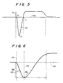
- typical cardiograph tracing of the changing potential in the ventricle of a heart is shown throughout most of a single cardiac cycle with respect to a reference base line of predetermined voltage, typically zero volts.
- the Q-point represents the beginning of the R-wave 152 where the voltage trace crosses or is closest to the base line 154, prior to forming R-wave 152.
- the R-point is the peak of R-wave 152, irrespective of whether the trace is shown in its form of FIG. 5 or in inverted form, which is possible with other recording systems.
- the S-point is where the trace crosses base line 154.
- the evoked potential is detected on ring electrode 18.
- the signal is transmitted via heart amplifier 52 and detector 54 to integration circuit 57 via line 55.
- the integrated signal 140 is known as the depolarization gradient, and is illustrated in FIG. 6.
- the major parameter of interest to the present invention is the magnitude 162 of the depolarization gradient 140, from the base line 154 to the peak 148.
- the area of R-wave 152 decreases in magnitude. Therefore, the depolarization gradient will similarly decrease in magnitude.
- the depolarization gradient lends itself to detection and analysis. The occurrence of bimodal R waves will not negatively impact upon the value of the depolarization gradient as a stress measuring tool.
- the depolarization gradient is calculated and compared to a target value. If the depolarization gradient is equal to the target value, there is no change in the heart pacing stimulus rate. The escape interval remains the same. If the depolarization gradient is smaller than the target value, a determination is made as to whether or not the stimulus rate is at its programmed maximum rate. If it is at its maximum rate, the stimulus rate is not increased. However, if the stimulus rate is less than the programmed maximum rate, the rate is incremented by some predetermined value. Should the depolarization gradient increase, indicating a reduction in stress, the determination is made as to whether or not the rate of stimulation is as its minimum programmed rate. If it is at the programmed minimum rate, there is no further decrease in rate. If it is not at its minimum programmed rate, the rate of the stimulation is decreased by some predetermined value.
- Spontaneous electrical events such as those conducted from the atrium to the ventricle via the cardiac conduction pathway or those arising within the ventricle itself (premature ventricular contractions) are detected. These signals are amplified by the amplifier 44 and detected in the spontaneous event and noise detector 46. The timing and control circuit 50 acts upon these events to reset the escape interval. (Further, these spontaneous electrical events may be integrated if desired, and the depolarization gradient may be determined. Rate changes or escape interval changes may be implemented based on the depolarization gradient of the spontaneous electrical events in the same manner that they are implemented based on the depolarization gradient of the evoked potentials. To this end, the integration circuit 57 of FIG. 3 is shown as receiving the signal from spontaneous event and noise detector 46 via line 160, although only evoked potentials are processed in the illustrative embodiment of the invention.)
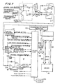
- Timing and control circuit 50 comprises a microcomputer 190 which addresses a memory 192 via address bus 194.
- Data bus 196 is coupled between microcomputer 190 and memory 192, and conventional control logic 198 is coupled to data bus 196.
- a crystal controlled clock 200 is used for providing appropriate clock pulses for the system.
- the functions of the control logic inputs and outputs are designated. The drawing of FIG.
- FIG. 7 also shows a programming/telemetry transceiver 220 for allowing supervisory information and data to be telemetered out for reception by a programmer or other receiving device, and for allowing the pacemaker to be programmed by an external programmer, as is well known in the art.
- a programming/telemetry transceiver 220 for allowing supervisory information and data to be telemetered out for reception by a programmer or other receiving device, and for allowing the pacemaker to be programmed by an external programmer, as is well known in the art.
- Control logic circuit 198 provides a gradient measure enable signal to electronic switch 202 and to analog-to-digital converter 204 which is at the output of an integrating amplifier 206. It can be seen that the amplified potential sensed at ring 18 is applied to the negative input of the integrating amplifier 206 which, when enabled, provides an amplified analog output that is converted to digital data by means of analog-to-digital converter 204.
- the digital data contains the depolarization gradient information, which is provided to the control logic circuit 198 whereby appropriate timing of the stimulation pulses is achieved in response thereto.
- the gradient measure enable signal 210 is illustrativelyed as signal G on FIG. 2. It commences at the same time that the capture detection window 36 commences and the gradient measure enable signal 210 continues for up to 130 milliseconds.
- the several control signals depicted on FIG. 7 are for the most part self-explanatory. For example, it will be apparent that a spontaneous event and noise detector 46 is provided with a programmable reference voltage which serves as a threshold. It is enabled to sense R waves by an alert period window signal.
- the two signals which it provides to the control logic represent the sensing of an intrinsic beat or the presence of noise.
- FIGS. 8, 9 and 10 The reason that the depolarization gradient lends itself to closed-loop control is exemplified by FIGS. 8, 9 and 10.
- the key to the closed-loop control is that the physiological effects of emotional or physical stress cause the RCP to become smaller, whereas increased heart rate causes the RCP to become larger.
- FIGS. 8 and 9 The opposite effects of stress and heart rate on the depolarization gradient are shown in FIGS. 8 and 9, in which the RCP refers to the depolarization gradient.
- the bottom of the first graph shows the patient at rest, then starting to exercise, then exercising more strenuously, and finally returning to rest. This is referred to as the workload.
- the patient's heart is paced at a fixed rate in the case illustrated in FIG. 8, at a rate of 70 pulses per minute.
- the top of the graph shows the RCP, measured in microvolt-seconds, as decreasing with increasing stress.
- FIG. 8 shows how the RCP decreases if the heart rate does not increase when the patient is under stress.
- FIG. 9 shows what happens if the heart rate is increased to the value higher than that required for the current state of stress; in such a case the RCP increases.
- the patient is at rest but the heart rate is arbitrarily increased and then decreased over a period of 5 minutes.
- the RCP is seen to increase with increasing rate.
- FIGS. 8 and 9 show that increased stress and increased heart rate have opposite effects on the RCP.
- the graph of FIG. 10 depicts the rate response of the closed-loop control mechanism of our invention.
- the RCP tends to decrease (FIG. 8); however, any tendency for the RCP to decrease causes the control mechanism to increase the heart rate.
- the increase in heart rate restores the RCP to its pre-change value (FIG. 9).
- the net result of maintaining the value of RCP constant is that the heart rate follows the patient's workload. This is the significance of what is shown in FIG. 10: simply by maintaining the RCP constant, the heart rate can be made to follow the metabolic needs of the patient without any complicated relationship between RCP and heart rate having to be devised.
- the basic rule is that when there is a change in the measured value of the RCP (MRCP), the rate should be increased or decreased in the direction which restores MRCP. But while the basic rule is a simple to state, it is not sufficient to implement a closed-loop control system. The reason is due to changes which occur over long periods of time (long compared to how fast MRCP changes due to stress) because of other factors, e.g., drugs. If a drug causes MRCP to decrease and to remain lower than it otherwise would be, then the pacer will cause the pacing rate to be higher than it should be; the pacer does not know why MRCP decreased and would blindly follow the rule to increase the rate so that MRCP remains constant. Simple control of the type described does not work in the absence of compensation for changes in MRCP due to factors other than those related to stress.
- the solution is to control rate in a feedback network not so that MRCP stays constant, but so that (MRCP-target) stays constant.
- Target is a value which ideally changes with non -stress "inputs”; it changes the same way as those "inputs” affect MRCP.
- Drugs may change MRCP, but if they also change target by the same amount, the control parameter -- (MRCP-target) -- affects rate in accordance with only changes in MRCP due to stress.
- the operative rule is to change rate in a direction which compensates for changes in (MRCP-target), with target remaining constant over the short term and thus allowing the pacer to respond to stress changes.
- (MRCP-target) decreases, for example, it is assumed that it is decreasing because MRCP decreased in response to the patient starting to exercise.
- the MRCP still changes in accordance with stress and rate in opposite directions (which is why the control system works in the first place).
- the MRCP also still changes in accordance with other "inputs", but now the effect of these other inputs on the control loop is cancelled by having target respond to these inputs in the same way that MRCP does, and by using (MRCP-target) as the control parameter.
- the control system is not only closed-loop, but adaptive as well.
- the pacer pace at or near the minimum rate in the absence of exercise, i.e., most of the time the minimum rate is wanted.
- the pacer imposes a very small bias which slowly returns the rate to the minimum by decreasing target; this is done just in case the reduced MRCP which is causing pacing above the minimum rate is really due to drift.
- the bias is so small that the tendency to decrease rate is overpowered by changes in the rate-response system due to stress (increased or decreased rate). Eventually a return is made to minimum rate. The usual reason is that the patient has stopped exercising.
- (MRCP-target) when minimum rate is reached. Pacing is at the minimum rate and is not going any lower. MRCP may have changed due to drift, but the present MRCP is what is now being measured for minimum rate. No more changes in rate are desired (in the absence of stress changes); the rate is where it should be. At the minimum rate, (MRCP-target) should equal zero. The reason is that should stress increase, i.e., the patient start to exercise, it is desired that (MRCP-target) go negative so it can control a rate increase . If target is too small and (MRCP-target) is positive , (MRCP-target) may not go negative when MRCP decreases.
- MRCP would have to decrease appreciably just to get rid of the unnecessary positive residue (introduced by forcing target down during rate-response pacing, and possibly drift).
- MRCP-target when pacing is at the minimum rate (MRCP-target) is made equal to zero by increasing target as much as necessary -- until it equals MRCP.
- MRCP-target When exercise then starts, the slightest decrease in MRCP due to stress will make (MRCP-target) negative, and the rate will start increasing. So Rule 2 is to increase target until it equals MRCP whenever minimum rate is achieved. Moreover, target is increased very rapidly so that the pacemaker will be ready to increase the pacing rate as soon as exercise commences.
- (MRCP-target) When minimum rate is achieved, (MRCP-target) cannot be negative. A negative value for (MRCP-target) causes the rate-response system to control a rate increase, i.e., above minimum rate; thus (MRCP-target) cannot be negative at minimum rate. If (MRCP-target) is zero at minimum rate, there is nothing to do; there is equality between MRCP and target, rate response leaves the rate as is, and it is just where it is desired. In fact, when (MRCP-target) is positive, target is increased precisely so that a difference of zero is obtained. When the pacing rate is above minimum rate due to rate re sponse, on the other hand, target is reduced continuously, albeit slowly. As target is decreased, so is rate. What happens is that eventually (MRCP-target) is positive when minimum rate is obtained -- either because target has been decreased by the built-in bias, or, more commonly, the patient has stopped exercising. It is at this time that target is rapidly increased until it equals MRCP.
- the original question was how to derive a value for target which reflects changes in MRCP which are due to non-stress factors.
- the question has been answered by the two Rules just given.
- the pacer may not know what the non-stress factors have done to MRCP. But it does know that the feedback loop, controlled by (MRCP-target), is controlling pacing at the minimum rate.
- the pacer may be measuring a different value of MRCP than it did yesterday for the same conditions, but whatever the new value, target is just right for it to give the minimum rate for this particular value of MRCP. And once the correct value of target is had for one rate, it can be used for all rates; target stays constant over the short term.
- target When minimum rate is reached, target may be too small [(MRCP-target) is positive] and must be increased because the built-in bias made it too small by continuously reducing it while rate response was operative. Whenever a return is made to minimum rate, as always happens, the pacer adjusts target to correct for what it did to it and also for non-stress inputs which have occurred since the last time a departure was made from minimum rate.
- the decrease in target during rate-response pacing is designed to force a return to minimum rate at which time target can be corrected.
- minimum rate will be achieved because the patient stops exercising at which time target is corrected to compensate for non-stress effects on MRCP. Decreasing target during rate-response pacing to force a return to minimum rate is the pacer's fail-safe mechanism.
- An intrinsic rhythm is really a minimum rate; it is higher than the programmed value, but the intrinsic rate will not permit the pacer to pace more slowly. So it is treated like case 2, with one difference: target is increased as in case 2, but at the programmed calibration speed used for case 1 (not the very fast speed of case 2). This is Rule 3. The reason is that the intrinsic rate may be due to some pathological factor. When target is increased, in effect the pacer is controlled to pace at a higher rate. If target is rapidly increased, as in case 2, all rates would be biased upward just because momentarily there was a pathologically high intrinsic rate. To avoid this, target is increased slowly when the intrinsic rate is higher than the minimum rate (case 3), just as it is slowly decreased in case 1.
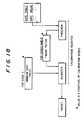
- the calibration register which controls changes in target is shown in FIG. 18.
- the calibration register consists of three registers referred to as the tweeker, the tweek factor and the adjuster.
- the tweeker and the adjuster are 8-bit registers.
- the tweek factor used in cases 1 and 3 described in the preceding section, can have the value of 2, 3 or 4. Whenever the tweeker overflows or underflows, the tweek factor is added to or subtracted from the value in the adjuster. Whenever the adjuster overflows or underflows, target is incremented or decremented.
- the tweek factor is a function of the programmed calibration speed, and the speed at which target is changed thus depends on the calibration speed.
- tweeker value should not be changed by the same absolute amount (a decrease in case 1 and an increase in case 3) independent of the pacing rate. It is desired that target change by a fixed percentage per hour, based solely on the calibration speed and independent of the rate. The faster the pacing, however, the more rapidly MRCP samples are taken and thus the faster the increases and decreases are applied to the tweeker value. It is apparent, therefore, that if target is to change by a fixed percentage over any given period of time, the value by which tweeker is changed whenever an MRCP sample is taken must necessarily vary with the rate at which the samples are taken.
- a slow calibration speed is applicable to an active patient who is not taking any drug therapy (or who may be taking drug therapy, but infrequently (once or twice per day)).
- target can change by about 10% per hour when the pacer is operating in cases 1 and 3.
- the medium calibration speed applies to drugs which reach peak serum level over a moderate period of time, i.e., drugs taken every 4-6 hours. This is the default case, and target can change by about 15% per hour.
- a fast calibration speed is applicable to a patient who take drugs which reach peak serum level very quickly, i.e., drugs taken every 2-4 hours. In such a case, target can change by about 20% per hour.
- the pacer measures the RCP every fourth cycle and uses (MRCP-target) to control the pacing rate.
- the RCP is measured only every fourth cycle in order to save power and increase rate stability. If the present RCP is smaller than target, the rate is increased (5 ppm every fourth cycle) until RCP equals target or the programmed maximum rate is obtained. If the present RCP is greater than target, than the rate is decreased (5 ppm every fourth cycle) until it equals target, or until the programmed minimum rate is obtained.
- the RCP is the depolarization gradient of the evoked potential. This means that pacing must occur in order to measure the RCP. If the intrinsic ventricular rate becomes faster than the pacing rate (which pacing rate is established by the RCP measurement), then sensed events will inhibit pacing pulses. (The illustrative embodiment of the invention allows rate response only in the VVI mode.) If there is an intrinsic beat during a cycle in which the RCP is to be measured, the mea surement cannot be taken. In order to take a measurement, the pacer increases its rate by 5 ppm every fourth cycle until the intrinsic rate is exceeded and an output pulse is issued. (Although the rate is increased only every fourth cycle in order that there not be too abrupt a change, an attempt is made to measure the RCP during every cycle, rather than just every fourth cycle, in the case of overdrive.)
- an MRCP value is taken and the pacing rate is adjusted accordingly.
- the adjustment which is made is based on the rate which was in effect prior to the last 5 ppm increase that resulted in a pacer output, i.e., when the pacer rate was within 5 ppm below the intrinsic rate.
- the next pacing pulse will be 60 milliseconds closer to the next P wave than it otherwise would be because the preceding pacing pulse was this much closer to the preceding P wave.
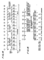
- rate response is enabled can be programmed by the physician. Two timing cycles with rate response on are illustrated in FIGS. 14 and 15. (Throughout the timing cycle drawings, the darkened area of each cycle depicts the usual refractory period.) The former is a case where overdrive is not necessary. The latter is a case in which intrinsic activity affects the RCP measurement.
- the pacer increases its rate by 5 ppm; the escape interval thus decreases by about 57 milliseconds between the second and third cycles. The pacer maintains the rate at this level until the RCP is measured again four cycles later.
- the pacer increases its rate once again by 5 ppm, with the escape interval decreasing to 750 milliseconds between the sixth and seventh cycles.
- the RCP measurement in the tenth cycle indicates that the rate is still not high enough; MRCP is still smaller than target, and the pacer increases its rate once again by 5 ppm with the escape interval dropping to 706 milliseconds.
- the need to decrease the rate is reflected in the next RCP measurement at the beginning of the fourteenth cycle.
- the measured RCP is now found to be larger than target.
- the pacer decreases its rate by 5 ppm, and the escape interval rises to 750 milliseconds between the fourteenth and fifteenth cycles.
- Fig. 15 The effect of sensing intrinsic activity during rate response is illustrated in Fig. 15.
- the patient's sinus rate is 71 beats per minute, faster than the initial pacing rate of 70 pulses per minute.
- an RCP measurement is due, but it cannot be made because the sensed intrinsic activity inhibits the generation of an ouput pulse.
- the pacing rate increases by 5 ppm between the third and fourth cycles. With the pacing rate increasing from 70 to 75 ppm, the pacing rate is now faster than the intrinsic rate and an output pulse is generated at the start of the fourth cycle.
- An RCP measurement is now made and it is found that the measured value of RCP is equal to target.
- the pacing rate is decreased by 10 ppm, and it is then increased by 5 ppm in the next cycle.
- the V-R interval between beats four and five in FIG. 15 is shown as 890 milliseconds, corresponding to a rate of 67 ppm.
- the R-R interval during the next cycle is 845 milliseconds, corresponding to an intrinsic rate of 71 ppm.
- the pacing rate is maintained at 70 ppm, within 5 ppm of the intrinsic rate.
- the next RCP measurement which is due in the seventh cycle (four cycles after the initial RCP measurement attempt was made, not four cycles after success was achieved), cannot be taken because intrinsic activity is sensed once again.
- the pacing rate is again increased by 5 ppm between the seventh and eighth beats to allow an RCP measurement to be taken.
- the amplitude and width of each output current pulse are preferably such that minimal energy is expended.
- a threshold search is conducted periodically to determine the pacing threshold.
- the output values are automatically adjusted accordingly, and a predetermined safety margin is added.
- Automatic output regulation can be programmed on or off, but when it is programmed on a threshold search is automatically initiated every 54,000 ventricular events; at an average rate of 75 ppm, a threshold search is initiated every twelve hours. Exactly how often the search takes place depends on the pacing rate.
- a threshold search also occurs upon request by a programmer.
- Another aspect of automatic output regulation is capture verification which occurs every four cycles. If loss of capture is detected, it is followed by an adjustment of the output and a verification of capture on a beat-by-beat basis until capture is regained and a predetermined safety margin is added. During every cycle in which loss of capture is detected, a 10-milliampere, 1-millisecond back-up output pulse is issued. Capture verification can result only in an increase of output energy. A decrease can occur only during a threshold search.
- the starting pulse width a programmed parameter, is one of five possible values.
- Each output incremental step includes both a current amplitude and a pulse width. For example, with a starting pulse width of 0.4 milliseconds, the lowest energy output pulse has an amplitude of 1 milliampere and a pulse width of 0.4 milliseconds. For any starting pulse width, the incremental steps follow first a vertical and then a horizontal line. Thus in the case under consideration, the starting pulse width remains the same but the current amplitude increases up to 5 milliamperes. Thereafter, the current amplitude remains at 5 milliamperes while the pulse width increases in 0.1-millisecond steps up to the maximum of 1.0 milliseconds.
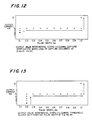
- FIG. 12 What is shown in FIG. 12 is an illustration of how the pacer changes the output pulse in order to regain capture when loss of capture is detected at an output setting of 3 milliamperes and 0.1 milliseconds.
- the pulse width is first maintained constant until the output current amplitude is increased to 5 milliamperes. Then the current amplitude remains constant as the pulse width is increased.
- the output values are increased by two steps in order to provide a safety margin.
- the pacer automatically initiates Stat Set pacing at 10 mA/1.0 ms.
- FIG. 11 Another sequence is illustrated in FIG. 11, this one representing a threshold search with a starting pulse width of 0.2 ms.
- the initial current amplitude is always 1 mA.
- the first four incremental steps involve increasing the current amplitude while maintaining the pulse width at the programmed starting value. Thereafter, it is the pulse width which is incremented.
- the pacer automatically initiates Stat Set pacing at 10 mA/1.0 ms.
- Capture verification occurs every fourth cycle (when intrinsic beats are not in control). Thus when automatic output regulation is programmed on, loss of capture cannot occur for more than three consecutive cycles without a back-up pulse being issued. If rate response is also programmed on, capture verification occurs in conjunction with the RCP measurements, during every fourth cycle.
- the pacer performs capture verification during each succeeding cycle, not every fourth cycle, until capture is regained and the new output values have been determined.
- the pacer verifies cardiac capture through detection of an evoked response following the generation of a pacing pulse. Loss of capture is defined by an evoked response not being detected within 60 milliseconds following an output pulse.
- the pacer issues a back-up pulse (10 mA/1.0 ms) 60 milliseconds after the initial output pulse; a primary purpose of the back-up pulse is to insure that there is a beat.
- the loss of capture results in rate response being suspended; also, the present pacing rate is increased by 5 ppm in order to eliminate possible fusion beats. (Fusion beats make capture verification very difficult.)
- the back-up output pulse is again issued 60 milliseconds after the ordinary pacing pulse, and the pacing rate is again increased by 5 ppm.
- the total increase of 10 ppm above the rate in effect when loss of capture was detected is designed to eliminate fusion beats if that is what was occurring.
- rate response is resumed, an RCP measurement is taken, and the rate is adjusted accordingly. But if capture is not detected in either of these two cycles, the output values are increased by one step each cycle until capture is detected. Pacing is maintained at the elevated rate of 10 ppm over the rate in effect when loss of capture was first detected until capture verification is complete.
- the output values are kept constant until capture is verified for three consecutive cycles. Then the pacer issues an ECG "signature" which consists of two output pulses, each at 10 mA/1.0 ms, 60 milliseconds apart. The ECG signature indicates that capture has been regained. The purpose of the signature pulses is to avoid confusion on the part of a person analyzing an ECG trace. Once capture has been verified, the output values are incremented by two steps to establish a safety margin.
- Stat Set pacing is initiated (10 mA/1.0 ms) and automatic output regulation is disabled. Automatic output regulation resumes only if the automatic output regulation is programmed on once again. With Stat Set pacing, rate response is also disabled, if it was programmed on in the first place. The reason for this is that the evoked potential waveform is distorted by large-magnitude Stat Set pacing pulses.
- the new output values are first reflected in the cycle following the ECG signature, and they remain in effect until the threshold search is initiated again or loss of cap ture is again detected for three consectutive cycles. If rate response is programmed on, the pacer resumes rate response once the new output values are determined. If rate response has been programmed off, the pacer returns to the programmed minimum rate in the cycle following the ECG signature cycle.
- the rate cannot exceed the programmed maximum rate, if rate response is programmed on. If rate response if programmed off, the rate cannot exceed 100 ppm, or 15 ppm plus the programmed minimum rate, whichever is greater. (This is the definition of maximum rate in this case.) Whenever the rate has been increased to its maximum allowable level, capture verification continues but rate increases are not allowed.
- the capture verification function is illustrated in FIG. 16.
- an evoked response is not detected during the 60-millisecond capture verification window which follows the initial output pulse. This causes a back-up output pulse (10 mA/1.0 ms) to be issued 60 milliseconds after the ordinary pacing pulse.
- the refractory interval is reinitiated.
- the rate is increased by 5 ppm, with the escape interval thus decreasing from 857 milliseconds to 800 milliseconds. If rate response was programmed on, it is suspended as soon as loss of capture is detected.
- the ordinary output pulse again fails to obtain capture.
- a back-up pulse is issued, the refractory interval is re-initiated, and the rate is again increased by 5 ppm.
- failure to obtain capture is detected for the third consecutive time.
- the output values which initially are 4 mA and 0.2 ms, are increased one step to 5 mA/0.2 ms (see table of FIG. 11, row 2, column 4).
- the increase in output results in capture by the ordinary output pulse.
- the present output values of 5 mA/0.2 ms continue to achieve capture in the next two cycles. Because capture is verified for three consecutive cycles (cycles 5, 6 and 7), an ECG signature is issued in the eighth cycle, two output pulses, each at 10 mA/1.0 ms, 60 milliseconds apart.
- the establishment of a safety margin is reflected in the ninth cycle.
- the safety margin is an increase in output by two steps, in this case from 5 mA/0.2 ms to 5 mA/0.4 ms. Capture verification at the new output values continues in cycles 9, 10 and 11. In the twelfth cycle, rate response is resumed, the RCP is measured, and the pacer adjusts its rate accordingly. Thereafter, RCP measurements and capture verification occur every fourth cycle.
- a threshold search is initiated to determine the pacing threshold and to automatically set the output parameter values accordingly. (This includes the usual safety margin of two steps.) After the initial determination, the threshold search is performed automatically approximately every twelve hours, and whenever it is initiated by the programmer.
- the ECG signature is issued.
- the pacer increases its present rate by 5 ppm, suspends rate response, lowers the output current to 1 mA, and sets the pulse width to the selected programmed starting value.
- the current is lowered to 1 mA because the object of the threshold search is to use the lowest possible current amplitude. If capture is not obtained at the lowest output settings, a back-up output pulse is issued 60 milliseconds after the initial output pulse.
- the pacing rate is again increased by 5 ppm and the output current is increased to 2 mA. If capture is not obtained at these output settings, a back-up pulse is issued and the output current is increased by 1 mA (up to a maximum of 5 mA) each cycle until capture is obtained.
- the pacing rate is maintained at the elevated level (10 ppm above the rate in effect when the threshold search was initiated) until the threshold search is completed. If capture cannot be obtained at 5mA and the starting pulse width value, the pacer increases the pulse width by 0.1 ms (up to a maximum of 1.0 ms) every cycle until capture is obtained. Back-up pulses continue to be issued in each cycle in which capture is not obtained. It will be apparent that the threshold search sequence is very similar to the capture verification sequence, with the major difference being that the capture verification sequence begins with the present output values of current amplitude and pulse width, whereas the threshold search always begins with the lowest possible current amplitude and the programmed starting pulse width.
- the new output values are first reflected in the cycle following the ECG signature and remain in effect until the next threshold search in initiated or loss of capture is detected for three consecutive cycles.
- the pacer resumes rate response, measures the RCP, and adjusts its rate accordingly in the fourth cycle following the ECG signature cycle. If rate response has been programmed off, the pacer returns to the programmed minimum rate in the cycle following the ECG signature cycle.
- the search is temporarily suspended and the pacer increases its rate by 5 ppm each cycle until a pacer output pulse is issued.
- the reason for this is that a threshold search cannot possibly be conducted in the absence of pacing pulses. Once pacing starts to take place, the threshold search is continued at the rate in effect when pacing pulses started to be issued.
- rate response While the rate is being increased automatically in this manner, it is not allowed to exceed the programmed maximum rate, if rate response is on. If rate response if off, the rate is not allowed to exceed 100 ppm, or 15 ppm plus the programmed minimum rate, whichever is greater. If the rate is increased to its maximum allowable level, the threshold search will continue as long as pacing is in effect, but further rate increases are not allowed. If there are 25 cycles of intrinsic beats or noise beyond the allowable threshold, the threshold search is canceled, rate response is resumed (or the pacer returns to the programmed minumum rate if rate response is off), and the output returns to the values that were in effect when the search was initiated.
- the threshold search function is illustrated in FIG. 17.
- the ECG signature of two output pulses at 10 mA/1.0 ms, issued 60 milliseconds apart, indicates the initiation of a threshold search.
- the present pacing rate is increased by 5 ppm and rate response is suspended, assuming that it was programmed on in the first place.
- an output pulse is issued at the lowest output current value, 1 mA, and the selected starting pulse width value, in this case an assumed value of 0.2 ms.
- This output pulse fails to obtain capture and a back-up output pulse of 10 mA/1.0 ms is issued 60 milliseconds after the initial output pulse.
- the refractory interval is re-initiated, the rate is increased by 5 ppm, and the output values are increased by one step, from 1 mA/0.2 ms to 2 mA/o.2 ms.
- the output pulse issued at 2 mA/0.2 ms also fails to obtain capture and a back-up output pulse is issued 60 milliseconds after the initial output pulse.
- the rate remains at the elevated level of 10 ppm above the rate which was in effect when the search was started, and the output values are increased by one step.
- the new output pulse, issued in the fifth cycle, is shown as succeeded in obtaining capture.
- the output values are maintained at the 3 mA/0.2 ms setting until capture is verified for three consectutive cycles, the fifth, sixth and seventh. Then an ECG signature is issued in the eighth cycle to indicate the end of the threshold search.
- the establishment of a safety margin (output values increased by two steps, from 3 mA/0.2 ms to 5 mA/0.2 ms) is reflected in the ninth cycle. In the twelfth cycle, rate response is resumed, the RCP is measured, and the pacer rate is adjusted accordingly. Thereafter, RCP measurements and capture verification occur every fourth cycle.
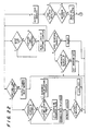
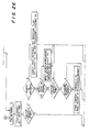
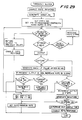
- FIGS. 19-28 The flow chart of FIGS. 19-28 is very detailed and will be described below. At this point it will be useful to consider the flow chart of FIG. 29, however, for two reasons. First, it represents the threshold search which has just been described and accordingly a consideration of the flow chart at this time will help in the understanding of the threshold search. The second reason for considering the flow chart of FIG. 29 is to gain an appreciation of the difference in levels of flow charts such as that of FIG. 29 and that of FIGS. 19-28.
- the flow chart of FIG. 29 includes a step such as "capture verified three times?". The actual programming of a pacer may entail repetition of the same basic loop over and over again, with different steps being executed each time depending on what transpired during the preceding loops.
- rate response is first disabled.
- the ECG signature is then generated, and the starting output values for a pacing pulse are set (1 mA and programmed starting pulse width).
- the rate is increased by 5 ppm to give precedence to paced events over intrinsic events.
- a test is then made to determine whether there have been 25 beats of noise or intrinsic activity during the search. If the answer is in the affirmative, the threshold search is aborted. The output values (amplitude and pulse width) are returned to the previous values. If rate response is off, rate returns to the minimum rate. Rate response is then enabled if it has been programmed on, and an exit is made from the routine.
- rate response is programmed off, the rate cannot exceed 100 ppm, or 15 ppm above the minimum rate, whichever is greater.] If it is not, the rate is increased 5 ppm in an attempt to control pacing so that the threshold search can be conducted. If the rate is already at the maximum rate, however, the rate is not increased. This process continues until the rate is high enough to allow an output to be generated. The pacer then checks whether that pulse captures the heart.
- a back-up pulse is gener ated after 60 milliseconds to insure that the patient is supported. It will be recalled that the rate is increased by a total of 10 ppm at the start of the threshold search in order to minimize the incidence of fusion beats. If the present output has an amplitude of 1 milliampere, it is an indication that the first pulse in the search has been generated. The rate is increased by another 5 ppm, for a total of 10. During the next pass through the loop, the output amplitude will not be 1 milliampere, and another rate increase will not take place.
- the next step must take place in the pulse width. If the pulse width is less than 0.8 milliseconds, the pulse width is increased by 0.1 milliseconds, and a return is made to the top of the loop.
- the pulse width is 0.8 milliseconds, however, it is assumed that capture cannot be obtained at less than the maximum pulse energy. Accordingly, the amplitude is set at 10 milliamperes and the pulse width is set at 1 millisecond. In such a case, Stat Set pacing takes place so the rate is set to 70 ppm (the new minimum rate), and the loop is exited. It should be noted that rate response is not enabled since rate response measurements are not considered valid when the pacing pulses have maximum energy.
- capture was not obtained. If capture is detected, the next test is to see whether capture has not only been verified this time through the loop, but whether it has been verified for a total of three times. Capture is verified three times to insure that a reliable threshold has been determined and to reduce the possibility of fusion beats causing a false indication of capture threshold. If the answer is in the negative, a return is made to the top of the loop without the output being increased in energy. The output will be increased one again only if capture is not verified during a cycle before three successive captures take place.
- the threshold has been determined.
- the output is incremented by two steps as a safety margin, and the signature is generated.
- a test is now made to see whether rate response has been programmed on. If it has not, the rate is set to the minimum rate and the loop is exited. Otherwise, rate response is enabled before exiting the threshold search.
- the depolarization gradient is processed twice during each cycle when it is examined. First, it is checked 60 milliseconds after the generation of an output pulse to see whether there has been capture, i.e., whether the depolarization gradient has a sufficient amplitude to indicate capture. But this is not the amplitude which is used as the MRCP.
- the MRCP is the maximum amplitude depicted in FIG. 6.
- the MRCP sample is taken somewhere between 70 and 130 milliseconds following the generation of an output pulse.
- the depolarization gradient is measured every 2 milliseconds, starting with 70 milliseconds subsequent to the generation of an output pulse.
- the peak value is obtained 90 milliseconds following the generation of the output pulse.
- the depolarization gradient is examined only twice -- 60 milliseconds after the generation of the output pulse to see if the magnitude is sufficient to represent an evoked response, and 90 milliseconds after the generation of the output pulse when the maximum value is expected.
- the value at 90 milliseconds is not used to determine whether there has been an evoked response because it is desired to generate a back-up pulse, if one is needed, no later than 60 milliseconds after the generation of an output pulse.
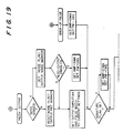
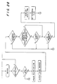
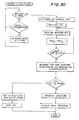
- the high-level flow chart of FIG. 30 depicts a target initialization procedure.
- the detailed steps required for the initialization process are not shown in the low-level flow chart of FIGS. 19-28.
- the reason for this is that once it is understood how the high-level steps such as those involved in the threshold search of FIG. 29 can be implemented in a low-level detailed flow chart such as that of FIGS. 19-28, it will be apparent to those skilled in the art how to similarly implement the steps in the high-level initialization flow chart.
- a value of target is first determined by the initialization process, a process which is automatically activated when rate response is programmed on. (Target initialization also occurs when a new minimum rate, output current or pulse width is programmed, on when automatic output regulation is programmed on or off while rate response is on.) It is thereafter that the pacer continuously makes adjustments to the value of target in accordance with the three rules which comprise the target-adjustment algorithm.
- the initialization process is shown in FIG. 30.
- the initial value of target should be determined while the patient is at rest, i.e., when the RCP is not being effected by emotional or physical stress. If initialization is performed while the patient is under emotional or physical stress, the target RCP will be established at too low a level and may not allow an appropriate rate response. However, the effect is only temporary because the automatic calibration function eventually adjusts target to the appropriate minimum-rate level. For that matter, target will eventually be adjusted correctly even in the absence of an initialization process.
- the RCP is measured for a number of paced cycles in order to establish a value for target. If intrinsic activity is sensed during the initialization process, initialization is temporarily suspended and the rate is increased by 5 ppm every cycle until pacing resumes.
- the first test which is made is to see whether intrinsic R waves are being sensed. As indicated at the top of the flow chart, if an intrinsic beat takes place, the rate is increased by 5 ppm unless the rate is already at the maximum. (Maximum rate in the flow chart of FIG. 30 has the same meaning as maximum rate in the flow chart of FIG. 29.) Only if a paced beat takes place does the system move on to determine the RCP sample time as indicated in the flow chart.
- the actual determination of the RCP sample time is the same as that discussed above in connection with the flow chart of FIG. 29.
- the depolarization gradient is examined every 2 milliseconds until it is determined when following an output pulse a maximum value is obtained. Thereafter, that is the RCP sample time.
- the RCP sample time is determined, although it is indicated as only one step in each of FIGS. 29 and 30. Successive RCP sample times are determined until two successive measured values are close enough together for it to be assumed that a sufficient level of accuracy has been achieved. The most recent of the two values is taken as the RCP sample time.
- At least four cycles are required to determine the RCP sample time and to determine an initial value of RCP.
- RCP measurements are taken. It should be noted that to speed up the initialization process, samples are taken every cycle, not every fourth cycle. Furthermore, target is calibrated at an accelerated speed. The calibration speed is that applicable to Rule 2, rather than that applicable to Rules 1 and 3.
- Any measurement system necessarily has a range outside of which values are not considered to be accurate. If during the derivation of target the measured RCP is not out of range, a double pulse signature is generated, and rate response is enabled.
- a status flag is set to indicate this condition.
- the status flag allows the RCP out-of-range condition to be telemetered out to a programmer.
- Stat Set pacing takes place, as indicated at the bottom of FIG. 30. Rate response is not enabled (nor is automatic output regulation).
- the pacer output module heading block shown at the top of FIG. 19 is entered from those parts of the flow chart labeled A, as will be described below.
- the pacer output module is entered when a spontaneous beat has not been sensed and a stimulus is to be issued. It is not certain, however, that there has been no intrinsic beat. It is possible that there was an intrinsic beat, but that it was masked by noise. It is for this reason that the first test which is performed is to determine whether noise was sensed during the preceding cycle.
- a noise flag is set and a noise marker is output by the telemetry circuit.
- Three markers can be output for recording on an ECG trace. The markers represent an output pacing pulse, noise and a sensed event. If it is determined that noise was not sensed during the preceding cycle, then as indicated in FIG. 19 the noise flag is reset. Instead of outputting a noise marker, a pace marker is generated in anticipation of the pacing pulse which is about to be issued.
- the output amplitude and the pulse width are set to whatever settings have been programmed by the physician.
- the current settings -- whether set by the physician in the absence of automatic output regulation, or automatically determined if automatic regulation has been enabled -- are used to generate the pulse.
- the back-up pulse module heading block is entered at such a point in the flow chart, at which time the output amplitude is set at 10 milliamperes and the pulse width is set at 1 millisecond.
- the flow chart proceeds to the top of FIG. 20 at which point blanking is started. This is the conventional step by which the sense amplifier is protected from large pulses. Because the system of the invention also includes an integrator (see FIG. 7) which must be protected, the integra tor is also blanked just prior to generation of the pacing pulse. In the next step the pacing pulse is generated.
- the third step in FIG. 20 is the pulsing of the telemetry coil. This step has nothing to do with the invention itself.
- the telemetry coil is pulsed only to tell the programmer that now is an advantageous time to program, if programming is required, because pulsing has just taken place.
- programming causes an interruption in sensing/pacing, especially if the programming takes longer to complete than the escape interval.
- the interruption time can be minimized by starting the programming at the beginning of an escape interval.
- the blanking timer is set at 140 milliseconds; this is the time during which the sensing of intrinsic beats or noise is not allowed.
- the charge dump timer is set for 10 milliseconds; this is the time during which the charge which is stored in body tissues is dissipated (see top left of FIG. 7).
- the microprocessor is put to "sleep" whenever possible in order to minimize power dissipation.
- the microprocessor is awakened by the timing out of a timer or, when appropriate, upon the sensing of an event. In the present case, the microprocessor is put to sleep and remains in this state until the first of the two timers times out.
- evoked response measurement is made every fourth beat, or every beat during initialization and threshold searches. Similarly, evoked response measurements are made when there is a loss of capture, or when there is a fusion beat which might be interpreted as a loss of capture.
- the signature consists of two large-amplitude pulses separated by 60 milliseconds. If the signature flag has been set, one such pulse has already been generated in the second step of FIG. 20. In order to generate the second pulse, the capture timer is set, and the second pulse is generated upon its timeout. It is for this reason that the capture timer is set on what would appear to be either of two disconnected needs -- the need to sense an evoked response, or the need for a signature pulse. (If it is a second signature pulse which is required, the RCP sample timer is still set along with the capture timer. Since a measured RCP is not accurate in the presence of a large-amplitude stimulus, the RCP sample timer timeout is ignored, as will become apparent below.)
- the capture sample time is 60 milliseconds. However, by the time the capture sample timer is set, 10 milliseconds have already gone by since the generation of the pacing pulse, as a result of the operation of the charge dump timer. Consequently, the capture sample timer is actually set to 50 milliseconds in order to time out a 60-millisecond capture sample interval. In a similar manner, the RCP sample timer is set to 10 milliseconds less than the RCP sample time which is determined during the initialization routine.
- an RCP sample alone would suffice; it could not only provide an MRCP value, but it could also serve to verify whether there has been an evoked response. However, if there has not been an evoked response it is desired to issue a back-up pulse to support the patient. Since the RCP sample is taken 70-130 milliseconds after the generation of a stimulus, in the event of a fusion beat, perhaps resulting in an MRCP value too low to be recognized as an evoked response, a back-up pulse issued 70-130 milliseconds after the stimulus might actually fall in the T wave, something which is generally to be avoided.
- the integrator (FIG. 7) is turned on so that the depolarization gradient will be measured and values will be available on either timer timeout.
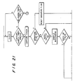
- the system then goes to sleep, as indicated at the top of FIG. 21 until one of the timers times out.
- the system checks whether the capture sample timer has timed out. If not, a check is made whether the blanking timer has timed out. In the event neither timer times out, a pass is made through the loop at the top of FIG. 21 once again. Eventually, one of the timers times out. (Although the capture sample timer has a shorter interval than the blanking timer, the former is usually not set, e.g., on 3 out of 4 cycles, and it is the blanking timer which usually times out.) If it is the capture sample timer which times out, the system moves on to the capture check routine; otherwise, the system moves on to the end blanking routine at the top of FIG. 26. It should be noted that if there is a capture sample timer timeout at the top of FIG. 21, the blanking timer is not ignored. The blanking timer timeout is handled in the end blanking module at the top FIG. 26.
- the capture sample timer is set not only if an evoked response measurement is necessary, but also if a signature pulse pair is required (see bottom of FIG. 20).
- the first pulse of the pair is controlled by the test of the signature flag at the bottom of FIG. 19, followed by the generation of a pacing pulse at the top of FIG. 20.
- the second pulse is controlled by checking the signature flag once again in the middle of FIG. 21.
- the capture sample timer times out 60 milliseconds after the first pulse of the pair is generated, another pacing pulse is generated.
- a pace marker is outputted because another pacing pulse, the second half of the signature, will be issued.
- the pacing rate is increased in two steps of 5 ppm each.
- the purpose of the increase is to minimize the possibility of fusion beats.
- the first increase takes place when the second signature pulse is issued. There are other times when the rate must be increased, but the only one of concern now is when the second signature pulse is to be issued at the start of a threshold search routine.
- the way in which the two pulses of the signature pair are generated illustrates the basic difference between the high-level flow chart of FIG. 29 and the detailed flow chart of FIGS. 19-28.
- FIG. 29 At the top of FIG. 29 there is a single step in which the pulse pair of the signature is said to be generated. In actuality, it takes two passes through the main processing loop because both pulses are generated in the second step of FIG. 20.
- the methodology is easier to understand from a high-level flow chart such as that of FIG. 29, although details of implementation must be left to a low-level flow chart.
- the signature flag set test will be answered in the negative; this point in the main processing loop is usually reached with timeout of the capture sample timer 60 milliseconds after the generation of a non-signature pacing pulse (and usually only on every fourth cycle).
- a test is then made to see whether automatic output regulation has been programmed on. If it has not, a branch is taken to the middle of FIG. 22 where a test is performed to see whether rate response is enabled. If automatic output regulation is on, on the other hand, a check is now made to see whether there has been an evoked response; this is accomplished by sampling the output of the integrator which represents whether or not there has been capture.
- a branch is taken depending upon whether what has been issued is a back-up pulse.
- the pacing pulse can be part of the signature, a back-up pulse or an ordinary stimulus.
- a back-up pulse is generated only when the ordinary stimulus has not captured the heart.
- the next test which is performed, at the top of FIG. 22, is to see whether the noise flag has been set. This flag is set at the top of FIG. 19 if noise has been sensed. If noise is present, a test is not made to see whether the capture limit has been exceeded, i.e., whether the stimulus has captured the heart. The reason for this is that the noise may mask what is really going on.
- the capture-limit-exceeded test in FIG. 22 is performed. If the capture limit is exceeded, the loss of capture counter is reset; it will become apparent below that the current count is of no important because capture has been regained. But if the capture limit has not been exceeded, what is required is a back-up pulse since the pacing stimulus has failed to capture the heart. A pace marker is first outputted. The reason for this is that a back-up pacing pulse will be issued momentarily. The system then checks to see whether it is time for a rate increase. The reason for the test here requires careful understanding.
- the sense signal may be on the decrease by the time 60 milliseconds have elapsed after the output pulse is generated, when the pacer looks to see whether there has been capture; that is because depolarization started early -- even before the stimulus.
- the sense signal for an intrinsic beat is generally narrower than that for a paced beat, so it may be even more difficult to sense capture. Fusion beats may thus be interpreted as a loss of capture.
- the capture-limit-exceeded test as answered in the negative does not necessarily mean that the output parameters of the pacing pulse are not sufficient to capture the heart. It is possible that a fusion beat took place, with the result that the capture sample was too low in magnitude to represent capture. Before the system increases the output pulse energy in an attempt to regain capture, it tries to avoid fusion beats in the hope that it will be possible to verify that the present output pulse energy is sufficient. It is for this reason that the pacing rate is increased twice in succession, 5 ppm each time. A back-up pulse is about to be issued since capture may have been lost and the heart may not have beat, but the rate increase is in preparation for the next ordinary stimulus which will be generated. As shown in FIG. 22, the rate is increased by 5 ppm only if the rate is not already at the maximum. A branch is then taken to point B on FIG. 19 at which time a back-up pulse is generated.
- the auto-output-on test is answered affirmatively because the only time that back-up pulses are generated in the first place is when automatic output regulation has been programmed on.
- the back-up pulse test is answered affirmatively, and a branch is taken to the top of the left path on FIG. 22.
- a test is performed whether it is time for an evoked response measurement.
- a capture sample is taken on all succeeding cycles until the problem is resolved.
- an ordinary stimulus results in a pass through the path on the right side of FIG. 22, the rate is increased by 5 ppm and then a back-up pulse is issued. Following the back-up pulse, a pass is made through the left branch on FIG. 22. Then another ordinary stimulus is generated, a pass is made through the right branch (assuming that the capture-limit-exceeded test is failed once again), the rate is increased by another 5 ppm, a second back-up pulse is generated, and a second pass is taken through the left path on FIG. 22.
- the two 5-ppm increases are designed to eliminate fusion beats if that is the problem. It might be expected that two rate increases in the space of three cycles, would solve the fusion beat problem. We have discovered, however, that the heart can actually exhibit three successive fusion beats, with a 5-bpm rate increase between the first and second, and another 5-bpm increase between the second and third. Each pass through the right path of FIG. 22 can represent a true loss of capture, or it can represent a fusion beat. Increasing the pacing rate even by 10 ppm is not enough to distinguish between the two conditions. It is for this reason that the steps in the left path of FIG. 22 are provided.
- the left path of FIG. 22 is entered following the taking of a capture sample 60 milliseconds after the generation only of a back-up pulse.
- a test is made to see whether the capture limit has been exceeded, i.e., whether the back-up pulse captured the heart. The results of the test are used in a unique way to tell whether what is going on is a true loss of capture or a sequence of fusion beats. Interestingly, capture by a back-up pulse is an indication that what is involved is a loss of capture. This paradox will now be explained.
- Each back-up pulse is generated 60 milliseconds after an ordinary stimulus.
- the question to be answered is whether what appears to have been a loss of capture was really a loss of capture or simply a fusion beat (with the result being that the capture sample was too low in magnitude, as explained above, for the sample to verify capture). If the back-up pulse does not capture the heart now, i.e., the test at the top left of FIG. 22 is answered in the negative, a logical explanation is that capture was not just achieved because the heart tissue is refractory. This in turn means that the heart beat before the back-up pulse was generated. Since an intrinsic beat was not sensed and capture was not verified following generation of the ordinary stimulus, what must have happened is that there was a fusion beat.
- a fusion beat marker is output.
- the system then moves on to FIG. 23 where the RCP sample timer is stopped. Because large-magnitude back-up pulses cause the depolarization gradient to be distorted, RCP samples are not taken following the generation of back-up pulses.
- the microprocessor is then put to sleep and a branch is taken to point C on FIG. 26; the blanking timer was set prior to the generation of the back-up pulse, and the system waits for blanking to end. It should be noted that the rate was increased by at least 5 ppm and by at most 10 ppm by the time the capture-limit-exceeded test at the upper left of FIG. 22 is answered in the negative. The rate is returned as will be described shortly.
- the RCP sample timer is then stopped; the left branch of FIG. 22 is entered because a back-up pulse was generated, and RCP samples are not taken following the generation of back-up pulses.
- the microprocessor is then put to sleep and processing resumes with the end blanking routine when the blanking timer times out.
- threshold-search-in-progress test on FIG. 22 was answered affirmatively. If a threshold search is not in progress, what it means is that an ordinary stimulus resulted in a loss of capture, as confirmed by a back-up pulse now capturing the heart. A test is made to see whether a loss of capture has occurred three times; this is accomplished by examining the loss of capture counter. (The reason for resetting the loss of capture counter in the step shown in the middle of FIG.
- rate response has been enabled.
- the rate may have been increased by 5 ppm or 10 ppm as a result of the effort to avoid fusion beats. This increase should be compensated for.
- rate response has been enabled, there is no need to do anything because the rate will be adjusted by the rate response routine to be described below; the artificial increase in rate will be lowered because the rate is too fast for present physiological needs.
- the microprocessor is put to sleep and the rate response module is entered. When the RCP sample timer times out 70-130 milliseconds after the last stimulus was generated, rate response processing takes place.
- rate response has not been enabled, an adjustment must be made for the 5-ppm or 10-ppm increase in rate which may have taken place.
- a test is made to see whether a threshold search is in progress. At the end of the threshold search, as will be described below, the search-in-progress flag is reset. If it is reset and the answer to the threshold-search-in-progress test is in the negative, the minimum rate is set (it being recalled that the assumption is that rate response has not been enabled). On the other hand, if a threshold search is in progress, the minimum rate is not set, and the system waits for blanking to end.
- the top (right branch) of FIG. 23 is reached when an RCP sample is to be taken as a result of rate response being enabled and a stimulus having been generated. It is at this point that the rate is adjusted in accordance with the measured value of the RCP, and target is adjusted in accordance with the three Rules enumerated above.
- the control parameter (MRCP-target) is zero, and this means that the present rate is on target.
- MRCP does not equal target, a test is performed to see whether the control parameter is positive or negative. A branch is taken to increase the rate by 5 ppm or to decrease it by the same amount.
- a test is performed to see if the rate, after any decrease or increase which may have occurred, is equal to the minimum rate. If it is, a branch is taken to the left side of FIG. 23. If the rate is not equal to the minimum rate, two tests are performed to verify that the rate, as it may have been just adjusted, is within the minimum and maximum limits. If the rate is now below the minimum rate, it is increased; if the rate is now above the maximum rate, it is now decreased. After such an increase or decrease, the processing continues at the bottom of FIG. 23, along the left branch if a minimum rate condition has been obtained, or along the right branch if the rate is between the minimum and maximum limits.
- Rule 2 requires that target be increased rapidly. What is required is that target be successively increased until the difference between it and MRCP is less than some minimum limit (which for all intents and purposes means that target and MRCP are equal). The difference between the target and MRCP is compared to the RCP limit, and a test is then performed to see if the limit is exceeded. If it is not, target has been sufficiently increased and a branch is taken to the bottom of FIG. 25 where the microprocessor is put to sleep and the system waits for the end of blanking. (It is to be recalled that all of this processing is taking place following the generation of a pacing pulse.)
- target adjuster is increased.
- the value stored in the minimum rate tweek register is added to the adjuster register.
- the value stored in the minimum rate tweek register depends on the calibration speed, and it is 16 times larger than the tweek factor. This is not to say that Rule 2 results in the increase of target at a rate which is only 16 times faster than the rate at which target is increased or decreased in Cases 1 and 3. That is because the only time that the tweek factor is added to or subtracted from the adjuster register is when there is an overflow or underflow from the tweeker register. Thus target is increased in Case 2 much faster than just 16 times relative to the speeds in Case 1 and 3.
- the integrator which measures the RCP is provided with two possible gains.
- Target basically follows the RCP measurements, so that one way to decrease target so that it gets back within range is to decrease the gain of the integrator. Therefore, a test is made to see if the integrator is already set to have its low gain value. If it is, nothing can be done to get target back into range.
- the RCP out-of-range flag is set to indicate that rate response is no longer possible, and this information can be telemetered out to the programmer.
- Stat Set pacing (VVI, 70 ppm, 10 mA/1 ms) ensues, and the system awaits for the end of blanking in the usual way.
- the right branch is taken if the newly adjusted rate is somewhere between the minimum and maximum limits.
- the rate is above minimum rate, but it can be due to an intrinsic rhythm having made the pacer increase its rate in order to pace the heart so that an evoked potential could be measured (Case 3), or the rate may be above the minimum rate due to the rate response (Case 1).
- An over drive flag is set when the pacing rate is increased, even though not called for by rate response, in order that a pacing pulse capture the heart so that an evoked potential may be processed.
- the overdrive flag is examined. If it is set, representing Case 3, the overdrive flag is now reset, and the rate is decreased 5 ppm. The overdrive flag is now reset so that another decrease in rate will not occur during a subsequent pass through the loop. The rate is decreased to compensate for the increase (to be described below) which ensured capture. (No matter how many times the rate may have been increased by 5 ppm in order that the pacing rate just exceed the intrinsic rate so that an evoked potential could be processed, only a single decrease of 5 ppm takes place; it is desirable to have the pacing rate just below the intrinsic rate.)
- the microprocessor awakens with timeout of the blanking timer. (Referring to the top of FIG. 21, the timeout may occur at that point in the processing, as previously described. But in either case, an entry is made to the end blanking module on FIG. 26.) Blanking of the sense amplifier now ceases, and the rate timer is set. The rate timer times the escape interval, in accordance with the current rate if it has been adjusted by the rate response processing. If the blanking timer was set by the generation of a back-up pulse, then the escape interval is set not from the generation of the back-up pulse, but rather from 60 milliseconds earlier when the ordinary pacing stimulus was generated. The reason for this is that if the back-up pulse resulted from a fusion beat, the back-up pulse did not accomplish any function, and in order for the next pacing stimulus to capture the heart it should be timed from the fusion beat.
- a test is then performed to see whether it is time for a threshold search. If it is not time, a branch is taken to the middle of FIG. 27 where the microprocessor is put to sleep again, this time waiting for a timeout of the rate timer. As described above, a threshold search is performed approximately once every twelve hours, or upon request by the programmer. If it is time for a threshold search, the first question is whether the search has already been instituted. (An example of a search-in-process is represented by the setting of the search in progress flag on FIG. 22.) If a search is not yet in progress, three steps are executed. First, rate response is disabled because it is not operative during the search.
- the signature flag is set because it is necessary to issue a two-pulse signature so that anyone reviewing an ECG trace will understand what is going on.
- the output is set to 1 milliampere and the programmed starting pulse width, as described above in connection with the description of the threshold search routine depicted on FIG. 29. This is all that happens during the first pass through the steps on FIG. 26.
- the search-in-progress question is answered affirmatively. If there have been 25 beats of noise or sensing since the threshold search began, the search is aborted, and the output is returned to its previous value. But if the search is on-going, the system checks whether capture has been verified three times. The actual incrementing of the output during a threshold search is performed on the left side of FIG. 22. The processing on FIGS. 26 and 27 is concerned more with what happens as a result of the completion of a threshold search or a regain of capture following a loss. In either event, the system checks whether capture has been verified three times in succession.
- capture is verified three times to ensure that a reliable threshold has been determined and to reduce the possibility of fusion beats causing a false indication of capture threshold. If capture has been verified three times, a test is performed to see whether the threshold search in progress is one of the "alternate scheduled." A threshold search is performed approximately every twelve hours. The system records the final threshold value on alternate searches so that it has available one threshold value for approximately each day. The 32 most recent threshold values are stored in a 32-location memory. It is of considerable aid to a physician to known on-going changes in the threshold during the first 30 days or so following implantation of a new lead. (The memory should have a minimum of 7 locations, for storing a week's worth of threshold values -- at least one value per day.) The information is made available by telemetering it out of the pacemaker to a programmer.
- the search-in-progress flag is reset; the search is over.
- the output is also incremented two steps as a safety margin.
- the signature flag is set so that a pulse pair will serve to identify the completion of the threshold search.
- the system determines the RCP sample time as described above, following which rate response is enabled once again if it has been programmed on. Thereafter, the pacemaker stops its processing and waits for the rate timer timeout.
- the rate timer times out, it means that a pacing pulse is required.
- the processing continues at point A on FIG. 19.
- the rate timer if there is no rate timer time-out, it is because an intrinsic beat has been sensed. As shown at the bottom of FIG. 27, the system remains in a loop looking for either a timeout or an intrinsic beat. If it is an intrinsic beat which is the outcome, the "sensed" module on FIG. 28 is entered.
- the first step in this module is to check whether what is believed to have been the sensing of an intrinsic beat fell within the refractory period. If it did, it is not treated as an intrinsic beat, and the loop at the bottom of FIG. 27 is re-entered so that the system can wait for either another sensing or a rate timer timeout. But if the sensed beat was outside the refractory interval, a test is made to see if the system is programmed to operate in the VVT mode. If it is, it means that every sensing is to be followed by a pacing pulse and the processing resumes at the top of FIG. 18. The processing on the right side of FIG. 28 is bypassed; this processing has to do with rate response, and rate response as well as automatic output regulation can be enabled only when the pacer is set to operate in th VVI mode.
- the telemetry coil is pulsed for the same reason that it is on FIG. 20; the best time for programming to commence is immediately after the generation of a pacing pulse (FIG. 20) or immediately after the sensing of an intrinsic beat (FIG. 28), thereby lessening the chance of any interference with pacing functions by the programming.
- a sense marker is then outputted since an intrinsic beat has been sensed.
- the processing on the right side of FIG. 28 pertains to overdriving (increasing the rate above the intrinsic rate) so that an evoked potential may be processed.
- overdrive enabled means that rate response has been programmed on (in which case capture must be had so that an RCP measurement may be made), or -- even if rate response has been programmed off -- a periodic threshold search is being performed. (Even in the absence of rate response, in order to conserve energy the output amplitude and pulse width should not be unnecessarily high.) If overdrive is not enabled, it simply means that there is no reason to ensure that a paced event takes place so that an evoked potential can be measured, and processing continues at the top of FIG. 26 with entry into the end blanking module. Although the blanking timer has not been set and there is no blanking to stop, the processing does continue with setting of the rate timer; since an intrinsic beat has been sensed, the rate timer is set to time from this event.
- the overdrive enabled test is answered in the affirmative, it means that the rate should be increased to the point at which it just exceeds the intrinsic rate so that a placed event can take place in order for an evoked potential to be processed. However, this should happen only when it is appropriate.
- the first test which is now performed is to determine whether a threshold search is in progress (FIG. 29) or target initialization is in progress (FIG. 30). In either case, it is desired that there be a paced event in every cycle and a jump is taken to check whether the pacing rate is al ready at the maximum rate. If it is, there is no way in which it can be increased and a jump is made to the end blanking module on FIG. 26 where the rate timer is set.
- a test is made whether the present cycle is the fourth since the last time that any evoked response measurement was made. If it is not, there is no reason to increase the pacing rate so that a paced event will occur instead of an intrinsic beat, and the end blanking module is entered. On the other hand, if it is the fourth beat and an evoked response is desired, since an intrinsic beat just took place overdrive is necessary. The maximum rate test is performed in this case as well as during a threshold search and target initialization.
- the rate is increased by 5 ppm and the overdrive flag is set. It will be recalled that it is the setting of the overdrive flag which controls the branching at the top of FIG. 24; the state of the flag is an indication whether the current rate, which is above the minimum, is due to overdriving or rate response.
- the rate is increased 5 ppm along which setting of the overdrive flag in order that the net stimulus capture the heart; the rate is decreased 5 ppm immediately following testing of the overdrive flag on FIG. 24 (which point is reached only if there has been a heart capture) when it is determined that the flag is set and that the rate was increased by at least 5 ppm in order to obtain a paced event.
Applications Claiming Priority (2)
| Application Number | Priority Date | Filing Date | Title |
|---|---|---|---|
| US173566 | 1988-03-25 | ||
| US07/173,566 US4878497A (en) | 1988-03-25 | 1988-03-25 | Pacemaker with improved automatic output regulation |
Publications (3)
| Publication Number | Publication Date |
|---|---|
| EP0334681A1 true EP0334681A1 (fr) | 1989-09-27 |
| EP0334681B1 EP0334681B1 (fr) | 1994-11-23 |
| EP0334681B2 EP0334681B2 (fr) | 2004-02-04 |
Family
ID=22632598
Family Applications (1)
| Application Number | Title | Priority Date | Filing Date |
|---|---|---|---|
| EP89303019A Expired - Lifetime EP0334681B2 (fr) | 1988-03-25 | 1989-03-28 | Stimulateur cardiaque avec régulation automatique de sortie perfectionnée |
Country Status (3)
| Country | Link |
|---|---|
| US (1) | US4878497A (fr) |
| EP (1) | EP0334681B2 (fr) |
| DE (1) | DE68919425T3 (fr) |
Cited By (9)
| Publication number | Priority date | Publication date | Assignee | Title |
|---|---|---|---|---|
| EP0453589A1 (fr) * | 1990-04-24 | 1991-10-30 | Pacesetter AB | Dispositif de stimulation des tissus |
| FR2680093A1 (fr) * | 1991-08-09 | 1993-02-12 | Ela Medical Sa | Procede de controle de l'energie de stimulation dans un stimulateur cardiaque. |
| US5330512A (en) * | 1992-12-28 | 1994-07-19 | Cardiac Pacemakers, Inc. | Electrode charge-neutral sensing of evoked ECG |
| EP0681850A2 (fr) * | 1994-05-09 | 1995-11-15 | BIOTRONIK Mess- und Therapiegeräte GmbH & Co Ingenieurbüro Berlin | Procédé pour éviter la coincidence temporelle des activités cardiaques stimulées et spontanées |
| WO1995034343A1 (fr) * | 1994-06-13 | 1995-12-21 | Medtronic, Inc. | Procede et appareil de regulation d'un stimulateur cardiaque lors de la 'capture' automatique |
| EP0719569A2 (fr) * | 1994-12-28 | 1996-07-03 | Pacesetter, Inc. | Détermination du seuil automatique dans un stimulateur cardiaque implantable |
| EP0911063A1 (fr) * | 1997-10-23 | 1999-04-28 | BIOTRONIK Mess- und Therapiegeräte GmbH & Co Ingenieurbüro Berlin | Stimulateur cardiaque à fréquence asservie |
| EP1080744A1 (fr) * | 1999-09-03 | 2001-03-07 | Ela Medical | Stimulateur cardiaque implantable à ajustement automatique du niveau des impulsions de stimulation |
| WO2012087515A3 (fr) * | 2010-12-23 | 2012-10-18 | Cardiac Pacemakers, Inc. | Initialisation du rythme et stimulation cardiaque surmultipliée pour contrôle du seuil de capture |
Families Citing this family (62)
| Publication number | Priority date | Publication date | Assignee | Title |
|---|---|---|---|---|
| EP0334675B2 (fr) * | 1988-03-25 | 2002-03-27 | Telectronics N.V. | Stimulateur cardiaque fonction du rythme avec boucle de réglage fermée |
| DE4013048B4 (de) * | 1990-04-24 | 2004-07-08 | St. Jude Medical Ab | Anordnung zur Gewebestimulation |
| US5233985A (en) * | 1990-08-10 | 1993-08-10 | Medtronic, Inc. | Cardiac pacemaker with operational amplifier output circuit |
| US5265603A (en) * | 1990-12-12 | 1993-11-30 | Medtronic, Inc. | Electronic capture detection for a pacer |
| US5184615A (en) * | 1991-03-08 | 1993-02-09 | Telectronics Pacing Systems, Inc. | Apparatus and method for detecting abnormal cardiac rhythms using evoked potential measurements in an arrhythmia control system |
| US5312446A (en) * | 1992-08-26 | 1994-05-17 | Medtronic, Inc. | Compressed storage of data in cardiac pacemakers |
| US5336244A (en) * | 1992-10-07 | 1994-08-09 | Medtronic, Inc. | Temperature sensor based capture detection for a pacer |
| US5342406A (en) * | 1992-10-07 | 1994-08-30 | Medtronic, Inc. | Oxygen sensor based capture detection for a pacer |
| US5350410A (en) * | 1992-11-23 | 1994-09-27 | Siemens Pacesetter, Inc. | Autocapture system for implantable pulse generator |
| US5443485A (en) * | 1993-09-08 | 1995-08-22 | Intermedics, Inc. | Apparatus and method for capture detection in a cardiac stimulator |
| US5431693A (en) * | 1993-12-10 | 1995-07-11 | Intermedics, Inc. | Method of verifying capture of the heart by a pacemaker |
| US5626620A (en) * | 1995-02-21 | 1997-05-06 | Medtronic, Inc. | Dual chamber pacing system and method with continual adjustment of the AV escape interval so as to maintain optimized ventricular pacing for treating cardiomyopathy |
| SE9501190D0 (sv) * | 1995-03-31 | 1995-03-31 | Pacesetter Ab | Back-up pulse generator |
| US5716383A (en) * | 1996-02-28 | 1998-02-10 | Medtronic, Inc. | Dual chamber pacing system and method with continual adjustment of the AV escape interval so as to maintain optimized ventricular pacing for treating cardiomyopathy |
| US5702427A (en) * | 1996-03-28 | 1997-12-30 | Medtronic, Inc. | Verification of capture using pressure waves transmitted through a pacing lead |
| US5766229A (en) * | 1996-04-15 | 1998-06-16 | Pacesetter, Inc. | Capture verification method and apparatus for implantable pacemaker utilizing heart rhythm stability measurements to minimize the likelihood of fusion |
| US5766230A (en) * | 1996-11-06 | 1998-06-16 | Sulzer Intermedics Inc. | Pacemaker with intra-stimulus capture detection |
| US5861013A (en) * | 1997-04-29 | 1999-01-19 | Medtronic Inc. | Peak tracking capture detection circuit and method |
| US5873898A (en) * | 1997-04-29 | 1999-02-23 | Medtronic, Inc. | Microprocessor capture detection circuit and method |
| US5954756A (en) * | 1998-04-09 | 1999-09-21 | Medtronic, Inc. | Microprocessor capture detection circuit and method |
| EP1147784B1 (fr) | 2000-04-18 | 2004-08-18 | SORIN BIOMEDICA CRM S.r.l. | Un dispositif pour déterminer l'efficacité de la stimulation dans un stimulateur cardiaque |
| US6456881B1 (en) | 2000-08-02 | 2002-09-24 | Pacesetter, Inc. | System and method of identifying fusion for dual-chamber automatic capture stimulation device |
| US7069080B2 (en) | 2000-09-18 | 2006-06-27 | Cameron Health, Inc. | Active housing and subcutaneous electrode cardioversion/defibrillating system |
| US6721597B1 (en) | 2000-09-18 | 2004-04-13 | Cameron Health, Inc. | Subcutaneous only implantable cardioverter defibrillator and optional pacer |
| US6754528B2 (en) | 2001-11-21 | 2004-06-22 | Cameraon Health, Inc. | Apparatus and method of arrhythmia detection in a subcutaneous implantable cardioverter/defibrillator |
| US6952610B2 (en) * | 2000-09-18 | 2005-10-04 | Cameron Health, Inc. | Current waveforms for anti-tachycardia pacing for a subcutaneous implantable cardioverter- defibrillator |
| US7146212B2 (en) | 2000-09-18 | 2006-12-05 | Cameron Health, Inc. | Anti-bradycardia pacing for a subcutaneous implantable cardioverter-defibrillator |
| US7194302B2 (en) | 2000-09-18 | 2007-03-20 | Cameron Health, Inc. | Subcutaneous cardiac stimulator with small contact surface electrodes |
| US6650937B2 (en) * | 2000-11-06 | 2003-11-18 | Medtronic, Inc. | Method and system for gradual cardiac training using an implantable medical device |
| US7526341B2 (en) * | 2002-03-15 | 2009-04-28 | Medtronic, Inc. | Amplitude ramping of waveforms generated by an implantable medical device |
| US7477932B2 (en) | 2003-05-28 | 2009-01-13 | Cardiac Pacemakers, Inc. | Cardiac waveform template creation, maintenance and use |
| WO2005042090A1 (fr) * | 2003-10-27 | 2005-05-12 | St Jude Medical Ab | Dispositif servant a ajuster le degre de sensibilite d'un dispositif medical implantable |
| US20060247693A1 (en) | 2005-04-28 | 2006-11-02 | Yanting Dong | Non-captured intrinsic discrimination in cardiac pacing response classification |
| US7319900B2 (en) | 2003-12-11 | 2008-01-15 | Cardiac Pacemakers, Inc. | Cardiac response classification using multiple classification windows |
| US7774064B2 (en) | 2003-12-12 | 2010-08-10 | Cardiac Pacemakers, Inc. | Cardiac response classification using retriggerable classification windows |
| US8521284B2 (en) | 2003-12-12 | 2013-08-27 | Cardiac Pacemakers, Inc. | Cardiac response classification using multisite sensing and pacing |
| US7706866B2 (en) | 2004-06-24 | 2010-04-27 | Cardiac Pacemakers, Inc. | Automatic orientation determination for ECG measurements using multiple electrodes |
| US7457664B2 (en) * | 2005-05-09 | 2008-11-25 | Cardiac Pacemakers, Inc. | Closed loop cardiac resynchronization therapy using cardiac activation sequence information |
| US7890159B2 (en) | 2004-09-30 | 2011-02-15 | Cardiac Pacemakers, Inc. | Cardiac activation sequence monitoring and tracking |
| US7917196B2 (en) | 2005-05-09 | 2011-03-29 | Cardiac Pacemakers, Inc. | Arrhythmia discrimination using electrocardiograms sensed from multiple implanted electrodes |
| US7805185B2 (en) | 2005-05-09 | 2010-09-28 | Cardiac Pacemakers, In. | Posture monitoring using cardiac activation sequences |
| US7509170B2 (en) | 2005-05-09 | 2009-03-24 | Cardiac Pacemakers, Inc. | Automatic capture verification using electrocardiograms sensed from multiple implanted electrodes |
| US7761162B2 (en) * | 2004-12-13 | 2010-07-20 | Cardiac Pacemakers, Inc. | Capture verification with intrinsic response discrimination |
| US7392086B2 (en) | 2005-04-26 | 2008-06-24 | Cardiac Pacemakers, Inc. | Implantable cardiac device and method for reduced phrenic nerve stimulation |
| US7765004B2 (en) * | 2005-04-28 | 2010-07-27 | Cardiac Pacemakers, Inc. | Methods and systems for managing fusion and noise in cardiac pacing response classification |
| US7499751B2 (en) * | 2005-04-28 | 2009-03-03 | Cardiac Pacemakers, Inc. | Cardiac signal template generation using waveform clustering |
| US7392088B2 (en) * | 2005-04-28 | 2008-06-24 | Cardiac Pacemakers, Inc. | Capture detection for multi-chamber pacing |
| US7574260B2 (en) * | 2005-04-28 | 2009-08-11 | Cardiac Pacemakers, Inc. | Adaptive windowing for cardiac waveform discrimination |
| US7529578B2 (en) * | 2005-07-12 | 2009-05-05 | Cardiac Pacemakers, Inc. | Multi channel approach to capture verification |
| US7894897B1 (en) * | 2006-05-03 | 2011-02-22 | Pacesetter, Inc. | Implantable cardiac stimulation device providing enhanced capture threshold management in the presence of fusion beats and method |
| US8527048B2 (en) | 2006-06-29 | 2013-09-03 | Cardiac Pacemakers, Inc. | Local and non-local sensing for cardiac pacing |
| US7580741B2 (en) | 2006-08-18 | 2009-08-25 | Cardiac Pacemakers, Inc. | Method and device for determination of arrhythmia rate zone thresholds using a probability function |
| US8209013B2 (en) | 2006-09-14 | 2012-06-26 | Cardiac Pacemakers, Inc. | Therapeutic electrical stimulation that avoids undesirable activation |
| US8712507B2 (en) | 2006-09-14 | 2014-04-29 | Cardiac Pacemakers, Inc. | Systems and methods for arranging and labeling cardiac episodes |
| US7941208B2 (en) | 2006-11-29 | 2011-05-10 | Cardiac Pacemakers, Inc. | Therapy delivery for identified tachyarrhythmia episode types |
| US9037239B2 (en) | 2007-08-07 | 2015-05-19 | Cardiac Pacemakers, Inc. | Method and apparatus to perform electrode combination selection |
| US8265736B2 (en) | 2007-08-07 | 2012-09-11 | Cardiac Pacemakers, Inc. | Method and apparatus to perform electrode combination selection |
| EP2254661B1 (fr) | 2008-02-14 | 2015-10-07 | Cardiac Pacemakers, Inc. | Appareil pour la détection de stimulation phrénique |
| US9095721B2 (en) | 2011-04-29 | 2015-08-04 | Christopher C. Stancer | Unipolar pacing in the presence of electromagnetic interference |
| US9138584B2 (en) | 2011-04-29 | 2015-09-22 | Medtronic, Inc. | Multiphasic pacing in the presence of electromagnetic interference |
| US9675806B2 (en) | 2012-10-09 | 2017-06-13 | Medtronic, Inc. | Cardiac pacing during medical procedures |
| US11730967B2 (en) * | 2019-07-18 | 2023-08-22 | Pacesetter, Inc. | Systems and methods for improved his bundle and backup pacing timing |
Citations (8)
| Publication number | Priority date | Publication date | Assignee | Title |
|---|---|---|---|---|
| US3949758A (en) * | 1974-08-01 | 1976-04-13 | Medtronic, Inc. | Automatic threshold following cardiac pacer |
| EP0007189A1 (fr) * | 1978-06-23 | 1980-01-23 | Vitafin N.V. | Stimulateur cardiaque se conformant à des conditions physiologiques |
| EP0017848A1 (fr) * | 1979-04-16 | 1980-10-29 | Vitatron Medical B.V. | Stimulateur cardiaque à fréquence auto-adaptative |
| EP0129483A1 (fr) * | 1983-06-15 | 1984-12-27 | Medtronic, Inc. | Dispositif de détection de réaction d'un organe à stimulation électrique |
| US4686988A (en) * | 1984-10-19 | 1987-08-18 | Sholder Jason A | Pacemaker system and method for measuring and monitoring cardiac activity and for determining and maintaining capture |
| US4729376A (en) * | 1985-05-28 | 1988-03-08 | Cordis Corporation | Cardiac pacer and method providing means for periodically determining capture threshold and adjusting pulse output level accordingly |
| EP0232528B1 (fr) * | 1985-12-18 | 1992-09-09 | Telectronics N.V. | Système de stimulation cardiaque en fonction du rythme |
| EP0237767B1 (fr) * | 1986-03-19 | 1993-09-01 | Telectronics N.V. | Stimulation sensible au rythme, utilisant le gradient ventriculaire |
Family Cites Families (3)
| Publication number | Priority date | Publication date | Assignee | Title |
|---|---|---|---|---|
| FR2533432A1 (fr) * | 1982-09-23 | 1984-03-30 | Europ Propulsion | Procede et dispositif de detection de la reponse du coeur a une impulsion electrique de stimulation |
| US4644954A (en) * | 1984-01-10 | 1987-02-24 | Vitafin N.V. | Rate adaptive pacemaker apparatus and method |
| US4759367A (en) * | 1986-03-19 | 1988-07-26 | Telectronics N.V | Rate responsive pacing using the magnitude of the repolarization gradient of the ventricular gradient |
-
1988
- 1988-03-25 US US07/173,566 patent/US4878497A/en not_active Expired - Lifetime
-
1989
- 1989-03-28 DE DE68919425T patent/DE68919425T3/de not_active Expired - Fee Related
- 1989-03-28 EP EP89303019A patent/EP0334681B2/fr not_active Expired - Lifetime
Patent Citations (8)
| Publication number | Priority date | Publication date | Assignee | Title |
|---|---|---|---|---|
| US3949758A (en) * | 1974-08-01 | 1976-04-13 | Medtronic, Inc. | Automatic threshold following cardiac pacer |
| EP0007189A1 (fr) * | 1978-06-23 | 1980-01-23 | Vitafin N.V. | Stimulateur cardiaque se conformant à des conditions physiologiques |
| EP0017848A1 (fr) * | 1979-04-16 | 1980-10-29 | Vitatron Medical B.V. | Stimulateur cardiaque à fréquence auto-adaptative |
| EP0129483A1 (fr) * | 1983-06-15 | 1984-12-27 | Medtronic, Inc. | Dispositif de détection de réaction d'un organe à stimulation électrique |
| US4686988A (en) * | 1984-10-19 | 1987-08-18 | Sholder Jason A | Pacemaker system and method for measuring and monitoring cardiac activity and for determining and maintaining capture |
| US4729376A (en) * | 1985-05-28 | 1988-03-08 | Cordis Corporation | Cardiac pacer and method providing means for periodically determining capture threshold and adjusting pulse output level accordingly |
| EP0232528B1 (fr) * | 1985-12-18 | 1992-09-09 | Telectronics N.V. | Système de stimulation cardiaque en fonction du rythme |
| EP0237767B1 (fr) * | 1986-03-19 | 1993-09-01 | Telectronics N.V. | Stimulation sensible au rythme, utilisant le gradient ventriculaire |
Cited By (19)
| Publication number | Priority date | Publication date | Assignee | Title |
|---|---|---|---|---|
| EP0453589A1 (fr) * | 1990-04-24 | 1991-10-30 | Pacesetter AB | Dispositif de stimulation des tissus |
| FR2680093A1 (fr) * | 1991-08-09 | 1993-02-12 | Ela Medical Sa | Procede de controle de l'energie de stimulation dans un stimulateur cardiaque. |
| WO1993002741A1 (fr) * | 1991-08-09 | 1993-02-18 | Ela Medical | Procede et dispositif de controle de l'energie de stimulation dans un stimulateur cardiaque |
| US5411533A (en) * | 1991-08-09 | 1995-05-02 | Ela Medical S.A. | Method and device for checking stimulation power in a pacemaker |
| US5330512A (en) * | 1992-12-28 | 1994-07-19 | Cardiac Pacemakers, Inc. | Electrode charge-neutral sensing of evoked ECG |
| EP0681850A2 (fr) * | 1994-05-09 | 1995-11-15 | BIOTRONIK Mess- und Therapiegeräte GmbH & Co Ingenieurbüro Berlin | Procédé pour éviter la coincidence temporelle des activités cardiaques stimulées et spontanées |
| DE4416779B4 (de) * | 1994-05-09 | 2007-06-06 | Biotronik Meß- und Therapiegeräte GmbH & Co. Ingenieurbüro Berlin | Vorrichtung zur Vermeidung des zeitlichen Zusammenfallens von stimulierten und spontanen Herzreaktionen |
| EP0681850A3 (fr) * | 1994-05-09 | 1998-03-25 | BIOTRONIK Mess- und Therapiegeräte GmbH & Co Ingenieurbüro Berlin | Procédé pour éviter la coincidence temporelle des activités cardiaques stimulées et spontanées |
| AU684169B2 (en) * | 1994-06-13 | 1997-12-04 | Medtronic, Inc. | Method and apparatus for controlling pacemaker during automatic capture detection |
| WO1995034343A1 (fr) * | 1994-06-13 | 1995-12-21 | Medtronic, Inc. | Procede et appareil de regulation d'un stimulateur cardiaque lors de la 'capture' automatique |
| EP0719569A2 (fr) * | 1994-12-28 | 1996-07-03 | Pacesetter, Inc. | Détermination du seuil automatique dans un stimulateur cardiaque implantable |
| EP0719569A3 (fr) * | 1994-12-28 | 1998-04-22 | Pacesetter, Inc. | Détermination du seuil automatique dans un stimulateur cardiaque implantable |
| EP0911063A1 (fr) * | 1997-10-23 | 1999-04-28 | BIOTRONIK Mess- und Therapiegeräte GmbH & Co Ingenieurbüro Berlin | Stimulateur cardiaque à fréquence asservie |
| EP1080744A1 (fr) * | 1999-09-03 | 2001-03-07 | Ela Medical | Stimulateur cardiaque implantable à ajustement automatique du niveau des impulsions de stimulation |
| FR2798069A1 (fr) * | 1999-09-03 | 2001-03-09 | Ela Medical Sa | Dispositif medical actif implantable, notamment stimulateur cardiaque, defibrillateur ou cardioverteur a ajustement automatique du niveau des impulsions de stimulation |
| US6487451B1 (en) | 1999-09-03 | 2002-11-26 | Ela Medical S.A. | Active implantable medical device, in particular pacemaker, defibrillator or cardioverter having automatic adjustment of the stimulation pulse amplitude |
| WO2012087515A3 (fr) * | 2010-12-23 | 2012-10-18 | Cardiac Pacemakers, Inc. | Initialisation du rythme et stimulation cardiaque surmultipliée pour contrôle du seuil de capture |
| US8725261B2 (en) | 2010-12-23 | 2014-05-13 | Cardiac Pacemakers, Inc. | Rate initialization and overdrive pacing for capture threshold testing |
| US9126052B2 (en) | 2010-12-23 | 2015-09-08 | Cardiac Pacemakers, Inc. | Rate initialization and overdrive pacing for capture threshold testing |
Also Published As
| Publication number | Publication date |
|---|---|
| DE68919425T2 (de) | 1995-06-01 |
| EP0334681B2 (fr) | 2004-02-04 |
| DE68919425T3 (de) | 2004-08-19 |
| US4878497A (en) | 1989-11-07 |
| EP0334681B1 (fr) | 1994-11-23 |
| DE68919425D1 (de) | 1995-01-05 |
Similar Documents
| Publication | Publication Date | Title |
|---|---|---|
| US4878497A (en) | Pacemaker with improved automatic output regulation | |
| US4969467A (en) | Pacemaker with improved automatic output regulation | |
| US4955376A (en) | Pacemaker with improved automatic output regulation | |
| EP0334675B1 (fr) | Stimulateur cardiaque fonction du rythme avec boucle de réglage fermée | |
| US4969464A (en) | Pacemaker with improved automatic output regulation | |
| US4969460A (en) | Pacemaker with improved automatic output regulation | |
| US5507782A (en) | Method and apparatus for dual chamber cardiac pacing | |
| US5476487A (en) | Autothreshold assessment in an implantable pacemaker | |
| EP0232528B1 (fr) | Système de stimulation cardiaque en fonction du rythme | |
| US5172690A (en) | Automatic stimulus artifact reduction for accurate analysis of the heart's stimulated response | |
| US5549652A (en) | Cardiac wall motion-based automatic capture verification system and method | |
| US6456881B1 (en) | System and method of identifying fusion for dual-chamber automatic capture stimulation device | |
| US6324427B1 (en) | Implantable cardiac stimulation device having T-wave discrimination of fusion events during autocapture/autothreshold assessment | |
| US5716383A (en) | Dual chamber pacing system and method with continual adjustment of the AV escape interval so as to maintain optimized ventricular pacing for treating cardiomyopathy | |
| US6738669B1 (en) | System and method for multichamber cardiac stimulation with ventricular capture verification using far-field evoked response | |
| US5365932A (en) | Cardiac signal sensing device having sensitivity automatically controlled in response to metabolic demand | |
| US4827934A (en) | Sensing margin detectors for implantable electromedical devices | |
| CA2210333C (fr) | Systeme de stimulation cardiaque bi-cavite et procede permettant le reglage continu de l'intervalle de l'echappement auriculo-ventriculaire de facon a entretenir une stimulation ventriculaire optimale permettant de traiter la myocardiopathie | |
| US6885893B1 (en) | Implantable stimulation device and method for performing inter-chamber conduction search and conduction time measurement | |
| US6587723B1 (en) | Method and system for automatically measuring capture threshold in an implantable cardiac stimulation device | |
| US4969462A (en) | Pacemaker with improved automatic output regulation | |
| US8082036B2 (en) | Automatic signal amplitude measurement system in the setting of abnormal rhythms | |
| EP0237767B1 (fr) | Stimulation sensible au rythme, utilisant le gradient ventriculaire | |
| US4969461A (en) | Pacemaker with improved automatic output regulation | |
| US6052621A (en) | System and method for inducing tachycardia |
Legal Events
| Date | Code | Title | Description |
|---|---|---|---|
| PUAI | Public reference made under article 153(3) epc to a published international application that has entered the european phase |
Free format text: ORIGINAL CODE: 0009012 |
|
| AK | Designated contracting states |
Kind code of ref document: A1 Designated state(s): DE FR GB NL |
|
| 17P | Request for examination filed |
Effective date: 19900321 |
|
| 17Q | First examination report despatched |
Effective date: 19920810 |
|
| GRAA | (expected) grant |
Free format text: ORIGINAL CODE: 0009210 |
|
| AK | Designated contracting states |
Kind code of ref document: B1 Designated state(s): DE FR GB NL |
|
| PG25 | Lapsed in a contracting state [announced via postgrant information from national office to epo] |
Ref country code: NL Effective date: 19941123 |
|
| REF | Corresponds to: |
Ref document number: 68919425 Country of ref document: DE Date of ref document: 19950105 |
|
| ET | Fr: translation filed | ||
| NLV1 | Nl: lapsed or annulled due to failure to fulfill the requirements of art. 29p and 29m of the patents act | ||
| PLBI | Opposition filed |
Free format text: ORIGINAL CODE: 0009260 |
|
| 26 | Opposition filed |
Opponent name: BIOTRONIK MESS- UND THERAPIEGERAETE GMBH & CO INGE Effective date: 19950823 |
|
| PLBF | Reply of patent proprietor to notice(s) of opposition |
Free format text: ORIGINAL CODE: EPIDOS OBSO |
|
| PGFP | Annual fee paid to national office [announced via postgrant information from national office to epo] |
Ref country code: GB Payment date: 19970319 Year of fee payment: 9 |
|
| RDAH | Patent revoked |
Free format text: ORIGINAL CODE: EPIDOS REVO |
|
| PG25 | Lapsed in a contracting state [announced via postgrant information from national office to epo] |
Ref country code: GB Free format text: LAPSE BECAUSE OF NON-PAYMENT OF DUE FEES Effective date: 19980328 |
|
| APAC | Appeal dossier modified |
Free format text: ORIGINAL CODE: EPIDOS NOAPO |
|
| APAE | Appeal reference modified |
Free format text: ORIGINAL CODE: EPIDOS REFNO |
|
| APAC | Appeal dossier modified |
Free format text: ORIGINAL CODE: EPIDOS NOAPO |
|
| GBPC | Gb: european patent ceased through non-payment of renewal fee |
Effective date: 19980328 |
|
| PLBQ | Unpublished change to opponent data |
Free format text: ORIGINAL CODE: EPIDOS OPPO |
|
| PLAB | Opposition data, opponent's data or that of the opponent's representative modified |
Free format text: ORIGINAL CODE: 0009299OPPO |
|
| R26 | Opposition filed (corrected) |
Opponent name: BIOTRONIK MESS- UND THERAPIEGERAETE GMBH & CO INGE Effective date: 19950823 |
|
| RAP2 | Party data changed (patent owner data changed or rights of a patent transferred) |
Owner name: PACESETTER, INC. |
|
| APBU | Appeal procedure closed |
Free format text: ORIGINAL CODE: EPIDOSNNOA9O |
|
| REG | Reference to a national code |
Ref country code: FR Ref legal event code: TP |
|
| PUAH | Patent maintained in amended form |
Free format text: ORIGINAL CODE: 0009272 |
|
| STAA | Information on the status of an ep patent application or granted ep patent |
Free format text: STATUS: PATENT MAINTAINED AS AMENDED |
|
| 27A | Patent maintained in amended form |
Effective date: 20040204 |
|
| AK | Designated contracting states |
Kind code of ref document: B2 Designated state(s): DE FR GB NL |
|
| PGFP | Annual fee paid to national office [announced via postgrant information from national office to epo] |
Ref country code: FR Payment date: 20040318 Year of fee payment: 16 |
|
| PGFP | Annual fee paid to national office [announced via postgrant information from national office to epo] |
Ref country code: DE Payment date: 20040430 Year of fee payment: 16 |
|
| ET3 | Fr: translation filed ** decision concerning opposition | ||
| PG25 | Lapsed in a contracting state [announced via postgrant information from national office to epo] |
Ref country code: DE Free format text: LAPSE BECAUSE OF NON-PAYMENT OF DUE FEES Effective date: 20051001 |
|
| APAH | Appeal reference modified |
Free format text: ORIGINAL CODE: EPIDOSCREFNO |
|
| PG25 | Lapsed in a contracting state [announced via postgrant information from national office to epo] |
Ref country code: FR Free format text: LAPSE BECAUSE OF NON-PAYMENT OF DUE FEES Effective date: 20051130 |
|
| REG | Reference to a national code |
Ref country code: FR Ref legal event code: ST Effective date: 20051130 |