EP0334635B1 - Electrolytic reactor - Google Patents
Electrolytic reactor Download PDFInfo
- Publication number
- EP0334635B1 EP0334635B1 EP89302845A EP89302845A EP0334635B1 EP 0334635 B1 EP0334635 B1 EP 0334635B1 EP 89302845 A EP89302845 A EP 89302845A EP 89302845 A EP89302845 A EP 89302845A EP 0334635 B1 EP0334635 B1 EP 0334635B1
- Authority
- EP
- European Patent Office
- Prior art keywords
- anode
- electrolyte
- cathode
- cell
- carbon monoxide
- Prior art date
- Legal status (The legal status is an assumption and is not a legal conclusion. Google has not performed a legal analysis and makes no representation as to the accuracy of the status listed.)
- Expired - Lifetime
Links
Images


Classifications
-
- C—CHEMISTRY; METALLURGY
- C25—ELECTROLYTIC OR ELECTROPHORETIC PROCESSES; APPARATUS THEREFOR
- C25B—ELECTROLYTIC OR ELECTROPHORETIC PROCESSES FOR THE PRODUCTION OF COMPOUNDS OR NON-METALS; APPARATUS THEREFOR
- C25B3/00—Electrolytic production of organic compounds
- C25B3/20—Processes
- C25B3/29—Coupling reactions
-
- C—CHEMISTRY; METALLURGY
- C25—ELECTROLYTIC OR ELECTROPHORETIC PROCESSES; APPARATUS THEREFOR
- C25B—ELECTROLYTIC OR ELECTROPHORETIC PROCESSES FOR THE PRODUCTION OF COMPOUNDS OR NON-METALS; APPARATUS THEREFOR
- C25B3/00—Electrolytic production of organic compounds
- C25B3/01—Products
- C25B3/07—Oxygen containing compounds
-
- C—CHEMISTRY; METALLURGY
- C25—ELECTROLYTIC OR ELECTROPHORETIC PROCESSES; APPARATUS THEREFOR
- C25B—ELECTROLYTIC OR ELECTROPHORETIC PROCESSES FOR THE PRODUCTION OF COMPOUNDS OR NON-METALS; APPARATUS THEREFOR
- C25B9/00—Cells or assemblies of cells; Constructional parts of cells; Assemblies of constructional parts, e.g. electrode-diaphragm assemblies; Process-related cell features
- C25B9/01—Electrolytic cells characterised by shape or form
- C25B9/015—Cylindrical cells
-
- C—CHEMISTRY; METALLURGY
- C25—ELECTROLYTIC OR ELECTROPHORETIC PROCESSES; APPARATUS THEREFOR
- C25B—ELECTROLYTIC OR ELECTROPHORETIC PROCESSES FOR THE PRODUCTION OF COMPOUNDS OR NON-METALS; APPARATUS THEREFOR
- C25B9/00—Cells or assemblies of cells; Constructional parts of cells; Assemblies of constructional parts, e.g. electrode-diaphragm assemblies; Process-related cell features
- C25B9/05—Pressure cells
Definitions
- the present invention relates to an electrolytic cell which is especially adapted for the high pressure electrolytic coupling of carbon monoxide to squaric acid, and a system incorporating such cell.
- U.S. patent 3,833,489 to Ercoli et al. describes the electrochemical cyclotetramerization of carbon monoxide to produce the squarate ion. Operations using corrodable or non-corrodable anodes are described. Solvents such as amides of phosphoric acid or carboxylic acids, aliphatic ethers, cyclic ethers, liquid polyethers and anhydrous ammonia are taught. Materials such as halides are added to enhance conductivity.
- the apparatus described in the above patent is a pressure resistant electrolytic cell in which may be arranged a cylindrical graphite anode and a stainless steel cathode which is also the container.
- a stirrer is provided and there are introduced into the cell under nitrogen atmosphere auxiliary electrolyte and solvent.
- the cell is sealed and immersed in a temperature control bath. Carbon monoxide is charged until a certain pressure is attained and direct current is then passed through the solution for the time required for the reaction.
- current circulation is stopped, gas is discharged and the suspension in the cathodic zone is removed and subjected to various recovery and work-up procedures.
- U.S. patents 4,461,681 and 4,523,980 of James J. Barber are directed to the electrolytic tetramerization of carbon monoxide using anhydrous nitrile solvents and to the separation and recovery of high purity squaric acid from squarate containing solids from the electrolytic reaction.
- the apparatus described for the electrolytic tetramerization is, illustratively, a Paar bomb equipped with a magnetic stirring vane. An aluminum, titanium or magnesium rod connected via a bulkhead electrical adapter to the positive pole of a power supply is used as anode. After being charged with solvent and auxiliary electrolyte, the bomb was sealed, connected to the negative pole of the power supply, and pressurized with carbon monoxide. Direct current was applied until a certain charge had passed. Gas was vented, and solids were separated as by centrifugation.
- the present invention relates to a novel electrolytic cell which is especially adapted for continuous, high pressure electrolytic coupling or tetramerization of carbon monoxide to the squarate ion.
- an apparatus suitable for the continuous eletrolytic conversion of carbon monoxide ion to squaric acid which comprises an electrolytic cell capable of operating at high pressure and having a cylindrical wall which defines an electrolyte containing zone and provides a corrosion resistant cathode means for the cell, said cell further comprising: a consumable anode means positioned within said cathode means, said cathode and anode means together defining an electrolytic reaction zone; inlet means for the continuous introduction of liquid electrolyte containing carbon monoxide into said reaction zone; outlet means for the continuous removal of liquid electrolyte and solid reaction product from said reaction zone; means for passing direct current from said anode means to said cathode means; means for continuously separating product-containing electrolyte; means for continuously circulating electrolyte from the outlet means to the inlet means; and means for introducing carbon monoxide into the circulating electrolyte.
- the apparatus preferably has a plurality of inlet means for the continuous introduction of liquid electrolyte into said reaction zone and the consumble anode means is preferably adapted to be threadedly advanced in said reaction zone.
- the apparatus may comprise a plurality of such cells arranged in parallel.
- Figure 1 is a sectional view of an embodiment of the electrolytic cell of the invention.
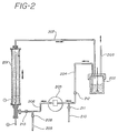
- Figure 2 is a schematic showing an overall arrangement for carbon monoxide tetramerization.
- Figure 3 is a sectional view of another embodiment of the electrolytic cell.
- cathode 101 is a conductive element capable of withstanding high pressure and corrosive materials.
- cathode 101 is a pipe, for example, a 316 stainless steel pipe although other materials can also be used.
- the dimensions of the cathode are not critical aside from the constraints imposed by high pressure operations, but rather will depend upon factors such as production capacity.
- anode 102 Positioned within and along the center longitudinal axis of cathode 101 is anode 102 which is a rod of anode material which dissolves under the application of a positive charge.
- anode 102 is an aluminum or magnesium rod.
- Current feeder 103 is constructed of stiff, electrically conducting material such as stainless steel and is appropriately wrapped with an insulating layer of tape, tubing or both - eg., Teflon tape, heat shrink plastic tubing, and the like which is of a type that is not attacked by the electrolyte mixture during use.
- Anode 102 is securely fastened to current feeder 103 at 104 by any convenient means including forcing the current feeder into a smooth-bore hole in the anode or screwing a threaded current feeder into a threaded hole in the anode.
- Use of threaded parts is especially desirable since ease of anode replacement is enhanced.
- anode 102 is threaded such that it can be advanced within the reaction zone without interrupting operation thus providing a continuous source of anode material to replenish that which is consumed without process disruption.
- Means are provided for introduction of electrolyte solution into the cathode 101 at 106.
- Preferably stainless steel tee 107 is provided through which electrolyte is introduced into the annular reaction zone 108 which is defined by the inner wall of cathode pipe 101 and the outer surface of anode rod 102.
- Means are provided for the withdrawal of product-containing electrolyte at 109.
- pipe 101 is flanged at 110 and 111 with appropriate compression fittings 112 and reducing bushing 113 provided to insure the integrity of the system.
- the electrolytic cell is operated with cathode 101 in the vertical position with electrolyte entering at the bottom and passing upwardly to exit at the top in order to avoid accumulation of squarate solids.
- Other positions can, however, be employed.
- the current feeder 103 is connected to a positive source of direct electrical current (not shown) while cathode 101 is connected to the negative pole (not shown).
- FIG 2 shows an overall system for the electrolytic tetramerization of carbon monoxide in which cell 201 is that described in Figure 1.
- stirred autoclave 202 made of corrosion and pressure resistant material such as stainless steel. Contained in autoclave 202 is the electrolyte solution maintained under continuous carbon monoxide pressure via line 203.
- Electrolyte solution containing carbon monoxide is passed from autoclave 202 via line 204, gear pump 205, and line 206 to the inlet of cell 201. Said inlet is at 106 on Figure 1.
- the electrolyte containing carbon monoxide passes upwardly through the annular space defined by the cathode pipe (101 from Figure 1) and the anode rod (102 from Figure 1) while a direct current of electricity is passing from anode to the cathode, whereby the carbon monoxide undergoes electrolytic tetramerization.
- the anode is consumed with formation of the squarate ion of the anode material - eg., magnesium squarate where a magnesium anode is employed - as product.
- the product-containing electrolyte passes out of the cell at 109 of Figure 1 and is transported via line 207 to autoclave 202.
- a portion of the circulating mixture is withdrawn via valve means 208 and line 209 and passes to product recovery and purification (not shown).
- product recovery and purification (not shown).
- the procedures set forth in U.S. patent 4,523,980 are illustrative of suitable and preferred recovery techniques.
- Fresh electrolyte in amount necessary to balance that removed is added via line 210 and valve means 211.
- product is removed and make-up electrolyte is added continuously although semi-continuous or batch modes can be employed.
- a number of cells are provided in parallel. Since the anode is consumed during the electrolytic carbon monoxide tetramerization it is necessary from time to time to replace the anode in a particular cell. Where there are a number of cells in parallel, anode replacement can be carried out as a scheduled matter without disruption of the process. As shown in Figure 2, a particular cell can be isolated by closing valve means 212 and 213 while other cells remain in operation. The isolated cell can be vented and the anode replaced quickly and conveniently as a matter of standard operation.
- the electrolytic conversion of carbon monoxide is a very rapid reaction.
- low to moderate pressures of carbon monoxide eg. 4.83 x 10⁶ Pa (700 psi.)
- the reaction tends to take place primarily near the end of the anode at the inlet point with anode attack in that zone. This can result in uneven conversion of the anode which can be a disadvantage in that more frequent anode replacement may be required.
- raising the CO pressure eg. to about 10.34 x 10⁶ Pa (1500 psi). or so, this uneven loss of anode can be substantially overcome.
- more CO is available for reaction and fairly even anode attack over the entire length of the anode can be achieved.
- a cell configuration such as is shown in Figure 3 can be employed.
- multiple inlet means 306 are provided along the cathode for parallel introduction of the electrolyte solution.
- Low CO partial pressures and therefore low system pressures can be used while still achieving uniform anode consumption with cells having this configuration.
- the invention is further illustrated by the following example.
- a high pressure, continuous electrochemical reactor cell is constructed as described in Figure 1 using, as a cathode, a 316 stainless steel schedule 40 pipe of 19.05 mm (0.75 inch) inner diameter. It is fitted with flanges and pressure fittings such that the interior length is equivalent to a wetted surface area of 18238.67 mm2 (28.27 square inches).
- an 10.41 mm (0.41 inch) diameter magnesium rod is secured along the longitudinal center line of the cathode pipe by insulated positioning means.
- a threaded stainless steel current feeder rod is screwed into a threaded recovery hole in the anode.
- the pressure tight insulating Conax fittings are secured and tested to 11.38 x 10⁶ Pa (1650 pounds per square inch) gauge pressure with nitrogen.
- the reactor is then connected to an electrolysis system as described by Figure 2 using a 300 cubic centimeter, 316L stainless steel Autoclave Engineers Magnidrive autoclave as the carbon monoxide dissolution vessel; a Micropump Model 210 gear pump is connected to the loop to circulate the electrolysis solution.
- the system is charged with 350 milliliters of isobutyronitrile and 12 grams of tetrabutyl ammonium iodide.
- the circulation pump is started at a setting determined previously to achieve a circulation rate through the reaction loop of 1600 milliliters per minute.
- the system is then pressured with CP grade carbon monoxide from cylinders via the dissolution tank to a system pressure of 9.79 x 10⁶ Pa (1420 pounds per square inch) gauge.
- the cell voltage is set at 10 volts and is applied from a filtered DC power supply unit, Model D-612T of Epsco Incorporated.
- the concentration of squaric acid in the circulating electrolysis solution reaches about 25 weight percent.
- the bleed valve is opened to purge electrolysis solution at a rate of 75 milliliters per hour.
- the purged solution is filtered; the solids are accumulated and the filtrate is put into a glass burette from which the filtrate is pumped back into the electrolysis loop at essentially the same rate as the purge is withdrawn, using a Milton Roy Instrument Mini Pump.
- the solids contain 31.83 grams of squaric acid, equivalent to 0.28 moles.
- the current efficiency of squaric acid production is therefore 47.9 percent.
- TEFLON is a trade mark which may be registered in some of the States designated in the application.
Landscapes
- Chemical & Material Sciences (AREA)
- Organic Chemistry (AREA)
- Engineering & Computer Science (AREA)
- Chemical Kinetics & Catalysis (AREA)
- Electrochemistry (AREA)
- Materials Engineering (AREA)
- Metallurgy (AREA)
- Electrolytic Production Of Non-Metals, Compounds, Apparatuses Therefor (AREA)
Description
- The present invention relates to an electrolytic cell which is especially adapted for the high pressure electrolytic coupling of carbon monoxide to squaric acid, and a system incorporating such cell.
- Processes are known whereby carbon monoxide can be electrolytically coupled to form squaric acid.
- U.S. patent 3,833,489 to Ercoli et al. describes the electrochemical cyclotetramerization of carbon monoxide to produce the squarate ion. Operations using corrodable or non-corrodable anodes are described. Solvents such as amides of phosphoric acid or carboxylic acids, aliphatic ethers, cyclic ethers, liquid polyethers and anhydrous ammonia are taught. Materials such as halides are added to enhance conductivity.
- The apparatus described in the above patent is a pressure resistant electrolytic cell in which may be arranged a cylindrical graphite anode and a stainless steel cathode which is also the container. A stirrer is provided and there are introduced into the cell under nitrogen atmosphere auxiliary electrolyte and solvent. The cell is sealed and immersed in a temperature control bath. Carbon monoxide is charged until a certain pressure is attained and direct current is then passed through the solution for the time required for the reaction. Upon completion of the reaction, current circulation is stopped, gas is discharged and the suspension in the cathodic zone is removed and subjected to various recovery and work-up procedures.
- It will be apparent that the apparatus described above is not suitable for continuous, commercial-type operations.
- U.S. patents 4,461,681 and 4,523,980 of James J. Barber are directed to the electrolytic tetramerization of carbon monoxide using anhydrous nitrile solvents and to the separation and recovery of high purity squaric acid from squarate containing solids from the electrolytic reaction. The apparatus described for the electrolytic tetramerization is, illustratively, a Paar bomb equipped with a magnetic stirring vane. An aluminum, titanium or magnesium rod connected via a bulkhead electrical adapter to the positive pole of a power supply is used as anode. After being charged with solvent and auxiliary electrolyte, the bomb was sealed, connected to the negative pole of the power supply, and pressurized with carbon monoxide. Direct current was applied until a certain charge had passed. Gas was vented, and solids were separated as by centrifugation.
- It will be apparent that improvements in the apparatus described above are desirable for continuous commercial operations.
- The present invention relates to a novel electrolytic cell which is especially adapted for continuous, high pressure electrolytic coupling or tetramerization of carbon monoxide to the squarate ion.
- According to the present invention there is provided an apparatus suitable for the continuous eletrolytic conversion of carbon monoxide ion to squaric acid which comprises an electrolytic cell capable of operating at high pressure and having a cylindrical wall which defines an electrolyte containing zone and provides a corrosion resistant cathode means for the cell, said cell further comprising:
a consumable anode means positioned within said cathode means, said cathode and anode means together defining an electrolytic reaction zone;
inlet means for the continuous introduction of liquid electrolyte containing carbon monoxide into said reaction zone;
outlet means for the continuous removal of liquid electrolyte and solid reaction product from said reaction zone;
means for passing direct current from said anode means to said cathode means;
means for continuously separating product-containing electrolyte; means for continuously circulating electrolyte from the outlet means to the inlet means; and means for introducing carbon monoxide into the circulating electrolyte. - The apparatus preferably has a plurality of inlet means for the continuous introduction of liquid electrolyte into said reaction zone and the consumble anode means is preferably adapted to be threadedly advanced in said reaction zone.
- The apparatus may comprise a plurality of such cells arranged in parallel.
- Figure 1 is a sectional view of an embodiment of the electrolytic cell of the invention.
- Figure 2 is a schematic showing an overall arrangement for carbon monoxide tetramerization.
- Figure 3 is a sectional view of another embodiment of the electrolytic cell.
- Referring to Figure 1,
cathode 101 is a conductive element capable of withstanding high pressure and corrosive materials. Preferablycathode 101 is a pipe, for example, a 316 stainless steel pipe although other materials can also be used. The dimensions of the cathode are not critical aside from the constraints imposed by high pressure operations, but rather will depend upon factors such as production capacity. - Positioned within and along the center longitudinal axis of
cathode 101 isanode 102 which is a rod of anode material which dissolves under the application of a positive charge. Preferablyanode 102 is an aluminum or magnesium rod. - Current is passed to
anode 102 bycurrent feeder 103 which enters the cell through an electricallyinsulated gland 104, which is preferably a Conax gland, containing a teflon sealant ring. Other glands which function in an equivalent way can be employed. -
Current feeder 103 is constructed of stiff, electrically conducting material such as stainless steel and is appropriately wrapped with an insulating layer of tape, tubing or both - eg., Teflon tape, heat shrink plastic tubing, and the like which is of a type that is not attacked by the electrolyte mixture during use. -
Anode 102 is securely fastened tocurrent feeder 103 at 104 by any convenient means including forcing the current feeder into a smooth-bore hole in the anode or screwing a threaded current feeder into a threaded hole in the anode. Use of threaded parts is especially desirable since ease of anode replacement is enhanced. - In an especially preferred practice,
anode 102 is threaded such that it can be advanced within the reaction zone without interrupting operation thus providing a continuous source of anode material to replenish that which is consumed without process disruption. - Means are provided for introduction of electrolyte solution into the
cathode 101 at 106. Preferablystainless steel tee 107 is provided through which electrolyte is introduced into theannular reaction zone 108 which is defined by the inner wall ofcathode pipe 101 and the outer surface ofanode rod 102. - Means are provided for the withdrawal of product-containing electrolyte at 109. Preferably,
pipe 101 is flanged at 110 and 111 withappropriate compression fittings 112 and reducingbushing 113 provided to insure the integrity of the system. - Preferably, the electrolytic cell is operated with
cathode 101 in the vertical position with electrolyte entering at the bottom and passing upwardly to exit at the top in order to avoid accumulation of squarate solids. Other positions can, however, be employed. - The
current feeder 103 is connected to a positive source of direct electrical current (not shown) whilecathode 101 is connected to the negative pole (not shown). - Figure 2 shows an overall system for the electrolytic tetramerization of carbon monoxide in which cell 201 is that described in Figure 1. Referring to Figure 2, there is provided
stirred autoclave 202 made of corrosion and pressure resistant material such as stainless steel. Contained inautoclave 202 is the electrolyte solution maintained under continuous carbon monoxide pressure vialine 203. - Electrolyte solution containing carbon monoxide is passed from
autoclave 202 vialine 204,gear pump 205, andline 206 to the inlet of cell 201. Said inlet is at 106 on Figure 1. - As shown schematically in Figure 2, the electrolyte containing carbon monoxide passes upwardly through the annular space defined by the cathode pipe (101 from Figure 1) and the anode rod (102 from Figure 1) while a direct current of electricity is passing from anode to the cathode, whereby the carbon monoxide undergoes electrolytic tetramerization. During the electrolytic conversion, the anode is consumed with formation of the squarate ion of the anode material - eg., magnesium squarate where a magnesium anode is employed - as product.
- The product-containing electrolyte passes out of the cell at 109 of Figure 1 and is transported via
line 207 toautoclave 202. - High circulation rates are maintained in order to avoid the accumulation of product solids as well as coproduct material in the system. It should be noted that viscous by-products are formed during the electrochemical reaction which have a tendency to deposit on electrode surfaces and interfere with operations. Problems associated with these by-products are substantially avoided through use of the apparatus of this invention, especially where the upright configuration of
cell 101 is employed and high electrolyte solution circulation rates are maintained. - A portion of the circulating mixture is withdrawn via valve means 208 and
line 209 and passes to product recovery and purification (not shown). The procedures set forth in U.S. patent 4,523,980 are illustrative of suitable and preferred recovery techniques. - Fresh electrolyte in amount necessary to balance that removed is added via
line 210 and valve means 211. - Preferably, product is removed and make-up electrolyte is added continuously although semi-continuous or batch modes can be employed.
- In especially preferred practice, a number of cells are provided in parallel. Since the anode is consumed during the electrolytic carbon monoxide tetramerization it is necessary from time to time to replace the anode in a particular cell. Where there are a number of cells in parallel, anode replacement can be carried out as a scheduled matter without disruption of the process. As shown in Figure 2, a particular cell can be isolated by closing valve means 212 and 213 while other cells remain in operation. The isolated cell can be vented and the anode replaced quickly and conveniently as a matter of standard operation.
- The electrolytic conversion of carbon monoxide is a very rapid reaction. Where low to moderate pressures of carbon monoxide are employed, eg. 4.83 x 10⁶ Pa (700 psi.), in the apparatus shown in Figure 1 the reaction tends to take place primarily near the end of the anode at the inlet point with anode attack in that zone. This can result in uneven conversion of the anode which can be a disadvantage in that more frequent anode replacement may be required. By raising the CO pressure, eg. to about 10.34 x 10⁶ Pa (1500 psi). or so, this uneven loss of anode can be substantially overcome. At the higher CO pressures, more CO is available for reaction and fairly even anode attack over the entire length of the anode can be achieved.
- Where both even anode attack and relatively low system pressures are desired, a cell configuration such as is shown in Figure 3 can be employed. In this configuration, multiple inlet means 306 are provided along the cathode for parallel introduction of the electrolyte solution. Low CO partial pressures and therefore low system pressures can be used while still achieving uniform anode consumption with cells having this configuration.
- The invention is further illustrated by the following example.
- A high pressure, continuous electrochemical reactor cell is constructed as described in Figure 1 using, as a cathode, a 316 stainless steel schedule 40 pipe of 19.05 mm (0.75 inch) inner diameter. It is fitted with flanges and pressure fittings such that the interior length is equivalent to a wetted surface area of 18238.67 mm² (28.27 square inches).
- As the anode, an 10.41 mm (0.41 inch) diameter magnesium rod is secured along the longitudinal center line of the cathode pipe by insulated positioning means. A threaded stainless steel current feeder rod is screwed into a threaded recovery hole in the anode. The pressure tight insulating Conax fittings are secured and tested to 11.38 x 10⁶ Pa (1650 pounds per square inch) gauge pressure with nitrogen.
- The reactor is then connected to an electrolysis system as described by Figure 2 using a 300 cubic centimeter, 316L stainless steel Autoclave Engineers Magnidrive autoclave as the carbon monoxide dissolution vessel; a
Micropump Model 210 gear pump is connected to the loop to circulate the electrolysis solution. - The system is charged with 350 milliliters of isobutyronitrile and 12 grams of tetrabutyl ammonium iodide. The circulation pump is started at a setting determined previously to achieve a circulation rate through the reaction loop of 1600 milliliters per minute. The system is then pressured with CP grade carbon monoxide from cylinders via the dissolution tank to a system pressure of 9.79 x 10⁶ Pa (1420 pounds per square inch) gauge. The cell voltage is set at 10 volts and is applied from a filtered DC power supply unit, Model D-612T of Epsco Incorporated.
- After 2 hours of closed loop operation the concentration of squaric acid in the circulating electrolysis solution reaches about 25 weight percent. At that point the bleed valve is opened to purge electrolysis solution at a rate of 75 milliliters per hour.
- The purged solution is filtered; the solids are accumulated and the filtrate is put into a glass burette from which the filtrate is pumped back into the electrolysis loop at essentially the same rate as the purge is withdrawn, using a Milton Roy Instrument Mini Pump.
- The run is continued in this manner for a total of 14 hours. Over that period, the current passed amounts to 1.165 Faradays. A total of 122.95 grams of solids are recovered.
- The solids contain 31.83 grams of squaric acid, equivalent to 0.28 moles. The current efficiency of squaric acid production is therefore 47.9 percent.
- TEFLON is a trade mark which may be registered in some of the States designated in the application.
Claims (4)
- An apparatus suitable for the continuous electrolytic conversion of carbon monoxide ion to squaric acid which comprises an
electrolytic cell capable of operating at high pressure and having a cylindrical wall which defines an electrolyte containing zone and provides a corrosion resistant cathode means for the cell, said cell further comprising:
a consumable anode means positioned within said cathode means, said cathode and anode means together defining an electrolytic reaction zone;
inlet means for the continuous introduction of liquid electrolyte containing carbon monoxide into said reaction zone;
outlet means for the continuous removal of liquid electrolyte and solid reaction product from said reaction zone;
means for passing direct current from said anode means to said cathode means;
means for continuously separating product-containing electrolyte; means for continuously circulating electrolyte from the outlet means to the inlet means; and means for introducing carbon monoxide into the circulating electrolyte. - An apparatus according to claim 1, wherein the cell has a plurality of inlet means for the continuous introduction of liquid electrolyte into said reaction zone.
- An apparatus according to Claim 1, wherein said consumable anode means is adapted to be threadedly advanced in said reaction zone.
- An apparatus according to any one of Claims 1 to 3, comprising a plurality of electrolytic cells arranged in parallel.
Applications Claiming Priority (2)
| Application Number | Priority Date | Filing Date | Title |
|---|---|---|---|
| US172254 | 1988-03-23 | ||
| US07/172,254 US4834858A (en) | 1988-03-23 | 1988-03-23 | Electrolytic reactor |
Publications (2)
| Publication Number | Publication Date |
|---|---|
| EP0334635A1 EP0334635A1 (en) | 1989-09-27 |
| EP0334635B1 true EP0334635B1 (en) | 1995-01-18 |
Family
ID=22626928
Family Applications (1)
| Application Number | Title | Priority Date | Filing Date |
|---|---|---|---|
| EP89302845A Expired - Lifetime EP0334635B1 (en) | 1988-03-23 | 1989-03-22 | Electrolytic reactor |
Country Status (4)
| Country | Link |
|---|---|
| US (1) | US4834858A (en) |
| EP (1) | EP0334635B1 (en) |
| JP (1) | JPH01275790A (en) |
| DE (1) | DE68920611T2 (en) |
Families Citing this family (8)
| Publication number | Priority date | Publication date | Assignee | Title |
|---|---|---|---|---|
| DE4444667A1 (en) * | 1994-12-15 | 1996-06-20 | Studiengesellschaft Kohle Mbh | Electrolysis cell for the electrochemical production of metal alcoholates |
| ATE504674T1 (en) * | 2003-02-21 | 2011-04-15 | Avalence Llc | ELECTROLYSIS APPARATUS AND METHOD FOR PRODUCING HYDROGEN |
| USD527662S1 (en) * | 2004-10-29 | 2006-09-05 | Zodiac Pool Care, Inc. | Electrode housing and indicator |
| US7211176B2 (en) * | 2004-11-02 | 2007-05-01 | Zodiac Pool Care, Inc. | Replaceable chlorinator electrode assembly |
| JP5364126B2 (en) * | 2011-05-24 | 2013-12-11 | 上村工業株式会社 | Electrolytic regeneration processing unit and electrolytic regeneration processing apparatus including the same |
| US10689768B2 (en) * | 2014-08-01 | 2020-06-23 | Sogang University Research Foundation | Amalgam electrode, producing method thereof, and method of electrochemical reduction of carbon dioxide using the same |
| CN114959752B (en) * | 2022-04-29 | 2024-02-13 | 浙江工业大学 | Electrochemical reactor, system and application in electrolytic synthesis of 2,6-dichlorobenzonitrile |
| WO2025040673A1 (en) * | 2023-08-24 | 2025-02-27 | Avantium Knowledge Centre B.V. | Electrolysis cell for electrosynthesis of organic or organometallic compounds |
Family Cites Families (6)
| Publication number | Priority date | Publication date | Assignee | Title |
|---|---|---|---|---|
| DE1471642B2 (en) * | 1963-12-04 | 1971-06-16 | Electro Chlor AG. Basel (Schweiz) | ELECTROLYSIS CELL |
| BE786650A (en) * | 1971-07-24 | 1973-01-24 | Ercoli Raffaele | PROCESS FOR PREPARING SQUARIC ACID |
| US3957596A (en) * | 1974-05-21 | 1976-05-18 | Ontario Research Foundation | Production of fluorinated hydrocarbons |
| US3953315A (en) * | 1974-12-23 | 1976-04-27 | Eastman Kodak Company | Electrolytic cell construction |
| US4253925A (en) * | 1979-10-22 | 1981-03-03 | The Board Of Trustees Of The Leland Stanford Junior University | Method and apparatus for catalytic dissociation of NO |
| FR2586710B1 (en) * | 1985-09-05 | 1990-03-30 | Poudres & Explosifs Ste Nale | ORGANIC ELECTROLYSIS CELL WITH CONSUMABLE ELECTRODE |
-
1988
- 1988-03-23 US US07/172,254 patent/US4834858A/en not_active Expired - Fee Related
-
1989
- 1989-03-22 DE DE68920611T patent/DE68920611T2/en not_active Expired - Fee Related
- 1989-03-22 JP JP1070312A patent/JPH01275790A/en active Pending
- 1989-03-22 EP EP89302845A patent/EP0334635B1/en not_active Expired - Lifetime
Also Published As
| Publication number | Publication date |
|---|---|
| DE68920611T2 (en) | 1995-05-18 |
| DE68920611D1 (en) | 1995-03-02 |
| US4834858A (en) | 1989-05-30 |
| EP0334635A1 (en) | 1989-09-27 |
| JPH01275790A (en) | 1989-11-06 |
Similar Documents
| Publication | Publication Date | Title |
|---|---|---|
| EP0368812B1 (en) | Method and apparatus for electrolyzing water | |
| SUDOH et al. | Electrochemical production of hydrogen peroxide by reduction of oxygen | |
| EP0212240A1 (en) | Apparatus for the electrolysis of solutions | |
| CN1048294C (en) | Electrochemical fluorination electrolyzer | |
| US4379043A (en) | Water-decomposition and gas-generating apparatus | |
| US4019968A (en) | Electrochemical cell | |
| CA1065797A (en) | Electrochemical cell with bipolar electrodes | |
| EP0334635B1 (en) | Electrolytic reactor | |
| US6287448B1 (en) | Electrochemical production of lithium using a lithium amalgam anode | |
| EP0565330B1 (en) | A process and an electrolytic cell for the production of fluorine | |
| Chaussard et al. | Scale-up of electrocarboxylation reactions with a consumable anode | |
| US4455208A (en) | Apparatus for electrolysis using two electrolytically conducting phases | |
| US4046653A (en) | Novel electrolysis method and apparatus | |
| US3883415A (en) | Multiple vertical diaphragm type electrolytic cell for producing caustic soda | |
| Walsh et al. | The electrolytic removal of gold from spent electroplating liquors | |
| US2512973A (en) | Process for making perchlorates | |
| US4652355A (en) | Flow-through electrolytic cell | |
| US3450623A (en) | Electrolytic apparatus for the regeneration of chromium salt solutions | |
| US2592686A (en) | Electrolytic production of fatty | |
| US4705564A (en) | Flow-through electrolytic cell | |
| GB1443690A (en) | Electrolytic cells | |
| US4971675A (en) | Electrolyzer for purification of fluids | |
| US3994788A (en) | Electrochemical oxidation of phenol | |
| US3262871A (en) | Preparation of phosphine | |
| RU2089670C1 (en) | Process of generation of hydrogen |
Legal Events
| Date | Code | Title | Description |
|---|---|---|---|
| PUAI | Public reference made under article 153(3) epc to a published international application that has entered the european phase |
Free format text: ORIGINAL CODE: 0009012 |
|
| AK | Designated contracting states |
Kind code of ref document: A1 Designated state(s): BE DE FR GB IT NL |
|
| 17P | Request for examination filed |
Effective date: 19900315 |
|
| 17Q | First examination report despatched |
Effective date: 19920423 |
|
| GRAA | (expected) grant |
Free format text: ORIGINAL CODE: 0009210 |
|
| AK | Designated contracting states |
Kind code of ref document: B1 Designated state(s): BE DE FR GB IT NL |
|
| ITF | It: translation for a ep patent filed | ||
| REF | Corresponds to: |
Ref document number: 68920611 Country of ref document: DE Date of ref document: 19950302 |
|
| ET | Fr: translation filed | ||
| PLBE | No opposition filed within time limit |
Free format text: ORIGINAL CODE: 0009261 |
|
| STAA | Information on the status of an ep patent application or granted ep patent |
Free format text: STATUS: NO OPPOSITION FILED WITHIN TIME LIMIT |
|
| 26N | No opposition filed | ||
| PGFP | Annual fee paid to national office [announced via postgrant information from national office to epo] |
Ref country code: GB Payment date: 19990311 Year of fee payment: 11 |
|
| PGFP | Annual fee paid to national office [announced via postgrant information from national office to epo] |
Ref country code: FR Payment date: 19990330 Year of fee payment: 11 |
|
| PGFP | Annual fee paid to national office [announced via postgrant information from national office to epo] |
Ref country code: NL Payment date: 19990331 Year of fee payment: 11 |
|
| PGFP | Annual fee paid to national office [announced via postgrant information from national office to epo] |
Ref country code: BE Payment date: 19990407 Year of fee payment: 11 |
|
| PGFP | Annual fee paid to national office [announced via postgrant information from national office to epo] |
Ref country code: DE Payment date: 19990430 Year of fee payment: 11 |
|
| PG25 | Lapsed in a contracting state [announced via postgrant information from national office to epo] |
Ref country code: GB Free format text: LAPSE BECAUSE OF NON-PAYMENT OF DUE FEES Effective date: 20000322 |
|
| PG25 | Lapsed in a contracting state [announced via postgrant information from national office to epo] |
Ref country code: BE Free format text: LAPSE BECAUSE OF NON-PAYMENT OF DUE FEES Effective date: 20000331 |
|
| BERE | Be: lapsed |
Owner name: MONTVALE PROCESS CY Effective date: 20000331 |
|
| PG25 | Lapsed in a contracting state [announced via postgrant information from national office to epo] |
Ref country code: NL Free format text: LAPSE BECAUSE OF NON-PAYMENT OF DUE FEES Effective date: 20001001 |
|
| GBPC | Gb: european patent ceased through non-payment of renewal fee |
Effective date: 20000322 |
|
| PG25 | Lapsed in a contracting state [announced via postgrant information from national office to epo] |
Ref country code: FR Free format text: LAPSE BECAUSE OF NON-PAYMENT OF DUE FEES Effective date: 20001130 |
|
| NLV4 | Nl: lapsed or anulled due to non-payment of the annual fee |
Effective date: 20001001 |
|
| REG | Reference to a national code |
Ref country code: FR Ref legal event code: ST |
|
| PG25 | Lapsed in a contracting state [announced via postgrant information from national office to epo] |
Ref country code: DE Free format text: LAPSE BECAUSE OF NON-PAYMENT OF DUE FEES Effective date: 20010103 |
|
| PG25 | Lapsed in a contracting state [announced via postgrant information from national office to epo] |
Ref country code: IT Free format text: LAPSE BECAUSE OF NON-PAYMENT OF DUE FEES;WARNING: LAPSES OF ITALIAN PATENTS WITH EFFECTIVE DATE BEFORE 2007 MAY HAVE OCCURRED AT ANY TIME BEFORE 2007. THE CORRECT EFFECTIVE DATE MAY BE DIFFERENT FROM THE ONE RECORDED. Effective date: 20050322 |