EP0334541A1 - Machine tool error compensation systems and the like - Google Patents
Machine tool error compensation systems and the like Download PDFInfo
- Publication number
- EP0334541A1 EP0334541A1 EP89302541A EP89302541A EP0334541A1 EP 0334541 A1 EP0334541 A1 EP 0334541A1 EP 89302541 A EP89302541 A EP 89302541A EP 89302541 A EP89302541 A EP 89302541A EP 0334541 A1 EP0334541 A1 EP 0334541A1
- Authority
- EP
- European Patent Office
- Prior art keywords
- signal
- analogue
- error
- tool
- digital
- Prior art date
- Legal status (The legal status is an assumption and is not a legal conclusion. Google has not performed a legal analysis and makes no representation as to the accuracy of the status listed.)
- Withdrawn
Links
- 230000033001 locomotion Effects 0.000 claims description 17
- 238000012937 correction Methods 0.000 claims description 14
- 238000000034 method Methods 0.000 claims description 14
- 230000004044 response Effects 0.000 claims description 14
- 238000005259 measurement Methods 0.000 claims description 12
- 230000000694 effects Effects 0.000 claims description 10
- 238000012544 monitoring process Methods 0.000 claims description 2
- 230000003287 optical effect Effects 0.000 description 6
- 238000010586 diagram Methods 0.000 description 4
- 238000012986 modification Methods 0.000 description 4
- 230000004048 modification Effects 0.000 description 4
- 238000013459 approach Methods 0.000 description 3
- 230000008901 benefit Effects 0.000 description 3
- 125000004122 cyclic group Chemical group 0.000 description 3
- 238000006073 displacement reaction Methods 0.000 description 3
- 230000006870 function Effects 0.000 description 3
- 238000003754 machining Methods 0.000 description 3
- 238000004458 analytical method Methods 0.000 description 2
- 238000004364 calculation method Methods 0.000 description 2
- 230000008859 change Effects 0.000 description 2
- 230000000737 periodic effect Effects 0.000 description 2
- 238000012545 processing Methods 0.000 description 2
- 230000002441 reversible effect Effects 0.000 description 2
- 230000003044 adaptive effect Effects 0.000 description 1
- 230000004075 alteration Effects 0.000 description 1
- 238000013461 design Methods 0.000 description 1
- 230000009977 dual effect Effects 0.000 description 1
- 238000002347 injection Methods 0.000 description 1
- 239000007924 injection Substances 0.000 description 1
- 230000007246 mechanism Effects 0.000 description 1
- 230000000750 progressive effect Effects 0.000 description 1
- 239000000523 sample Substances 0.000 description 1
- 230000006641 stabilisation Effects 0.000 description 1
- 230000001052 transient effect Effects 0.000 description 1
Images
Classifications
-
- G—PHYSICS
- G05—CONTROLLING; REGULATING
- G05B—CONTROL OR REGULATING SYSTEMS IN GENERAL; FUNCTIONAL ELEMENTS OF SUCH SYSTEMS; MONITORING OR TESTING ARRANGEMENTS FOR SUCH SYSTEMS OR ELEMENTS
- G05B19/00—Programme-control systems
- G05B19/02—Programme-control systems electric
- G05B19/18—Numerical control [NC], i.e. automatically operating machines, in particular machine tools, e.g. in a manufacturing environment, so as to execute positioning, movement or co-ordinated operations by means of programme data in numerical form
- G05B19/19—Numerical control [NC], i.e. automatically operating machines, in particular machine tools, e.g. in a manufacturing environment, so as to execute positioning, movement or co-ordinated operations by means of programme data in numerical form characterised by positioning or contouring control systems, e.g. to control position from one programmed point to another or to control movement along a programmed continuous path
- G05B19/21—Numerical control [NC], i.e. automatically operating machines, in particular machine tools, e.g. in a manufacturing environment, so as to execute positioning, movement or co-ordinated operations by means of programme data in numerical form characterised by positioning or contouring control systems, e.g. to control position from one programmed point to another or to control movement along a programmed continuous path using an incremental digital measuring device
- G05B19/23—Numerical control [NC], i.e. automatically operating machines, in particular machine tools, e.g. in a manufacturing environment, so as to execute positioning, movement or co-ordinated operations by means of programme data in numerical form characterised by positioning or contouring control systems, e.g. to control position from one programmed point to another or to control movement along a programmed continuous path using an incremental digital measuring device for point-to-point control
- G05B19/231—Numerical control [NC], i.e. automatically operating machines, in particular machine tools, e.g. in a manufacturing environment, so as to execute positioning, movement or co-ordinated operations by means of programme data in numerical form characterised by positioning or contouring control systems, e.g. to control position from one programmed point to another or to control movement along a programmed continuous path using an incremental digital measuring device for point-to-point control the positional error is used to control continuously the servomotor according to its magnitude
- G05B19/232—Numerical control [NC], i.e. automatically operating machines, in particular machine tools, e.g. in a manufacturing environment, so as to execute positioning, movement or co-ordinated operations by means of programme data in numerical form characterised by positioning or contouring control systems, e.g. to control position from one programmed point to another or to control movement along a programmed continuous path using an incremental digital measuring device for point-to-point control the positional error is used to control continuously the servomotor according to its magnitude with speed feedback only
Definitions
- This invention relates to error compensation systems for correcting or reducing positioning errors which arise when a movable body is positioned along a control axis by a servo motor/actuator means and particularly, but not exclusively, to machine tool error compensation systems for correcting or reducing positioning errors associated with the control of the tool position.
- This invention relates more particularly, but not exclusively, to a numerically controlled machine tool of the kind comprising a tool holder driven by a tool drive, a tool positioning servo motor/actuator operating the tool drive and controlled in response to an analogue position error signal, a position transducer responsive to the position of the tool, tool holder or tool drive to provide a position feedback signal, and a numerically controlled controller responsive to a position demand signal and to the position feedback signal to produce the analogue position error signal.
- a machine tool will hereinafter be referred to as a "machine tool of the kind set forth”.
- the servo motor/actuator can be an electric servo motor or an electro-hydraulic servo motor/actuator.
- a velocity transducer is arranged to be responsive to the velocity of the tool drive or associated component to provide a velocity feedback signal, and a summation means is provided for combining the analogue position error signal with the velocity feedback signal to produce an analogue servo drive signal which is applied to the servo motor/actuator.
- the position transducer may be a digital transducer (encoder) or an analogue transducer (synchro, resolver etc.)
- Some current high cost CNC machine controllers provide a degree of attempted compensation for errors in the mechanical movement of the tool.
- the compensation system employed generally involves measuring the tool positioning error at only a limited number of tool slide positions on a single axis, and those point errors are then used by the CNC controller to correct internally of the controller the computation of the position error signal applied to the tool positioning servo associated with that tool slide.
- No attempt is made in such systems to interpolate between or extrapolate from the point errors each error value (converted into units of servo counts) is simply added to the "following error" as the slide physically passes the corresponding correction point during the execution of the programmed axis move or job operation.
- an error value is employed without modification until the next correction point is reached, whereupon the new error measurement is used until a subsequent correction point is reached. It will be appreciated that this method does not produce accurate error compensation for tool slide positions intermediate to the correction points.
- the "following error” is the lag of the actual tool or tool slide position (depending upon the point of measurement by the position transducer i.e. whether the transducer is associated with the tool or with the tool slide respectively) from the demand position at any instant of time (and is proportional to the velocity of axis motion).
- the position demand signal is incrementally summed with the position feedback signal to produce the following error.
- the following error is then used to produce the position error signal to drive the axis servo in the next servo cycle, the change from a following error signal to a position error signal involving a change of units.
- the output of the controller is an analogue position error signal which is applied to the input of the servo (in conjunction with a velocity feedback signal).
- the output stage of such a controller is a DAC typically with a resolution of no more than 12 bits.
- the maximum traverse rate of a high cost servo system is, say, 5000 mm/min.
- a first aspect of the present invention is based on our idea of generating an analogue error compensation signal which is used to modify the analogue servo drive signal.
- a correction signal with the (uncorrected) analogue position error signal generated by the (uncompensated) CNC controller, or with the velocity feedback signal.
- one application of our invention is to existing machine tools where our compensation unit can be provided without any modifications being made to the CNC controller or to the tool slide servo system.
- a method of compensating for the effect of positioning errors in the positioning of a movable body in a body positioning apparatus of the kind comprising a body drive for positioning the body along a control axis, a body positioning servo motor/actuator means operating the body drive and controlled in response to an analogue position error signal, a position transducer responsive to the position of the body, body holder or body drive, and a digital controller responsive to a position demand signal and to the position feedback signal to produce, through a digital to analogue convertor, the analogue position error signal, characterised in that the method comprises monitoring the output of the position transducer and computing or selecting an analogue error compensation amount for the body position on the basis of stored calibration data corresponding to the position transducer output, and using the analogue error compensation amount to modify the servo drive signal.
- a body positioning apparatus of the kind comprising a body carrier driven by a body drive for positioning the body along a control axis, a body positioning servo motor actuator means operating the body drive and controlled in response to an analogue position error signal, a position transducer responsive to the position of the body, body carrier or body drive, to provide a position feedback signal, and a digital controller having a digital to analogue convertor at its output, the controller being responsive to a position demand signal and to the position feedback signal to produce the analogue position error signal, the apparatus further comprising an error compensation means for compensating for or reducing the effect of repeatable errors in the positioning of the body, the error compensation means providing a correction or adjustment signal for modifying the control of the body position, characterised in that the error compensation means comprises a store of calibration data corresponding to the position transducer output, and the error compensation means provides an analogue error compensation amount which is summed with the analogue position error signal in producing the drive signal which is applied to the
- the compensation amount may, of course, be summed either with the position error signal or with the velocity feedback signal prior to summing of those signals, provided of course that the correct positive or negative sense is chosen.
- a significant advantage of making the compensation by modifying the analogue drive applied to the servo motor/actuator is that this can be done entirely independently of the controller operation itself which means that an existing or conventional controller can be employed, and no additional demand is made on the memory of the controller.
- the error compensation signal can be generated in an independent error compensation unit the output of which can readily be interfaced with the controller output. Such a unit can readily be applied to an existing or new machine tool to improve substantially the tool positioning accuracy.
- a positioning error correction unit adapted to be connected to a body positioning apparatus
- the body positioning apparatus being of the kind comprising a body carries driven by a body drive for positioning the body along a control axis, a body positioning servo motor/actuator means operating the body drive means and controlled in response to an analogue position error signal, a position transducer responsive to the position of the body, body carrier or body drive, to provide a position feedback signal, and a digital controller having a first digital to analogue convertor at its output, the controller being responsive to a position demand signal and to the position feedback signal to produce the analogue position error signal characterised in that the positioning error correction unit comprises an input for connection to the position transducer, a store for calibration data corresponding to the position transducer output, a digital processer for accessing the calibration data, and a second digital to analogue converter for providing an analogue output signal at an output connection of the unit, the output connection being adapted to be connected to a summation
- the controller is preferably a CNC (computer numerically controlled controller) but it could be a basic NC controller.
- a scaling factor or ratio is preferably provided between the units of the analogue error compensation signal and the units of the analogue position error signal. That is, for a given following error amount and equal compensation error amount, the analogue position error signal (corresponding to the following error) is arranged to be greater than the corresponding error compensation signal by a scaling factor f which is greater than unity.
- the scaling factor f is preferably greater than two.
- the scaling factor f is greater than four.
- the scaling factor f is preferably an integer.
- This scaling factor provides a ratio between the resolution of the analogue error compensation signal and the resolution of the position error signal in favour of the error compensation signal.
- the analogue error compensation signal (of high resolution) will dominate the position error signal (of lower resolution) and accordingly a high degree of accuracy of tool position can be achieved, despite the fact that a "low" resolution NC controller is employed.
- the stepped output of the digital to analogue converter of the controller will enter the zero deadband, but the error compensation signal will provide the small servo drive signal required to drive the tool to the demand position.
- the stored calibration data can include sets of reference values which correspond to some of the above error sources.
- items 4 and 6 would involve the use of additional transducers to measure temperature, and machine load respectively.
- the stored data is preferably in the form of a look-up table which is conveniently held in a programmable memory, such as an E-PROM.
- the data is loaded into the programmable memory in a calibration procedure during which the precise position of the tool and the angular and straightness errors relative to the machine bed measured, conveniently by a laser interferometer, and the corresponding output signal of the position transducer/s is recorded.
- error components (a) and (b) give 18 components in all, with (c) giving 3 components, to provide a total of 21 error components. Some of these may be irrelevant in practice depending upon their magnitude and the mechanical configuration of the machine.
- the following aspect of the invention is concerned with correcting for error component (5) listed above in a machine having at least two axes.
- an error compensation system for a numerically controlled machine tool comprises a programmable memory which has been loaded during a calibration procedure with a set of look up tables comprising (a) a set of relatively accurate measurements (or error components) for the tool position along a first axis each corresponding to (b) tool position transducer output values from a first transducer responsive to tool/tool holder/tool drive position on the first axis of movement (c) a set of error components for tool position along the first axis corresponding to (d) second tool position transducer output values from a second transducer responsive to tool/tool holder/tool drive position on a second axis of movement, the system including means adapted in use of the machine tool to take a value from the set (a) based on a measurement by the first transducer of the first axis position of the tool, and to modify that amount by taking an amount from set (c) corresponding to the measurement by the second transducer of the second axis position of the tool,
- An adaptive compensation algorithm is used to combine the various error components, which for a machine having several axes is a complex task.
- the look-up table/s produced in calibrating the tool slide/s can be used to correct the readings provided by the tool position transducers when the tool is replaced by a probe for checking the accuracy of a machined component.
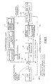
- Figure 1 shows the application of an error compensation unit 1 to an existing CNC machine comprising a tool slide 2, tool slide drive 3, drive motor 4 for the tool slide 2 and an uncompensated CNC controller 5, a drive amplifier 6 being positioned between the position error output 7 of the controller 5 and the control input 8 of the slide drive motor 4.
- An optical encoder 9 is associated with the spindle of the slide drive 3 to provide pulse signals corresponding to the degree of rotation of the slide drive from a datum. In the unmodified condition of the CNC machine the optical encoder 9 is used merely to provide a position feedback signal on line 10 to the position feedback input 11 of the controller 5.
- a position demand signal is generated in response to a programmed set of machining instructions appropriate to the particular machining operation to be performed, and a following error is computed, simply by taking the difference between the position demand signal and the position feedback signal.
- the encoder 9 may alternatively be replaced by a transducer responsive to the tool slide or tool position.
- an analogue transducer synchro or resolver
- ADC an analogue to digital converter
- the compensation unit provides an analogue compensation signal on line 12 in response to position feedback information provided on line 13 from the optical encoder 9.
- the uncompensated analogue position error signal at the output 7 of controller 5 is modified in response to the analogue compensation signal on line 12 in the summation unit 14, which also incorporates the velocity feedback signal 10′ from a tachometer or resolver incorporated in motor 4, to provide a compensated servo drive signal on line 15 to control the drive motor 4.
- the servo drive signal on line 15 is a velocity error signal, and the use of the position error signal on line 7 as the velocity demand signal applied to the velocity servo loop is known as "cascade control".
- the compensation unit 1 essentially comprises an encoder signal processing circuit 16 adapted to convert the dual pulse output signals on line 13 into an uncorrected position signal, a microprocessor based compensator 17 which computes a positioning error amount from the uncorrected position signal by utilising a look-up table stored in an EPROM, and an analogue interface circuit 18 which converts the error amount into the analogue error compensation signal on line 12.
- the EPROM stores a set of positioning error values corresponding to unique position measurements indicated by the optical encoder. The positioning error values are based on pre-recorded accurate measurements of the tool position (as previously measured with a laser interferometer).
- Figure 1 is a block diagram only and that there are several ways in which the invention could be implemented in accordance with the block diagram.
- the three signals 7, 12 and 10′ could be summed. They may all be summed together in one unit, in which case the summation unit 14 could be a pre-amplifier for the DC motor 4.
- the velocity feedback signal 10′ could first be summed with the compensation signal (the velocity feedback signal 10′ being of course negative feedback) in a servo comparator, and then the output of that unit could be summed with the position error signal 7 in a pre-amplifier which provides the signal 15 to the main drive amplifier 6.
- Another possibility would be first to combine the (uncompensated) position error signal 7 with the compensation signal 12 to provide a compensated position error signal which is then summed in a motor pre-amplifier with the velocity feedback signal 10′, to provide the signal 15 to the main drive amplifier 6.
- the summation of the uncompensated position error signal 7 with the compensation signal 12 can be performed in a suitable amplifier external to the controller 5. However, it would be possible in some cases to carry out the summation in the DAC output stage of the controller 5 if desired.
- an important advantage gained by generating and utilising the error compensation signal 12 external to the controller 5 is that the resolution of the error compensation signal can be determined independently of the resolution associated with the position error output 7 of the controller 5.
- the DAC in the output stage of the controller 5 typically provides ⁇ 10 volts output corresponding to 12 bits input, whereas typically the DAC incorporated in the interface hardware 18 can be arranged to provide ⁇ 2.5 volts output for 12 bits input.
- the resolution of the compensation signal is four times that of the position error signal 7, and this scaling factor could be further increased if desired by reducing further the voltage range of the DAC in element 18.
- the error compensation signal 12 when the position error signal 7 is large, because the tool is well away from the demanded tool position (the position demand signal generated by the programme for controller 5), the error compensation signal 12 will be relatively small compared with the position error signal 7, and the servo motor 4 will be driven substantially in response to the signal 7. However, when the tool is approaching the demanded position, then the position error signal 7 will be relatively small, and the error compensation signal 12 will predominate in determining the velocity error signal 15 driving the servo motor 4. Furthermore, when the demanded position is closely approached the stepped output 7 of the controller will enter the zero deadband, and final positioning is determined entirely by the error compensation signal 12.
- the scaling factor (four in the foregoing example) between the analogue output ranges of the DAC's associated respectively with the outputs of the controller 5 and interface hardware 18 enables a substantially improved compensation for tool positioning errors to be achieved compared with what would be achievable by combining a compensation signal with the following error in controller 5.
- the scaling factor is an integer, otherwise a sufficiently large position error signal might be generated, in response to the control exerted by the error compensation signal, to take the output of the controller out of the deadband again.
- Figure 1 What is shown in Figure 1 is merely a basic system in which it is assumed that there is only one axis of tool movement (one tool slide), and that there is a 1:1 correspondence between the optical encoder readings and the previously recorded accurate tool position values. In practice, as indicated previously, there are several other factors which are preferably taken into account and which necessitate a more complex set of look-up tables of error components to be stored in the EPROM. The compensator (17) will then combine the appropriate error components in order to compute a single error figure for each axis, thereby to provide an analogue compensation vector on line 12.
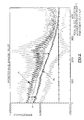
- Figure 2 show positioning error plots for a typical single axis CNC tool drive assembly.
- the abscissa is the tool slide position as indicated by the output of an encoder associated with the slide drive screw, and the ordinate is the error figure which would have to be summed with the tool slide position as indicated by the encoder to produce the corrected tool slide position.
- the plots were produced by using a standard laser measuring system, a Hewlett Packard laser interferometer unit, to give a precise reading of the tool position corresponding to the shaft encoder output.
- An HP85 personal computer is used to collect and analyse the calibration data, and to calculate the compensation values, which are then "down loaded" into the memory device of the compensation system.
- a Renishaw laser system with an Amstrad 1640 or Compaq personal computer may alternatively be used to provide increased storage of compensation points.
- plots A are five superimposed plots corresponding to the forward movement of the tool slide
- plots B are five superimposed plots corresponding to reverse movement of the tool slide.
- the vertical amount Y between the plots A and B corresponds to the backlash in the tool drive assembly, and this amount can be seen to vary with the tool slide position.
- the undulations in plots A and B represent cyclic errors, and it can be seen that the cyclic errors are generally larger in the plots A for forward movement than for the reverse slide movement of plots B.
- the five plots A do not coincide precisely due to random errors.
- the EPROM which is programmed with the error readings from Figure 2 and then inserted into compensator 16 stores an average value corresponding to the five curves A for each shaft encoder output together with a further set of average values corresponding to the three curves B.
- the use of the summation unit 14 at the output of the controller 5 means that the compensation procedure need not interfere with the controller hardware or the operation of the controller 5, and in particular no demands are made on the memory of the controller.
- the interface hardware can be tailored to suit a wide range of NC servo systems the error compensation system described can be readily adapted to suit different machines, without modification of the NC controller.
- the processing circuit 16 is preferably configured to enable the edges of the usual dual-pulse signal from the encoder 9 to be counted rather than the complete "double-pulses" so as to increase the positioning accuracy, and this switching facility can be linked, if desired, to a resolution-change switch on the CNC controller.
- the microprocessor contained in compensator 17 be arranged to run at a frequency greater than the maximum frequency of encoder pulses (typically > 100KHz). This is particularly desirable for a multi-axis machine where a complex volumetric compensation algorithm is used to take account of the multi-axis error components. It is an advantage of performing the calculation of the compensation signal external to the CNC controller that the frequency of the CNC microprocessor does not limit the calculating ability of the overall system. Even if the CNC microprocessor operated at a comparable frequency it would probably not be performing error updates continuously due to the other functions of the CNC controller that it has to perform, so that error updates would be infrequent.
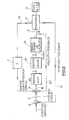
- Figure 3 shows the invention applied to a (single axis) NC machine tool in which the tool slide 2 is driven by an electro-hydraulic servo motor assembly comprising a servo valve 20 and a servo motor or cylinder 21.
- an electro-hydraulic servo motor assembly comprising a servo valve 20 and a servo motor or cylinder 21.
- the unit 21 is a servo cylinder then it may not be possible to obtain a velocity feedback signal 10′, so that in some applications of the invention velocity feedback may be absent.
Landscapes
- Engineering & Computer Science (AREA)
- Human Computer Interaction (AREA)
- Manufacturing & Machinery (AREA)
- Physics & Mathematics (AREA)
- General Physics & Mathematics (AREA)
- Automation & Control Theory (AREA)
- Automatic Control Of Machine Tools (AREA)
- Control Of Position Or Direction (AREA)
- Numerical Control (AREA)
Abstract
In order to compensate for errors in the positioning of a tool by a servo motor (4) resulting from mechanical inaccuracies in the machine tool slides (2) and drive (3), an analogue error compensation signal (12) is generated by a compensation unit (1) in which is stored calibration data relating to the components of the positioning error. The error compensation signal (12) is summed by a summation unit (14) with the uncompensated analogue position error signal (7) generated at the output of a CNC controller (5), and the resulting signal (15), as modified by the usual velocity feedback signal 10′ from the servo motor (4), is used to drive the servo motor (4). The resolution of the error compensation signal (12) is arranged to be greater than that of the position error signal (7), which is generally limited by the number of bits of the digital to analogue converter in the output stage of the controller (5). As the demand position is closely approached the servo (4) is driven substantially by the error compensation signal (12).
Description
- This invention relates to error compensation systems for correcting or reducing positioning errors which arise when a movable body is positioned along a control axis by a servo motor/actuator means and particularly, but not exclusively, to machine tool error compensation systems for correcting or reducing positioning errors associated with the control of the tool position.
- Such systems have been discribed for example in British Patent Specfication GB 1 142 774 and European Patent Specification EP 0 049 153 A.
- This invention relates more particularly, but not exclusively, to a numerically controlled machine tool of the kind comprising a tool holder driven by a tool drive, a tool positioning servo motor/actuator operating the tool drive and controlled in response to an analogue position error signal, a position transducer responsive to the position of the tool, tool holder or tool drive to provide a position feedback signal, and a numerically controlled controller responsive to a position demand signal and to the position feedback signal to produce the analogue position error signal. Such a machine tool will hereinafter be referred to as a "machine tool of the kind set forth".
- The servo motor/actuator can be an electric servo motor or an electro-hydraulic servo motor/actuator.
- In a machine tool of the kind set forth it is generally desirable to provide a velocity feedback loop. A velocity transducer is arranged to be responsive to the velocity of the tool drive or associated component to provide a velocity feedback signal, and a summation means is provided for combining the analogue position error signal with the velocity feedback signal to produce an analogue servo drive signal which is applied to the servo motor/actuator.
- That type of feedback control is known in servo mechanism theory as "cascade control" or "minor-loop feedback" (see "Control System Principles and Design" by Ernest O. Doebelin, John Wiley & Sons 1985 page 13). As applied to a machine of the kind set forth the controller employs digital computing with a DAC (digital to analogue converter) at its output, whereas analogue methods are used in the dynamic control and stabilisation of the servo loops themselves.
- However, in some machines of the kind set forth, and to which the invention can apply, there is no velocity feedback loop, but instead the position loop is of high gain.
- The position transducer may be a digital transducer (encoder) or an analogue transducer (synchro, resolver etc.)
- The accuracy of a machine tool is a limiting factor in the accuracy of finished parts machined by the machine tool. Errors in the motion of the tool itself produce an identical error in the finished part. Although designers of machine tools generally aim to minimise the errors in the movement of the tool by tackling the causes of such errors, this approach is extremely expensive, particularly when a very high accuracy is required. Also, that approach cannot generally be used to improve the accuracy of an existing machine without substantial rebuilding of the machine tool.
- Some current high cost CNC machine controllers provide a degree of attempted compensation for errors in the mechanical movement of the tool. However, the compensation system employed generally involves measuring the tool positioning error at only a limited number of tool slide positions on a single axis, and those point errors are then used by the CNC controller to correct internally of the controller the computation of the position error signal applied to the tool positioning servo associated with that tool slide. No attempt is made in such systems to interpolate between or extrapolate from the point errors, each error value (converted into units of servo counts) is simply added to the "following error" as the slide physically passes the corresponding correction point during the execution of the programmed axis move or job operation. Thus, an error value is employed without modification until the next correction point is reached, whereupon the new error measurement is used until a subsequent correction point is reached. It will be appreciated that this method does not produce accurate error compensation for tool slide positions intermediate to the correction points.
- As is known by those skilled in the art, the "following error" is the lag of the actual tool or tool slide position (depending upon the point of measurement by the position transducer i.e. whether the transducer is associated with the tool or with the tool slide respectively) from the demand position at any instant of time (and is proportional to the velocity of axis motion). The position demand signal is incrementally summed with the position feedback signal to produce the following error. The following error is then used to produce the position error signal to drive the axis servo in the next servo cycle, the change from a following error signal to a position error signal involving a change of units.
- With such known high cost CNC controllers the output of the controller is an analogue position error signal which is applied to the input of the servo (in conjunction with a velocity feedback signal). The output stage of such a controller is a DAC typically with a resolution of no more than 12 bits. We have realised that any correction signal which is applied in the control system at a position prior to that digital to analogue converter will inevitably be restricted in its accuracy by the resolution of the 12 bit converter. We shall now demonstrate the restriction involved.
- The maximum traverse rate of a high cost servo system is, say, 5000 mm/min. Such a servo has, typically, a position loop gain of 1800 mm/min/mm. This provides a maximum (steady state) following error of 5000/1800 = 2.78 mm.
- The digital to analogue converter typically has a 10 volt output range and, to take account of the transient situation, the digital to analogue scaling would be 10 volts output for 2 X 2.78 mm = 5.56 mm. Since the resolution is limited to 12 bits (with 1 bit used for direction) then the best resolution achievable is 5.56/2048 = 0.0027 mm.
- Therefore, no matter what refinements are included in the CNC controller to take account of tool positioning errors by way of the injection of an error compensation signal into the control system of the CNC controller itself, the resolution achievable can never be better than that determined by the digital to analogue converter, 0.0027 mm in the example.
- This factor appears not to have been appreciated by the devisers of previous proposals for error compensation who have concentrated on implementing an error compensation within the CNC controller. An additional disadvantage of such proposals was that they sometimes utilised some of the restricted memory capacity of the CNC controller. This can mean that the functions of the CNC controller are restricted in other respects.
- A general disadvantage of the previous proposals is that if they were to be applied to a CNC controller having no error compensation facility as manufactured, the internal circuitry or software of the controller required alteration. Whilst it may sometimes be economic to carry out such a modification when supplying new CNC machines, it would not generally be economic to modify old machines.
- We have taken a broad look at the various errors which arise in the positioning of the tool relative to the workpiece with the aim of devising systems which, so far as possible, compensate for the mechanical errors in such positioning by the calculation of an error compensation signal which is used to adjust the tool drive signal applied to the input of the servo system associated with the tool movement.
- A first aspect of the present invention is based on our idea of generating an analogue error compensation signal which is used to modify the analogue servo drive signal. Thus, we combine a correction signal with the (uncorrected) analogue position error signal generated by the (uncompensated) CNC controller, or with the velocity feedback signal.
- We have set out to provide an error compensation unit which has its own memory such that the unit can be used, if desired, with existing machine tools to improve their accuracy whilst not affecting their functions in other ways.
- Thus, one application of our invention is to existing machine tools where our compensation unit can be provided without any modifications being made to the CNC controller or to the tool slide servo system.
- According to the first aspect of the present invention we provide a method of compensating for the effect of positioning errors in the positioning of a movable body in a body positioning apparatus of the kind comprising a body drive for positioning the body along a control axis, a body positioning servo motor/actuator means operating the body drive and controlled in response to an analogue position error signal, a position transducer responsive to the position of the body, body holder or body drive, and a digital controller responsive to a position demand signal and to the position feedback signal to produce, through a digital to analogue convertor, the analogue position error signal, characterised in that the method comprises monitoring the output of the position transducer and computing or selecting an analogue error compensation amount for the body position on the basis of stored calibration data corresponding to the position transducer output, and using the analogue error compensation amount to modify the servo drive signal.
- According to a second aspect of the invention we provide a body positioning apparatus of the kind comprising a body carrier driven by a body drive for positioning the body along a control axis, a body positioning servo motor actuator means operating the body drive and controlled in response to an analogue position error signal, a position transducer responsive to the position of the body, body carrier or body drive, to provide a position feedback signal, and a digital controller having a digital to analogue convertor at its output, the controller being responsive to a position demand signal and to the position feedback signal to produce the analogue position error signal, the apparatus further comprising an error compensation means for compensating for or reducing the effect of repeatable errors in the positioning of the body, the error compensation means providing a correction or adjustment signal for modifying the control of the body position, characterised in that the error compensation means comprises a store of calibration data corresponding to the position transducer output, and the error compensation means provides an analogue error compensation amount which is summed with the analogue position error signal in producing the drive signal which is applied to the servo means.
- When in a machine tool control system the machine tool is provided with a velocity feedback loop, the servo drive signal being produced by summing the analogue position error signal with the velocity feedback signal, the compensation amount may, of course, be summed either with the position error signal or with the velocity feedback signal prior to summing of those signals, provided of course that the correct positive or negative sense is chosen.
- Thus, in effect, we permit the controller to compute the analogue position error signal from the unmodified position transducer signal and position demand signal, and then we apply a correction to that position error signal.
- A significant advantage of making the compensation by modifying the analogue drive applied to the servo motor/actuator is that this can be done entirely independently of the controller operation itself which means that an existing or conventional controller can be employed, and no additional demand is made on the memory of the controller. Thus the error compensation signal can be generated in an independent error compensation unit the output of which can readily be interfaced with the controller output. Such a unit can readily be applied to an existing or new machine tool to improve substantially the tool positioning accuracy.
- According to a third aspect of the invention we provide a positioning error correction unit adapted to be connected to a body positioning apparatus, the body positioning apparatus being of the kind comprising a body carries driven by a body drive for positioning the body along a control axis, a body positioning servo motor/actuator means operating the body drive means and controlled in response to an analogue position error signal, a position transducer responsive to the position of the body, body carrier or body drive, to provide a position feedback signal, and a digital controller having a first digital to analogue convertor at its output, the controller being responsive to a position demand signal and to the position feedback signal to produce the analogue position error signal characterised in that the positioning error correction unit comprises an input for connection to the position transducer, a store for calibration data corresponding to the position transducer output, a digital processer for accessing the calibration data, and a second digital to analogue converter for providing an analogue output signal at an output connection of the unit, the output connection being adapted to be connected to a summation means arranged to sum the outputs from the first and second digital to analogue converters.
- The controller is preferably a CNC (computer numerically controlled controller) but it could be a basic NC controller.
- A scaling factor or ratio is preferably provided between the units of the analogue error compensation signal and the units of the analogue position error signal. That is, for a given following error amount and equal compensation error amount, the analogue position error signal (corresponding to the following error) is arranged to be greater than the corresponding error compensation signal by a scaling factor f which is greater than unity.
- The scaling factor f is preferably greater than two.
- Most preferably the scaling factor f is greater than four.
- The scaling factor f is preferably an integer.
- This scaling factor provides a ratio between the resolution of the analogue error compensation signal and the resolution of the position error signal in favour of the error compensation signal.
- For small error amounts, when the tool is closely approaching the demand position, the analogue error compensation signal (of high resolution) will dominate the position error signal (of lower resolution) and accordingly a high degree of accuracy of tool position can be achieved, despite the fact that a "low" resolution NC controller is employed. As the tool closely approaches the commanded position the stepped output of the digital to analogue converter of the controller will enter the zero deadband, but the error compensation signal will provide the small servo drive signal required to drive the tool to the demand position.
- Our studies of the tool positioning errors of uncompensated machine tools show various error components:-
- 1) linear positioning error - these are non-periodic progressive errors associated with the linear displacement of an axis. It is the main type of error which existing commercially applied error compensation systems attempt to deal with.
- 2) cyclic errors - these are periodic errors largely due to eccentric components in the lead screw thread
- 3) backlash/hysteresis in the tool drive, which we find in general varies with the tool position
- 4) thermal fluctuations causing deformation of the machine tool structure, such as spindle thermal growth
- 5) multiple axis effects - when, as usual, the tool position is determined by two or more slides, displacement on one axis is influenced by displacements on the other axis. These errors are produced by geometrical inaccuracies in the machine tool structure.
- 6) deflection errors produced by machining loads
- The stored calibration data can include sets of reference values which correspond to some of the above error sources. Of course,
items 4 and 6 would involve the use of additional transducers to measure temperature, and machine load respectively. - The stored data is preferably in the form of a look-up table which is conveniently held in a programmable memory, such as an E-PROM.
- The data is loaded into the programmable memory in a calibration procedure during which the precise position of the tool and the angular and straightness errors relative to the machine bed measured, conveniently by a laser interferometer, and the corresponding output signal of the position transducer/s is recorded.
- We consider that it may be inventive in itself to isolate and use some of the foregoing error components as the basis for computing/selecting an error compensation signal. Whilst we prefer that the error compensation signal is then utilised in a manner which is in accordance with the first aspect of the invention, we do not wish to preclude the possibility that the error compensation signal may be used in other ways.
- We consider that it is almost essential to deal with the multiple axis effects (5) mentioned above since any attempt to correct accurately for some or all of the single axis errors (1), (2), (3), (4), (6) above would be undermined by the errors produced by the generally substantial amounts of the multiple axis effects.
- The multiple axis effects can conveniently be resolved, by conventional metrological analysis, into the following tool position error components:-
- a) three angular errors-pitch, yaw and roll associated with each axis.
- b) three translatory errors-comprising of the positioning error associated with the desired direction of axis motion plus two straightness errors associated with motion in the directions perpendicular to the desired direction of axis motion.
These translatory errors together with the three angular errors provide six error components for each axis. - c) non-orthogonality errors, due to the out-of-squareness between the directions of the tool slide axes. This is simply the angular relationship between the xy, yz and xz planes of a three axis machine, giving three error figures.
- For a 3-axis machine the error components (a) and (b) give 18 components in all, with (c) giving 3 components, to provide a total of 21 error components. Some of these may be irrelevant in practice depending upon their magnitude and the mechanical configuration of the machine.
- If the machine further has rotational axes, further error components need to be considered for measurement and use in constructing an error compensation vector to be combined with the position error vector generated by the (uncompensated) CNC controller.
- In order to measure the various error components in a three axis machine it is necessary to set up respective tool position measuring devices, such as laser measuring devices (but for roll a precise electronic level is employed), for each axis, and then to measure and record the magnitude of the relevant error components (both angular and translatory) along the full length of travel of each axis starting from a datum position common to all axes.
- A separate measurement procedure is required to obtain the non-orthogonality figures (three angles).
- The values of all the relevant error components for each axis are incorporated in look up tables, which may then be used to calculate the positioning error value at the tool point for any position in the working area or volume.
- The following aspect of the invention is concerned with correcting for error component (5) listed above in a machine having at least two axes.
- According to a fourth aspect of the invention an error compensation system for a numerically controlled machine tool comprises a programmable memory which has been loaded during a calibration procedure with a set of look up tables comprising (a) a set of relatively accurate measurements (or error components) for the tool position along a first axis each corresponding to (b) tool position transducer output values from a first transducer responsive to tool/tool holder/tool drive position on the first axis of movement (c) a set of error components for tool position along the first axis corresponding to (d) second tool position transducer output values from a second transducer responsive to tool/tool holder/tool drive position on a second axis of movement, the system including means adapted in use of the machine tool to take a value from the set (a) based on a measurement by the first transducer of the first axis position of the tool, and to modify that amount by taking an amount from set (c) corresponding to the measurement by the second transducer of the second axis position of the tool, the modified amount thus produced being used as the basis of an error compensation on control of the tool position along the first axis.
- An adaptive compensation algorithm is used to combine the various error components, which for a machine having several axes is a complex task.
- It will be appreciated that such a system would be capable of providing an accurate value for the precise position of the tool along the first axis irrespective of the position of the tool along the second axis, assuming that error component (5) was the sole error.
- If it is also important to obtain precise positioning of the tool along the second axis then further look-up tables will need to be incorporated in the programmable memory to enable the computation of a corrected value or error for the tool position along the second axis for a particular combination of readings of the first and second transducers encountered in use.
- According to a fifth aspect of the invention the look-up table/s produced in calibrating the tool slide/s can be used to correct the readings provided by the tool position transducers when the tool is replaced by a probe for checking the accuracy of a machined component.
- Some embodiments of the invention will now be further described, by way of example only, with reference to the accompanying drawings in which:-
- Figure 1 is a block diagram of an error compensation system connected to a single axis CNC machine;
- Figure 2 shows plots of errors in tool position, as measured with a laser interferometer, against the tool position indicated by an encoder; and
- Figure 3 is a block diagram similar to Figure 1 but showing the invention applied to a NC machine with an electro-hydraulic servo motor.
- Figure 1 shows the application of an error compensation unit 1 to an existing CNC machine comprising a
tool slide 2,tool slide drive 3, drive motor 4 for thetool slide 2 and anuncompensated CNC controller 5, adrive amplifier 6 being positioned between theposition error output 7 of thecontroller 5 and thecontrol input 8 of the slide drive motor 4. An optical encoder 9 is associated with the spindle of theslide drive 3 to provide pulse signals corresponding to the degree of rotation of the slide drive from a datum. In the unmodified condition of the CNC machine the optical encoder 9 is used merely to provide a position feedback signal online 10 to theposition feedback input 11 of thecontroller 5. Within the controller 5 a position demand signal is generated in response to a programmed set of machining instructions appropriate to the particular machining operation to be performed, and a following error is computed, simply by taking the difference between the position demand signal and the position feedback signal. - The encoder 9 may alternatively be replaced by a transducer responsive to the tool slide or tool position. Instead of an optical encoder 9, an analogue transducer (synchro or resolver) could be employed in conjunction with an analogue to digital converter (ADC), which may be external to or incorporated in the
controller 5. - In accordance with certain aspects of the invention the compensation unit provides an analogue compensation signal on
line 12 in response to position feedback information provided online 13 from the optical encoder 9. The uncompensated analogue position error signal at theoutput 7 ofcontroller 5 is modified in response to the analogue compensation signal online 12 in thesummation unit 14, which also incorporates thevelocity feedback signal 10′ from a tachometer or resolver incorporated in motor 4, to provide a compensated servo drive signal online 15 to control the drive motor 4. - The servo drive signal on
line 15 is a velocity error signal, and the use of the position error signal online 7 as the velocity demand signal applied to the velocity servo loop is known as "cascade control". - The compensation unit 1 essentially comprises an encoder
signal processing circuit 16 adapted to convert the dual pulse output signals online 13 into an uncorrected position signal, a microprocessor basedcompensator 17 which computes a positioning error amount from the uncorrected position signal by utilising a look-up table stored in an EPROM, and ananalogue interface circuit 18 which converts the error amount into the analogue error compensation signal online 12. It will be appreciated that, for a notional single axis machine, the EPROM stores a set of positioning error values corresponding to unique position measurements indicated by the optical encoder. The positioning error values are based on pre-recorded accurate measurements of the tool position (as previously measured with a laser interferometer). - It should be appreciated that Figure 1 is a block diagram only and that there are several ways in which the invention could be implemented in accordance with the block diagram.
- In particular there are various ways in which the three
signals summation unit 14 could be a pre-amplifier for the DC motor 4. - Alternatively the
velocity feedback signal 10′ could first be summed with the compensation signal (thevelocity feedback signal 10′ being of course negative feedback) in a servo comparator, and then the output of that unit could be summed with theposition error signal 7 in a pre-amplifier which provides thesignal 15 to themain drive amplifier 6. - Another possibility would be first to combine the (uncompensated)
position error signal 7 with thecompensation signal 12 to provide a compensated position error signal which is then summed in a motor pre-amplifier with thevelocity feedback signal 10′, to provide thesignal 15 to themain drive amplifier 6. The summation of the uncompensatedposition error signal 7 with thecompensation signal 12 can be performed in a suitable amplifier external to thecontroller 5. However, it would be possible in some cases to carry out the summation in the DAC output stage of thecontroller 5 if desired. - An important advantage gained by generating and utilising the
error compensation signal 12 external to thecontroller 5 is that the resolution of the error compensation signal can be determined independently of the resolution associated with theposition error output 7 of thecontroller 5. For example, the DAC in the output stage of thecontroller 5 typically provides ±10 volts output corresponding to 12 bits input, whereas typically the DAC incorporated in theinterface hardware 18 can be arranged to provide ±2.5 volts output for 12 bits input. This means that the resolution of the compensation signal is four times that of theposition error signal 7, and this scaling factor could be further increased if desired by reducing further the voltage range of the DAC inelement 18. - It will be appreciated that when the
position error signal 7 is large, because the tool is well away from the demanded tool position (the position demand signal generated by the programme for controller 5), theerror compensation signal 12 will be relatively small compared with theposition error signal 7, and the servo motor 4 will be driven substantially in response to thesignal 7. However, when the tool is approaching the demanded position, then theposition error signal 7 will be relatively small, and theerror compensation signal 12 will predominate in determining thevelocity error signal 15 driving the servo motor 4. Furthermore, when the demanded position is closely approached the steppedoutput 7 of the controller will enter the zero deadband, and final positioning is determined entirely by theerror compensation signal 12. - Thus, the scaling factor (four in the foregoing example) between the analogue output ranges of the DAC's associated respectively with the outputs of the
controller 5 andinterface hardware 18 enables a substantially improved compensation for tool positioning errors to be achieved compared with what would be achievable by combining a compensation signal with the following error incontroller 5. - It is preferred that the scaling factor is an integer, otherwise a sufficiently large position error signal might be generated, in response to the control exerted by the error compensation signal, to take the output of the controller out of the deadband again.
- What is shown in Figure 1 is merely a basic system in which it is assumed that there is only one axis of tool movement (one tool slide), and that there is a 1:1 correspondence between the optical encoder readings and the previously recorded accurate tool position values. In practice, as indicated previously, there are several other factors which are preferably taken into account and which necessitate a more complex set of look-up tables of error components to be stored in the EPROM. The compensator (17) will then combine the appropriate error components in order to compute a single error figure for each axis, thereby to provide an analogue compensation vector on
line 12. - Figure 2 show positioning error plots for a typical single axis CNC tool drive assembly. The abscissa is the tool slide position as indicated by the output of an encoder associated with the slide drive screw, and the ordinate is the error figure which would have to be summed with the tool slide position as indicated by the encoder to produce the corrected tool slide position. The plots were produced by using a standard laser measuring system, a Hewlett Packard laser interferometer unit, to give a precise reading of the tool position corresponding to the shaft encoder output. An HP85 personal computer is used to collect and analyse the calibration data, and to calculate the compensation values, which are then "down loaded" into the memory device of the compensation system. A Renishaw laser system with an Amstrad 1640 or Compaq personal computer may alternatively be used to provide increased storage of compensation points.
- In Figure 2 plots A are five superimposed plots corresponding to the forward movement of the tool slide, and plots B are five superimposed plots corresponding to reverse movement of the tool slide. The vertical amount Y between the plots A and B corresponds to the backlash in the tool drive assembly, and this amount can be seen to vary with the tool slide position. The undulations in plots A and B represent cyclic errors, and it can be seen that the cyclic errors are generally larger in the plots A for forward movement than for the reverse slide movement of plots B. The five plots A do not coincide precisely due to random errors.
- The EPROM which is programmed with the error readings from Figure 2 and then inserted into
compensator 16 stores an average value corresponding to the five curves A for each shaft encoder output together with a further set of average values corresponding to the three curves B. - It will be appreciated that the use of the
summation unit 14 at the output of thecontroller 5 means that the compensation procedure need not interfere with the controller hardware or the operation of thecontroller 5, and in particular no demands are made on the memory of the controller. - Since the interface hardware can be tailored to suit a wide range of NC servo systems the error compensation system described can be readily adapted to suit different machines, without modification of the NC controller.
- The
processing circuit 16 is preferably configured to enable the edges of the usual dual-pulse signal from the encoder 9 to be counted rather than the complete "double-pulses" so as to increase the positioning accuracy, and this switching facility can be linked, if desired, to a resolution-change switch on the CNC controller. - Since the size of the memory associated with
compensator 17 can be chosen at will, there is no effective limit to the number of compensation points that can be provided for each axis. - In order to utilise fully the information provided by the tool position encoder pulses it is desirable that the microprocessor contained in
compensator 17 be arranged to run at a frequency greater than the maximum frequency of encoder pulses (typically > 100KHz). This is particularly desirable for a multi-axis machine where a complex volumetric compensation algorithm is used to take account of the multi-axis error components. It is an advantage of performing the calculation of the compensation signal external to the CNC controller that the frequency of the CNC microprocessor does not limit the calculating ability of the overall system. Even if the CNC microprocessor operated at a comparable frequency it would probably not be performing error updates continuously due to the other functions of the CNC controller that it has to perform, so that error updates would be infrequent. - Figure 3 shows the invention applied to a (single axis) NC machine tool in which the
tool slide 2 is driven by an electro-hydraulic servo motor assembly comprising aservo valve 20 and a servo motor orcylinder 21. When theunit 21 is a servo cylinder then it may not be possible to obtain avelocity feedback signal 10′, so that in some applications of the invention velocity feedback may be absent. - Although the invention has been described as applied to a machine tool, it should be appreciated that it is applicable to other devices, such as a plotter, in which a movable body is positioned along at least one control axis by a servo means in response to a position demand.
Claims (12)
1. A method of compensating for the effect of positioning errors in the positioning of a movable body in a body positioning apparatus of the kind comprising a body drive (3) for positioning the body (2) along a control axis, a body positioning servo motor/actuator means (4) operating the body drive (3) and controlled in response to an analogue position error signal (7), a position transducer (9) responsive to the position of the body, body holder or body drive, and a digital controller (5) responsive to a position demand signal and to the position feedback signal (10) to produce, through a digital to analogue convertor, the analogue position error signal (7), characterised in that the method comprises monitoring the output (13) of the position transducer (9) and computing or selecting an analogue error compensation amount (12) for the body position on the basis of stored calibration data (in 17) corresponding to the position transducer output (13), and using the analogue error compensation amount (12) to modify the servo drive signal (15).
2. A method as claimed in claim 1 characterised in that the analogue error compensation amount (12) is summed (at 14) with the analogue error signal (7) produced by the controller, to produce a modified servo drive signal (15).
3. A method as claimed in claim 1 or claim 2 characterised in that a scaling factor (f) greater than unity is provided between the units of the analogue position error signal (7) produced by the controller and the units of the analogue error compensation signal (12).
4. A method as claimed in any of the preceding claims characterised in that the body positioning apparatus is a machine tool positioning apparatus.
5. A body positioning apparatus of the kind comprising a body carrier driven by a body drive for positioning the body along a control axis, a body positioning servo motor 1 actuator means (4) operating the body drive (3) and controlled in response to an analogue position error signal (7), a position transducer responsive to the position of the body, body carrier or body drive (3), to provide a position feedback signal (10), and a digital controller (5) having a digital to analogue convertor at its output, the controller (5) being responsive to a position demand signal and to the position feedback signal (10) to produce the analogue position error signal (7), the apparatus further comprising an error compensation means (1) for compensating for or reducing the effect of repeatable errors in the positioning of the body, the error compensation means (1) providing a correction or adjustment signal (12) for modifying the control of the body position, characterised in that the error compensation means (1) comprises a store (17) of calibration data corresponding to the position transducer output (13), and the error compensation means (1) provides an analogue error compensation amount (12) which is summed (at 14) with the analogue position error signal (7) in producing the drive signal (15) which is applied to the servo means (4).
6. A body positioning apparatus as claimed in claim 5 characterised in that the error compensation means (1) comprises a digital processor (17) and a second digital to analogue converter for providing the analogue error compensation amount (12), a scaling factor (f) greater than unity being provided between the units of the analogue position error signal (7), that analogue signal produced by the controller from a digital following error signal, and the units of the analogue error compensation signal (12), that is for a given digital amount of the digital following error signal the corresponding analogue position error signal which would be generated by the first digital to analogue converter of the controller is greater by the factor (f) than that analogue error compensation signal (12) which would be generated by the second digital to analogue converter from a digital compensation signal of equal digital amount to said following error signal.
7. A numerically controlled machine tool of the kind comprising a tool holder driven by a tool drive (3), a tool positioning servo motor/actuator (4) operating the tool drive (3) and controlled in response to an analogue position error signal (7), a position transducer (9) responsive to the position of the tool, tool holder or tool drive (2) to provide a position feedback signal (10), and a numerically controlled controller (5) responsive to a position demand signal and to the position feedback signal (10) to produce the analogue position error signal (7), the machine tool further comprising an error compensation means (1) for compensating for or reducing the effect of repeatable errors in the positioning of the tool, the error compensation means (1) providing a correction or adjustment signal (12) for modifying the control of the tool position, characterised in that the error compensation means (1) comprises a store (17) of calibration data corresponding to the position transducer output (13), and the error compensation means (1) provides an analogue error compensation amount (12) which is summed (in unit 14) with the analogue position error signal (7) in producing the drive signal (15) which is applied to the servo motor/actuator (4).
8. A machine tool as claimed in Claim 7 including the feature (known in itself) that a velocity feedback signal (10′) is also summed with the position error signal (7) in producing the servo drive signal (15).
9. A machine tool as claimed in Claim 7 or Claim 8 in which a scaling factor (f) greater than unity is provided between the units of the analogue position error signal (7) (the analogue signal produced from a digital following error) and the units of the analogue error compensation signal (12), that is for a given digital amount of the digital following error signal the corresponding analogue position error signal generated by a first digital to analogue converter is greater by a factor (f) than that analogue error compensation signal (12) which would be generated by a second digital to analogue converter from a digital compensation signal of equal digital amount.
10. A machine tool as claimed in Claim 9 in which the scaling factor (f) is at least four.
11. A machine tool as claimed in any claims 7 to 10 in which the error compensation means (1) comprises a programmable memory (17) which has been loaded during a calibration procedure with a set of look up tables comprising (a) a set of relatively accurate measurements (or error components) for the tool position along a first axis each corresponding to (b) tool position transducer output values from a first transducer responsive to tool/tool holder/tool drive position on the first axis of movement (c) a set of error components for tool position along the first axis corresponding to (d) second tool position transducer output values from a second transducer responsive to tool/tool holder/tool drive position on a second axis of movement, the machine including means adapted in use of the machine tool to take a value from the set (a) based on a measurement by the first transducer of the first axis position of the tool, and to modify that amount by taking an amount from set (c) corresponding to the measurement by the second transducer of the second axis position of the tool, the modified amount thus produced being used to produce the error compensation signal associated with the positioning of the tool along the first axis.
12. A positioning error correction unit (1) adapted to be connected to a body positioning apparatus, the body positioning apparatus being of the kind comprising a body carrier driven by a body drive for positioning the body along a control axis, a body positioning servo motor/actuator means (4) operating the body drive means (3) and controlled in response to an analogue position error signal (7), a position transducer responsive to the position of the body, body carrier or body drive (3), to provide a position feedback signal (10), and a digital controller (5) having a first digital to analogue convertor at its output, the controller (5) being responsive to a position demand signal and to the position feedback signal (10) to produce the analogue position error signal (7) characterised in that the positioning error correction unit comprises an input for connection to the position transducer, a store for calibration data corresponding to the position transducer output, a digital processer for accessing the calibration data, and a second digital to analogue converter for providing an analogue output signal at an output connection of the unit, the output connection being adapted to be connected to a summation means arranged to sum the outputs from the first and second digital to analogue converters.
Applications Claiming Priority (2)
| Application Number | Priority Date | Filing Date | Title |
|---|---|---|---|
| GB8806574 | 1988-03-19 | ||
| GB888806574A GB8806574D0 (en) | 1988-03-19 | 1988-03-19 | Machine tool error compensation systems |
Publications (1)
| Publication Number | Publication Date |
|---|---|
| EP0334541A1 true EP0334541A1 (en) | 1989-09-27 |
Family
ID=10633734
Family Applications (1)
| Application Number | Title | Priority Date | Filing Date |
|---|---|---|---|
| EP89302541A Withdrawn EP0334541A1 (en) | 1988-03-19 | 1989-03-15 | Machine tool error compensation systems and the like |
Country Status (6)
| Country | Link |
|---|---|
| US (1) | US5021941A (en) |
| EP (1) | EP0334541A1 (en) |
| JP (1) | JPH02230303A (en) |
| KR (1) | KR890015099A (en) |
| CN (1) | CN1038359A (en) |
| GB (1) | GB8806574D0 (en) |
Cited By (3)
| Publication number | Priority date | Publication date | Assignee | Title |
|---|---|---|---|---|
| US5975744A (en) * | 1995-07-13 | 1999-11-02 | Renishaw Plc | Real-time compensation system and method |
| EP2372312A1 (en) * | 2010-03-31 | 2011-10-05 | SICK STEGMANN GmbH | Feedback assembly and feedback method for regulating a servomotor |
| US9146279B2 (en) | 2007-12-07 | 2015-09-29 | Alstom Technology Ltd. | Method for detection of interlaminar sheet short circuits in the stator sheet core of electromachines |
Families Citing this family (51)
| Publication number | Priority date | Publication date | Assignee | Title |
|---|---|---|---|---|
| GB2217051B (en) * | 1988-04-07 | 1992-12-09 | Sony Corp | A servo system for a motor |
| US5223775A (en) * | 1991-10-28 | 1993-06-29 | Eml Research, Inc. | Apparatus and related method to compensate for torque ripple in a permanent magnet electric motor |
| US5492440A (en) * | 1993-05-18 | 1996-02-20 | U.S. Philips Corporation | Apparatus for movement of an object |
| JPH07281723A (en) * | 1994-04-15 | 1995-10-27 | Kitamura Mach Co Ltd | Numerically controlled machine tool |
| US5532922A (en) * | 1994-09-30 | 1996-07-02 | Honeywell Inc. | Non-linear control system for a single input single output process |
| JP5041616B2 (en) * | 1996-06-06 | 2012-10-03 | ザ・ボーイング・カンパニー | Methods for increasing machine accuracy |
| WO1998019824A1 (en) * | 1996-11-07 | 1998-05-14 | Okuma Corporation | Error correction apparatus for nc machine tool |
| DE19708894C2 (en) * | 1997-03-05 | 2003-04-30 | Pfauter Hermann Gmbh Co | Method for position and / or speed control of axes on a machine tool and device for carrying out such a method |
| JP3453043B2 (en) * | 1997-04-30 | 2003-10-06 | 東芝機械株式会社 | Numerical control device for swing mechanism |
| US5949685A (en) * | 1997-06-03 | 1999-09-07 | The Boeing Company | Real-time orientation of machine media to improve machine accuracy |
| US6477433B1 (en) * | 1998-06-04 | 2002-11-05 | Honeywell International Inc. | Control of velocity limited systems |
| US6064170A (en) * | 1998-08-31 | 2000-05-16 | Eastman Kodak Company | Method of controlling a printhead movement based on a screw pitch to minimize swath-to-swath error in an image processing apparatus |
| US6060854A (en) * | 1998-11-12 | 2000-05-09 | Vickers, Inc. | Method and apparatus for compensating for windup in a machine |
| US6653829B1 (en) | 1999-09-17 | 2003-11-25 | Delphi Technologies, Inc. | Low cost approach to measuring high resolution rotary position of electric machines |
| US6648568B2 (en) * | 2001-01-18 | 2003-11-18 | Utica Enterprises, Inc. | Linear blind broaching machine |
| JP4459463B2 (en) * | 2001-02-19 | 2010-04-28 | 株式会社ハーモニック・ドライブ・システムズ | Actuator positioning error correction method |
| US6826499B2 (en) * | 2001-10-01 | 2004-11-30 | Delphi Technologies, Inc. | Method and apparatus for calibrating and initializing an electronically commutated motor |
| JP2003200332A (en) * | 2001-12-27 | 2003-07-15 | Fanuc Ltd | Control device for gear machining |
| US6683461B2 (en) | 2002-03-12 | 2004-01-27 | Itt Manufacturing Enterprises Inc. | Servo controlled calibration of repeatable errors in position transducers |
| JP4115925B2 (en) * | 2003-11-28 | 2008-07-09 | ヤマザキマザック株式会社 | Machine tool control method and control device therefor |
| US7342664B1 (en) | 2004-05-06 | 2008-03-11 | Juliusz George Radziszewski | Scanning double-beam interferometer |
| US7541766B1 (en) * | 2004-06-01 | 2009-06-02 | Sato Jeffrey S | System and method for the intelligent use of software deadband control in a control system |
| US7090561B2 (en) * | 2004-12-07 | 2006-08-15 | General Electric Company | Method and apparatus for pivot point determination and machine tool adjustment |
| JP5091164B2 (en) * | 2006-02-10 | 2012-12-05 | クリンゲルンベルク・ゲゼルシャフト・ミット・ベシュレンクテル・ハフツング | Method for machining bevel gears in the index method to complete the correction of the index error |
| JP4819665B2 (en) * | 2006-12-18 | 2011-11-24 | オークマ株式会社 | Non-circular shape processing equipment |
| WO2010006175A1 (en) * | 2008-07-10 | 2010-01-14 | Applied Magnetics, Llc | Highly precise and low level signal-generating drivers, systems and methods of use |
| US8694133B2 (en) * | 2009-09-05 | 2014-04-08 | M4 Sciences, Llc | Control systems and methods for machining operations |
| EP2319646B1 (en) * | 2009-11-06 | 2012-12-12 | Reika GmbH & Co. KG | Whirling cutting device |
| EP2347846B1 (en) * | 2010-01-20 | 2013-01-09 | Reika GmbH & Co. KG | Circular saw |
| US8631577B2 (en) | 2011-07-22 | 2014-01-21 | Pratt & Whitney Canada Corp. | Method of fabricating integrally bladed rotor and stator vane assembly |
| US8904636B2 (en) | 2011-07-22 | 2014-12-09 | Pratt & Whitney Canada Corp. | Method of fabricating integrally bladed rotor using surface positioning in relation to surface priority |
| US8844132B2 (en) | 2011-07-22 | 2014-09-30 | Pratt & Whitney Canada Corp. | Method of machining using an automatic tool path generator adapted to individual blade surfaces on an integrally bladed rotor |
| US8788083B2 (en) | 2011-07-22 | 2014-07-22 | Pratt & Whitney Canada Corp. | Compensation for process variables in a numerically-controlled machining operation |
| US9003936B2 (en) * | 2011-07-29 | 2015-04-14 | Flow International Corporation | Waterjet cutting system with standoff distance control |
| CN102601728B (en) * | 2012-03-28 | 2014-04-16 | 山东大学 | Automatic compensation method for clamping errors for peripheral grinding of numerically controlled indexable blade |
| CN103776360B (en) * | 2012-10-24 | 2017-06-06 | 绵阳市维博电子有限责任公司 | An automatic cutting machine cutting knife deformation detection device |
| US10245652B2 (en) | 2012-11-05 | 2019-04-02 | M4 Sciences Llc | Rotating tool holder assembly for modulation assisted machining |
| JP5731569B2 (en) * | 2013-05-02 | 2015-06-10 | ファナック株式会社 | Encoder with accuracy correction function |
| WO2015029517A1 (en) * | 2013-08-27 | 2015-03-05 | 三菱重工業株式会社 | Machine tool |
| US9884406B2 (en) | 2014-01-15 | 2018-02-06 | Flow International Corporation | High-pressure waterjet cutting head systems, components and related methods |
| US9590545B2 (en) * | 2014-11-26 | 2017-03-07 | Kohler, Co. | Power angle calculation for alternator controller |
| US10256758B2 (en) | 2014-11-26 | 2019-04-09 | Kohler Co. | Printed circuit board based exciter |
| CN104841988B (en) * | 2014-12-19 | 2017-07-11 | 北汽福田汽车股份有限公司 | Utilize the method for processing parts and part of lathe |
| US10596717B2 (en) | 2015-07-13 | 2020-03-24 | Flow International Corporation | Methods of cutting fiber reinforced polymer composite workpieces with a pure waterjet |
| US10875138B1 (en) | 2016-08-09 | 2020-12-29 | M4 Sciences Llc | Tool holder assembly for machining system |
| CN107508437B (en) * | 2017-08-30 | 2019-04-23 | 中广核核电运营有限公司 | Electricity generator stator core experimental rig and method |
| JP6683749B2 (en) | 2018-03-14 | 2020-04-22 | ファナック株式会社 | Correction amount acquisition device, feed mechanism control device, correction amount acquisition method, and feed mechanism control method |
| GB201813372D0 (en) | 2018-08-16 | 2018-10-03 | Rolls Royce Plc | Machining error compensation |
| JP7348013B2 (en) * | 2019-09-30 | 2023-09-20 | ファナック株式会社 | simulation device |
| CN116736706B (en) * | 2023-06-05 | 2024-03-22 | 中建一局集团第三建筑有限公司 | Synchronous control method of electric lifting sliding mode system based on deviation coupling |
| CN117507469B (en) * | 2024-01-05 | 2024-03-22 | 昆山力比格智能科技有限公司 | Automatic servo operation control method and system for oil press |
Citations (2)
| Publication number | Priority date | Publication date | Assignee | Title |
|---|---|---|---|---|
| EP0049153A2 (en) * | 1980-09-30 | 1982-04-07 | Fanuc Ltd. | Apparatus for correcting positional error. |
| EP0063613A1 (en) * | 1980-10-30 | 1982-11-03 | Fanuc Ltd. | Position error correcting device |
Family Cites Families (8)
| Publication number | Priority date | Publication date | Assignee | Title |
|---|---|---|---|---|
| US3612840A (en) * | 1969-09-08 | 1971-10-12 | Kearney & Trecker Corp | Linear error compensator for numerically controlled machine tools |
| US3917930A (en) * | 1974-11-25 | 1975-11-04 | Cincinnati Milacron Inc | Method and apparatus for adaptively positioning a machine element |
| US4338659A (en) * | 1978-12-15 | 1982-07-06 | Fujitsu Fanuc Ltd. | Position control system for a closed loop type numerical-controlled machine tool |
| US4456863A (en) * | 1980-12-23 | 1984-06-26 | Cleveland Machine Controls, Inc. | Apparatus for automatic calibration of servo response |
| FR2520523A1 (en) * | 1982-01-27 | 1983-07-29 | Commissariat Energie Atomique | ANALOGUE CONTROL STRUCTURE FOR ROTATION POSITION LOOSTS OF A VARIABLE INERTIAL LOADED MOTOR |
| US4446409A (en) * | 1982-03-22 | 1984-05-01 | Lockheed Electronics Co., Inc. | Electronic controller apparatus |
| US4556956A (en) * | 1983-09-16 | 1985-12-03 | General Electric Company | Adjustable gain controller for valve position control loop and method for reducing jitter |
| DE3408551A1 (en) * | 1984-03-08 | 1985-09-12 | Siemens AG, 1000 Berlin und 8000 München | METHOD FOR REDUCING RAILWAY ERRORS IN COMPUTER-CONTROLLED MACHINE TOOLS OR INDUSTRIAL ROBOTS |
-
1988
- 1988-03-19 GB GB888806574A patent/GB8806574D0/en active Pending
-
1989
- 1989-03-14 US US07/323,562 patent/US5021941A/en not_active Expired - Fee Related
- 1989-03-15 EP EP89302541A patent/EP0334541A1/en not_active Withdrawn
- 1989-03-18 CN CN89101528A patent/CN1038359A/en active Pending
- 1989-03-18 KR KR1019890003414A patent/KR890015099A/en not_active Withdrawn
- 1989-03-20 JP JP1069119A patent/JPH02230303A/en active Pending
Patent Citations (2)
| Publication number | Priority date | Publication date | Assignee | Title |
|---|---|---|---|---|
| EP0049153A2 (en) * | 1980-09-30 | 1982-04-07 | Fanuc Ltd. | Apparatus for correcting positional error. |
| EP0063613A1 (en) * | 1980-10-30 | 1982-11-03 | Fanuc Ltd. | Position error correcting device |
Cited By (4)
| Publication number | Priority date | Publication date | Assignee | Title |
|---|---|---|---|---|
| US5975744A (en) * | 1995-07-13 | 1999-11-02 | Renishaw Plc | Real-time compensation system and method |
| US9146279B2 (en) | 2007-12-07 | 2015-09-29 | Alstom Technology Ltd. | Method for detection of interlaminar sheet short circuits in the stator sheet core of electromachines |
| EP2372312A1 (en) * | 2010-03-31 | 2011-10-05 | SICK STEGMANN GmbH | Feedback assembly and feedback method for regulating a servomotor |
| US8510069B2 (en) | 2010-03-31 | 2013-08-13 | Sick Stegmann Gmbh | Feedback apparatus and feedback method for controlling a servomotor |
Also Published As
| Publication number | Publication date |
|---|---|
| GB8806574D0 (en) | 1988-04-20 |
| JPH02230303A (en) | 1990-09-12 |
| US5021941A (en) | 1991-06-04 |
| KR890015099A (en) | 1989-10-28 |
| CN1038359A (en) | 1989-12-27 |
Similar Documents
| Publication | Publication Date | Title |
|---|---|---|
| US5021941A (en) | Position control method and apparatus for a closed loop type numerically controlled machine | |
| CA2704365C (en) | Method and device for preparing error map and numerically controlled machine tool having error map preparation function | |
| US5237509A (en) | Method and apparatus for compensating positional errors | |
| US5408758A (en) | System for compensating spatial errors | |
| JP2510216B2 (en) | Method for calibrating sensors in industrial robots | |
| US6097168A (en) | Position control apparatus and method of the same, numerical control program preparation apparatus and method of the same, and methods of controlling numerical control machine tool | |
| US6252368B1 (en) | Numerically controlled system and backlash compensation device for use with the system | |
| US7571669B2 (en) | Machining apparatus for noncircular shapes | |
| JPH0682302B2 (en) | Method and apparatus for automatically and dynamically adjusting position error | |
| JP4014719B2 (en) | NC machine tool control apparatus and positioning control method | |
| JP2009009274A (en) | Numerical controller | |
| US4879671A (en) | Digital measurement of relative displacement using stored correction address data | |
| US5053973A (en) | Method and apparatus for correcting deflection of a movable member | |
| US5313403A (en) | Numerical control apparatus having a circular interpolation locus display function and control method thereof | |
| US20020121992A1 (en) | Calibrated encoder multiplier | |
| JP2021060673A (en) | Adjustment method allowing for improved accuracy of machine tool | |
| Donmez et al. | A real-time error compensation system for a computerized numerical control turning center | |
| EP0573962B1 (en) | Numerical control device for tool driving along non-orthogonal mechanical axes | |
| CA2717291C (en) | Numerically controlled machine tool and numerical control device | |
| JPH02160457A (en) | Correcting device for straightness of machine tool | |
| JPH1165663A (en) | Position controller and method therefor | |
| EP1092125A1 (en) | Vector measurement for coordinate measuring machine | |
| JPH05169351A (en) | Machine tool thermal displacement compensation method | |
| US5309367A (en) | Pitch error compensating system | |
| JPH0432906A (en) | Pitch error correcting method of multi-axial numerically controlled machine |
Legal Events
| Date | Code | Title | Description |
|---|---|---|---|
| PUAI | Public reference made under article 153(3) epc to a published international application that has entered the european phase |
Free format text: ORIGINAL CODE: 0009012 |
|
| AK | Designated contracting states |
Kind code of ref document: A1 Designated state(s): AT BE CH DE ES FR GB GR IT LI LU NL SE |
|
| 17P | Request for examination filed |
Effective date: 19900302 |
|
| RAP1 | Party data changed (applicant data changed or rights of an application transferred) |
Owner name: ELECTRONIC ACCURACY SYSTEMS LIMITED |
|
| 17Q | First examination report despatched |
Effective date: 19920730 |
|
| STAA | Information on the status of an ep patent application or granted ep patent |
Free format text: STATUS: THE APPLICATION IS DEEMED TO BE WITHDRAWN |
|
| 18D | Application deemed to be withdrawn |
Effective date: 19940322 |