EP0334535A2 - Herstellung eines elektrischen Kabels - Google Patents
Herstellung eines elektrischen Kabels Download PDFInfo
- Publication number
- EP0334535A2 EP0334535A2 EP89302521A EP89302521A EP0334535A2 EP 0334535 A2 EP0334535 A2 EP 0334535A2 EP 89302521 A EP89302521 A EP 89302521A EP 89302521 A EP89302521 A EP 89302521A EP 0334535 A2 EP0334535 A2 EP 0334535A2
- Authority
- EP
- European Patent Office
- Prior art keywords
- mixture
- polyol
- water
- container
- polymeric
- Prior art date
- Legal status (The legal status is an assumption and is not a legal conclusion. Google has not performed a legal analysis and makes no representation as to the accuracy of the status listed.)
- Withdrawn
Links
- 238000004519 manufacturing process Methods 0.000 title claims description 5
- 239000000203 mixture Substances 0.000 claims abstract description 93
- XLYOFNOQVPJJNP-UHFFFAOYSA-N water Substances O XLYOFNOQVPJJNP-UHFFFAOYSA-N 0.000 claims abstract description 63
- 238000009413 insulation Methods 0.000 claims abstract description 44
- 239000004020 conductor Substances 0.000 claims abstract description 30
- 239000007921 spray Substances 0.000 claims description 55
- 229920005862 polyol Polymers 0.000 claims description 43
- 150000003077 polyols Chemical class 0.000 claims description 43
- 238000000034 method Methods 0.000 claims description 27
- 238000012544 monitoring process Methods 0.000 claims description 13
- PEDCQBHIVMGVHV-UHFFFAOYSA-N Glycerine Chemical compound OCC(O)CO PEDCQBHIVMGVHV-UHFFFAOYSA-N 0.000 claims description 12
- 239000004094 surface-active agent Substances 0.000 claims description 12
- 238000005507 spraying Methods 0.000 claims description 10
- 239000000463 material Substances 0.000 claims description 4
- 229920001451 polypropylene glycol Polymers 0.000 claims description 4
- IAYPIBMASNFSPL-UHFFFAOYSA-N Ethylene oxide Chemical compound C1CO1 IAYPIBMASNFSPL-UHFFFAOYSA-N 0.000 claims description 3
- 239000002202 Polyethylene glycol Substances 0.000 claims description 3
- 229920001400 block copolymer Polymers 0.000 claims description 3
- 229920001223 polyethylene glycol Polymers 0.000 claims description 3
- GOOHAUXETOMSMM-UHFFFAOYSA-N Propylene oxide Chemical compound CC1CO1 GOOHAUXETOMSMM-UHFFFAOYSA-N 0.000 claims description 2
- 239000000454 talc Substances 0.000 description 6
- 229910052623 talc Inorganic materials 0.000 description 6
- 238000010276 construction Methods 0.000 description 1
- 239000000428 dust Substances 0.000 description 1
- 239000000383 hazardous chemical Substances 0.000 description 1
- 231100000206 health hazard Toxicity 0.000 description 1
- 238000012423 maintenance Methods 0.000 description 1
- 229920001983 poloxamer Polymers 0.000 description 1
- 238000011144 upstream manufacturing Methods 0.000 description 1
Images
Classifications
-
- B—PERFORMING OPERATIONS; TRANSPORTING
- B05—SPRAYING OR ATOMISING IN GENERAL; APPLYING FLUENT MATERIALS TO SURFACES, IN GENERAL
- B05B—SPRAYING APPARATUS; ATOMISING APPARATUS; NOZZLES
- B05B7/00—Spraying apparatus for discharge of liquids or other fluent materials from two or more sources, e.g. of liquid and air, of powder and gas
- B05B7/24—Spraying apparatus for discharge of liquids or other fluent materials from two or more sources, e.g. of liquid and air, of powder and gas with means, e.g. a container, for supplying liquid or other fluent material to a discharge device
- B05B7/2486—Spraying apparatus for discharge of liquids or other fluent materials from two or more sources, e.g. of liquid and air, of powder and gas with means, e.g. a container, for supplying liquid or other fluent material to a discharge device with means for supplying liquid or other fluent material to several discharge devices
-
- B—PERFORMING OPERATIONS; TRANSPORTING
- B05—SPRAYING OR ATOMISING IN GENERAL; APPLYING FLUENT MATERIALS TO SURFACES, IN GENERAL
- B05B—SPRAYING APPARATUS; ATOMISING APPARATUS; NOZZLES
- B05B14/00—Arrangements for collecting, re-using or eliminating excess spraying material
-
- B—PERFORMING OPERATIONS; TRANSPORTING
- B05—SPRAYING OR ATOMISING IN GENERAL; APPLYING FLUENT MATERIALS TO SURFACES, IN GENERAL
- B05B—SPRAYING APPARATUS; ATOMISING APPARATUS; NOZZLES
- B05B7/00—Spraying apparatus for discharge of liquids or other fluent materials from two or more sources, e.g. of liquid and air, of powder and gas
- B05B7/24—Spraying apparatus for discharge of liquids or other fluent materials from two or more sources, e.g. of liquid and air, of powder and gas with means, e.g. a container, for supplying liquid or other fluent material to a discharge device
- B05B7/2489—Spraying apparatus for discharge of liquids or other fluent materials from two or more sources, e.g. of liquid and air, of powder and gas with means, e.g. a container, for supplying liquid or other fluent material to a discharge device an atomising fluid, e.g. a gas, being supplied to the discharge device
-
- H—ELECTRICITY
- H01—ELECTRIC ELEMENTS
- H01B—CABLES; CONDUCTORS; INSULATORS; SELECTION OF MATERIALS FOR THEIR CONDUCTIVE, INSULATING OR DIELECTRIC PROPERTIES
- H01B13/00—Apparatus or processes specially adapted for manufacturing conductors or cables
- H01B13/06—Insulating conductors or cables
- H01B13/14—Insulating conductors or cables by extrusion
- H01B13/145—Pretreatment or after-treatment
Definitions
- This invention relates to electrical cable manufacture, and more particularly is concerned with a method of manufacturing an electrical cable comprising a polymeric sheath extruded over at least one conductor core provided with polymeric insulation.
- Examples of electrical cables comprising a polymeric sheath extruded over conductor cores provided with polymeric insulation include flat twin core cable utilised in house wiring and appliance leads which may comprise two or three cores.
- the sheath it is desirable for the sheath to be readily strippable from the insulated cores without damaging the insulation in order for connections to be made.
- the insulated cores have been dusted with talc or chalk prior to the extruded sheath being applied over them in order to prevent the sheath adhering to the insulation.
- talc or chalk in this manner gives rise to dust and health hazards.
- the talc or chalk is applied to the insulation by the insulated cores being passed through a bed of the talc or chalk and this has been found to be unreliable since furrowing may occur in the bed so that the whole of the outer periphery of the insulated core does not become covered with the talc or chalk, and blockages in the supply of chalk or talc to the bed also occur. Furthermore, the above-mentioned known operation is not susceptible to use at high throughput speeds, nor is it adaptable for automation.
- an electrical cable comprising a polymeric sheath extruded over at least one conductor core provided with polymeric insulation, said method including applying a polyol-water mixture over the polymeric insulation of the or each conductor core prior to extruding the polymeric sheath thereover such that the polymeric sheath is prevented from adhering to the polymeric insulation.
- the invention includes an electrical cable comprising a polymeric sheath extruded over at least one conductor core provided with polymeric material when made by a method as defined in the last preceding paragraph.
- the invention also includes apparatus for use in a method as defined in the last but one preceding paragraph and comprising at least one spray unit, the or each spray unit having a through-passage for at least one conductor covered with polymeric insulation and provided with spray means arranged for spraying a polyol-water mixture onto the polymeric insulation of the or each conductor during its passage through the spray unit.
- the polyol-water mixture is sprayed onto the polymeric insulation.
- the mixture may comprise from two to six, or preferably three to five parts polyol to one part water by volume. In a preferred embodiment the mixture comprises substantially four parts polyol to one part water by volume.
- a surfactant may be added to the polyol-water mixture prior to the mixture being sprayed onto the polymeric insulation, in which case the mixture may comprise from a half to three parts polyol to one part water by volume, and preferably about one part polyol to one part water.
- the volume of added surfactant may be about 1-2% of the volume of the polyol-water mixture and a suitable surfactant comprises a block copolymer of ethylene oxide and polypropylene oxide.
- the method may include utilising compressed air to atomise the mixture being sprayed onto the polymeric insulation.
- the method may comprise supplying water and polyol from separate supplies thereof to a container, supplying the resulting mixture from said container to at least one spray unit for spraying the mixture onto the polymeric insulation of at least one conductor core, monitoring the supply of mixture from the container to provide an indication of the volume ratio of polyol to water thereof, and adjusting at least one of the supplies of polyol and water to the container to maintain said indication within two predetermined limits.
- the viscosity or the density of the supply of mixture from the container may be monitored to provide the above-mentioned indication.
- the method preferably includes collecting the residual sprayed mixture at the or each spray unit and returning this collected residual sprayed mixture to the container.
- the polyol used in the method may comprise glycerol, polyethylene glycol, or polypropylene glycol.
- the spray means of the or each spray unit of the apparatus may comprise at least two spray nozzles directed towards the through-passage thereof for spraying said mixture over the entire outer surface of the insulation of the or each conductor as it passes through said through-passage.
- Each of said spray nozzles may have an inlet for said mixture and an inlet for compressed air and is arranged to produce an atomised spray of said mixture.
- the apparatus advantageously comprises a container for containing a quantity of said mixture, separate means for supplying said container with water and polyol, means for supplying the mixture of water and polyol from the container to the or each spray unit, means for monitoring the supply of mixture from the container to provide a signal indicative of the volume ratio of polyol to water thereof, and means responsive to said signal for adjusting at least one of said supplies of polyol and water to the container to maintain said volume ratio within predetermined limits.
- the monitoring means may comprise means responsive to the viscosity or the density of the mixture.
- the or each spray unit of the apparatus advantageously comprises means for collecting residual sprayed mixture, and the apparatus further comprises means for returning the residual sprayed mixture collected in the collecting means to the container.
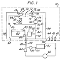
- the apparatus illustrated comprises a spray unit 10 having a through-passage 12 for at least one conductor covered with polymeric insulation.
- the through-passage extends normally to the plane of Figure 1 and the spray unit is provided with spray means arranged for spraying a polyol-water mixture onto the polymeric insulation of the or each conductor during its passage through the spray unit.
- the spray means comprise two spray nozzles 14 directed towards the through-passage for spraying the mixture over the entire outer surface of the insulation of the or each conductor as it passes through the through-passage 12. It will however be appreciated that more than two such spray nozzles may be provided.
- Each spray nozzle has an inlet 16 for the mixture of polyol-water and an inlet 18 for compressed air and is arranged to produce an atomised spray of the mixture.
- the apparatus includes a container 20 for containing a quantity of the polyol-water mixture.
- a conduit 22 connects the container 20 via a control valve 24 and monitoring unit 26 to a pump 28 of the spray unit.
- the pump 28 is pneumatically operated and connected to a compressed air supply by conduits 30 and 32.
- the conduit 30 also supplies compressed air to further conduits 34 and 36 which are connected to each spray nozzle 14, the conduit 34 being connected to the compressed air inlet 18 and the conduit 36 being connected to an inlet 38 of a pneumatically operated valve arrangement of each nozzle.
- In the conduit 30 upstream of the conduits 32, 34 and 36 there is provided in line a pressure limiting switch 40, a solenoid operated valve 42 and a filter 44.
- the pressure limiting switch is set to limit the air pressure to a predetermined value, for example 80 psi.
- a spray control valve 46 is provided in the conduit 34 to enable the amount of air being supplied to each nozzle to be controlled.
- this spray control valve may have four operating conditions and is switchable between those conditions to provide four different spray patterns from the nozzle 12.
- a conduit 48 is connected to the outlet 50 of the pump 28 and via two branches 52 and 54 to the respective mixture inlets 16 of the two nozzles.
- Each branch 52 and 54 includes a filter 56 and a flow sensor 58.
- the spray unit 10 also includes a collection tank 60 disposed in the unit to collect residual sprayed mixture, i.e. mixture which has been sprayed by the nozzles but does not leave the spray unit on the polymeric insulation. This residual mixture is redirected via conduit 62, filter 64 and pump 66 to the mixture container 20.
- the collection tank 60 is provided with respective low and high level limit switches 68 and 70. These limit switches control operation of the pump 66 and can also be utilised to provide alarm signals.
- a signal from the low level limit switch 68 can be arranged to provide an alarm indicating that the quantity of mixture in the apparatus has fallen below a predetermined level and that further mixture has to be added to the collection tank.
- An alarm signal from the high level limit can be used to indicate that the amount of further mixture added has brought the quantity in the system to a predetermined maximum amount.
- the solenoid valve 42 is actuated to supply compressed air to the pump 28 to drive the same, to the pneumatically controlled valve of each nozzle 12 to actuate those nozzles and to the air inlets 18 of the nozzles.
- the pump 28 pumps mixture from the container 20 to the two nozzles 14 where the mixture is atomised by the compressed air and sprayed onto the insulation of a conductor core passing through the through-passage 12 of the spray unit. Residual sprayed mixture is collected in the collection tank and returned by pump 66 to the container 20.
- the monitoring unit 26 monitors the supply of mixture from the container 20 to provide an indication of the volume ratio of the polyol to water of the mixture.
- the monitoring unit may for example monitor the viscosity of the supply of mixture or alternatively the density of this supply to provide an indication of its volume ratio.
- the volume ratio of polyol to water in the system illustrated in Figure 1 can be adjusted by adding either polyol or water to the collection tank 60.
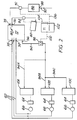
- FIG. 2 there is illustrated an alternative apparatus which comprises more than one spray unit, wherein all of the spray units are provided with a common supply of polyol-water mixture.
- three such spray units are provided and are indicated by the reference numerals 10A, 10B and 10C.
- Each of these units is identical in construction to the spray unit 10 of the apparatus illustrated in Figure 1.
- each unit is provided with a conduit 62 from the collection tank thereof for returning residual mixture via a filter 64 and pump 66 to a mixture container.
- the container is common to the three spray units.
- This common container is referenced 72 and in addition to being provided with three inlets 74 for residual mixture from the spray units has separate inlets 76 and 78 for polyol and water.
- the inlets may be connected to a mixing jet or other mixing means diagrammatically illustrated at 80 to ensure that the polyol and water is thoroughly mixed as it enters the container.
- the polyol inlet 76 is connected to a supply of polyol, schematically illustrated as a drum 82 containing polyol, via a dosing pump 84.
- the water inlet 78 is connected to a demineralised water unit 86 which is arranged to be supplied with mains water through an inlet 88 and control valve 90, a dosing pump 92 being provided to control the supply of demineralised water from the unit 86 to the water inlet 78 of the container 72.
- the mixture of polyol and water in the container 72 is supplied via a common conduit 94 and thereafter branch conduits 94A, 94B and 94C to the individual spray units.
- the common conduit 94 is provided with a stop valve 96 and also incorporates a monitoring unit 98 corresponding to the monitoring unit 26 provided in the apparatus illustrated in Figure 1.
- the monitoring unit 98 is connected via a signal transmitting line 100 to a control unit 102 to provide a signal to that unit indicative of the volume ratio of polyol to water thereof.
- the signal is used to control actuation of the dosing pumps 84 and 92, which are connected to the control unit 102 by respective power lines 104 and 106, to maintain the volume ratio within predetermined limits.
- the apparatus illustrated in Figure 2 which provides automatic maintenance of the polyol to water volume ratio may incorporate only one spray unit although it is particularly advantageous to incorporate more than one spray unit in the apparatus.
- each respective spray unit may be used to spray a single insulated conductor core passing through it or alternatively more than one insulated conductor core.
- the sprayed conductor cores from the spray units may be fed into a common extruder for extruding polymeric insulation over those conductor cores, or into respective extruders such that the sprayed core or cores from each unit is fed into a different extruder.
- the amount of polyol in the polyol-water mixture may be reduced if a surfactant is added to the mixture.
- the mixture may comprise from a half to three parts polyol to one part water by volume.
- Tests have established that a mixture comprising about one part polyol to one part water by volume produces good results when a surfactant is added to the mixture.
- the surfactant should have low electrical conductivity and a suitable surfactant is a block copolymer of ethylene oxide and propylene oxide, such as that marketed under the trade name, SYNPERONIC/PEL62 by ICI.
- the volume of the surfactant added to the mixture may comprise about 1-2% of the volume of the polyol-water mixture.
- polyols which may be used in the method are polyethylene glycol, polypropylene glycol and glycerol.
Landscapes
- Engineering & Computer Science (AREA)
- Manufacturing & Machinery (AREA)
- Compositions Of Macromolecular Compounds (AREA)
- Nozzles (AREA)
- Manufacturing Of Electric Cables (AREA)
- Extrusion Moulding Of Plastics Or The Like (AREA)
Applications Claiming Priority (4)
| Application Number | Priority Date | Filing Date | Title |
|---|---|---|---|
| GB8806939 | 1988-03-23 | ||
| GB8806939A GB2215903A (en) | 1988-03-23 | 1988-03-23 | Electrical cable manufacture |
| GB8902074 | 1989-01-31 | ||
| GB8902074A GB2217099B (en) | 1988-03-23 | 1989-01-31 | Electrical cable manufacture |
Publications (2)
| Publication Number | Publication Date |
|---|---|
| EP0334535A2 true EP0334535A2 (de) | 1989-09-27 |
| EP0334535A3 EP0334535A3 (de) | 1990-12-05 |
Family
ID=26293679
Family Applications (1)
| Application Number | Title | Priority Date | Filing Date |
|---|---|---|---|
| EP19890302521 Withdrawn EP0334535A3 (de) | 1988-03-23 | 1989-03-15 | Herstellung eines elektrischen Kabels |
Country Status (5)
| Country | Link |
|---|---|
| US (2) | US5066516A (de) |
| EP (1) | EP0334535A3 (de) |
| AU (1) | AU603506B2 (de) |
| BR (1) | BR8901538A (de) |
| NZ (1) | NZ228407A (de) |
Cited By (4)
| Publication number | Priority date | Publication date | Assignee | Title |
|---|---|---|---|---|
| EP0628972A3 (de) * | 1993-06-11 | 1995-02-22 | Bicc Plc | Elektrische Kabel. |
| EP0790081A3 (de) * | 1996-02-15 | 1998-07-15 | Singulus Technologies AG | Vorrichtung zur Oberflächenbeschichtung bzw. zum Lackieren von Substraten |
| EP0790083A3 (de) * | 1996-02-15 | 1998-07-15 | Singulus Technologies AG | Vorrichtung zur Oberflächen-beschichtung bzw. zum Lackieren von Substraten |
| FR2835449A1 (fr) * | 2002-02-04 | 2003-08-08 | Jean Philippe Laberenne | Dispositif pour l'injection de fluides supplementaires dans une rampe de pulverisateur |
Families Citing this family (7)
| Publication number | Priority date | Publication date | Assignee | Title |
|---|---|---|---|---|
| EP0334535A3 (de) * | 1988-03-23 | 1990-12-05 | PIRELLI GENERAL plc | Herstellung eines elektrischen Kabels |
| DE4201376C1 (de) * | 1992-01-20 | 1993-01-28 | Herberts Gmbh, 5600 Wuppertal, De | |
| US5360944A (en) * | 1992-12-08 | 1994-11-01 | Minnesota Mining And Manufacturing Company | High impedance, strippable electrical cable |
| US5319269A (en) * | 1993-04-13 | 1994-06-07 | Camco International Inc. | Stator windings for electric motor |
| DE69623938T2 (de) * | 1996-06-21 | 2003-05-22 | Pirelli Cavi E Sistemi S.P.A., Mailand/Milano | Gegen Wasserbäumchen widerstandsfähige Isolierungszusammensetzung |
| CH696011A5 (de) * | 2002-05-15 | 2006-11-15 | Studer Ag Draht & Kabelwerk | Strangförmiges Produkt mit Anschluss- und/oder Befestigungsmitteln. |
| US20040222012A1 (en) * | 2003-05-06 | 2004-11-11 | Electron Beam Technologies, Inc. | Small-gauge signal cable and its method of use |
Family Cites Families (21)
| Publication number | Priority date | Publication date | Assignee | Title |
|---|---|---|---|---|
| US4000362A (en) * | 1972-03-06 | 1976-12-28 | Sumitomo Electric Industries, Ltd. | Insulated wire with a silicone releasing layer |
| US3787255A (en) * | 1972-05-30 | 1974-01-22 | Essex International Inc | Insulated cable with sheath of controlled peel strength and method |
| CA955810A (en) * | 1972-06-26 | 1974-10-08 | Joseph J. Luczak | Release agent for cable compositions |
| US3953310A (en) * | 1972-09-05 | 1976-04-27 | Dainichi-Nippon Cables, Ltd. | Electrocoating process for producing insulated wire |
| US3800065A (en) * | 1973-03-26 | 1974-03-26 | Anaconda Co | Grounded power cable |
| DE2337462B2 (de) * | 1973-07-24 | 1975-11-06 | Union Carbide Canada Ltd., Toronto, Ontario (Kanada) | Elektrisch isolierter Leiter |
| DE2706768B2 (de) * | 1977-02-17 | 1980-04-24 | Basf Ag, 6700 Ludwigshafen | Verfahren zur Elektroisolierung von metallischen Leitern |
| US4370517A (en) * | 1977-12-29 | 1983-01-25 | Hitachi Cable Limited | Polyolefin compositions for electrical insulation |
| US4877467A (en) * | 1978-05-26 | 1989-10-31 | Northern Telecom Limited | Electrically insulated wire |
| US4391848A (en) * | 1978-08-07 | 1983-07-05 | Phelps Dodge Industries, Inc. | Method for manufacturing magnet wire |
| EP0015369B1 (de) * | 1979-03-05 | 1982-11-17 | kabelmetal electro GmbH | Feuchtigkeitsgeschütztes elektrisches kunststoffisoliertes Energiekabel, Verfahren zu seiner Herstellung und Vorrichtung zur Durchführung dieses Verfahrens |
| DE3044059A1 (de) * | 1979-12-18 | 1981-10-01 | Dr. Beck & Co Ag, 2000 Hamburg | Verfahren zur herstellung von wickeldraehten mit zwei isolierschichten aus unterschiedlichen materialien durch extrusion von thermoplasten |
| US4869959A (en) * | 1979-12-20 | 1989-09-26 | Northern Telecom Limited | Electrically insulated wire |
| JPS57126004A (en) * | 1981-01-30 | 1982-08-05 | Nippon Unicar Co Ltd | Semiconductive polyolefin composition and cable using same |
| EP0103307B1 (de) * | 1982-09-14 | 1990-07-25 | Nec Corporation | Wicklungsdraht |
| US4652323A (en) * | 1984-01-09 | 1987-03-24 | Olin Corporation | Plasma deposition applications for communication cables |
| DE3429745A1 (de) * | 1984-08-13 | 1986-02-20 | Lapp GmbH, 7000 Stuttgart | Verfahren zur leistungssteigerung von kabelummantelungsanlagen |
| GB8432608D0 (en) * | 1984-12-22 | 1985-02-06 | Bp Chem Int Ltd | Strippable laminate |
| US4877645A (en) * | 1988-02-26 | 1989-10-31 | American Telephone & Telegraph At&T Technologies, Inc. | Methods of and apparatus for applying a coating material to elongated material |
| EP0334535A3 (de) * | 1988-03-23 | 1990-12-05 | PIRELLI GENERAL plc | Herstellung eines elektrischen Kabels |
| GB2215903A (en) * | 1988-03-23 | 1989-09-27 | Pirelli General Plc | Electrical cable manufacture |
-
1989
- 1989-03-15 EP EP19890302521 patent/EP0334535A3/de not_active Withdrawn
- 1989-03-16 US US07/324,387 patent/US5066516A/en not_active Expired - Fee Related
- 1989-03-20 NZ NZ228407A patent/NZ228407A/en unknown
- 1989-03-21 AU AU31556/89A patent/AU603506B2/en not_active Ceased
- 1989-03-27 BR BR898901538A patent/BR8901538A/pt unknown
-
1991
- 1991-08-06 US US07/740,989 patent/US5151561A/en not_active Expired - Fee Related
Cited By (4)
| Publication number | Priority date | Publication date | Assignee | Title |
|---|---|---|---|---|
| EP0628972A3 (de) * | 1993-06-11 | 1995-02-22 | Bicc Plc | Elektrische Kabel. |
| EP0790081A3 (de) * | 1996-02-15 | 1998-07-15 | Singulus Technologies AG | Vorrichtung zur Oberflächenbeschichtung bzw. zum Lackieren von Substraten |
| EP0790083A3 (de) * | 1996-02-15 | 1998-07-15 | Singulus Technologies AG | Vorrichtung zur Oberflächen-beschichtung bzw. zum Lackieren von Substraten |
| FR2835449A1 (fr) * | 2002-02-04 | 2003-08-08 | Jean Philippe Laberenne | Dispositif pour l'injection de fluides supplementaires dans une rampe de pulverisateur |
Also Published As
| Publication number | Publication date |
|---|---|
| US5151561A (en) | 1992-09-29 |
| AU3155689A (en) | 1989-09-28 |
| AU603506B2 (en) | 1990-11-15 |
| EP0334535A3 (de) | 1990-12-05 |
| BR8901538A (pt) | 1989-11-14 |
| US5066516A (en) | 1991-11-19 |
| NZ228407A (en) | 1991-03-26 |
Similar Documents
| Publication | Publication Date | Title |
|---|---|---|
| US5066516A (en) | Electrical cable manufacture | |
| US4185650A (en) | Method and apparatus for trouble-shooting and irrigation system | |
| US5040409A (en) | Sprinkler alarm | |
| GB2217099A (en) | Electrical cable manufacture | |
| CN111305897A (zh) | 一种矿井自动化排水控制系统 | |
| CN207426698U (zh) | 一种车载总线式电源分配装置 | |
| CN219547168U (zh) | 一种涤纶纤维的纺丝设备 | |
| EP1097751A2 (de) | Überwachungssystem für eine Vorrichtung zur Spannungssperrung | |
| CA2115167C (en) | Apparatus and method for insuring and controlling turbulent flow for cleaning ducts | |
| KR100495358B1 (ko) | 질소가스를 이용한 증류수 미분무 소화 장치 | |
| EP0010743B1 (de) | Dosiervorrichtung | |
| CN202099300U (zh) | 高炉喷雾冷却装置 | |
| CN110053985B (zh) | 一种高粘度物料全自动化送料分料系统 | |
| CA2224370C (en) | Method of detecting clogging and granulation method | |
| CN1329224C (zh) | 含有远程通信控制的料槽自动卸料车 | |
| CN113156884A (zh) | 一种基于plc的模块化焦炉除尘电控系统 | |
| CN115032960A (zh) | 基于工业以太网与控制总线的现场设备控制系统及方法 | |
| CN217880094U (zh) | 一种环保节能型纸制品加湿装置 | |
| CN214586527U (zh) | 一种基于plc的模块化焦炉除尘电控系统 | |
| CN223683738U (zh) | 一种基于电子表互锁的压力罐喷胶系统 | |
| CN222178628U (zh) | 一种电线挤出机下料异常识别装置 | |
| CN211593711U (zh) | 辅助下料装置及具有其的糊树脂包装机 | |
| CN217920488U (zh) | 一种应用于货运火车卸料的云雾降尘系统 | |
| CN110065487A (zh) | 一种轨道交通制动系统用压力监控装置 | |
| JPS5761004A (en) | Supply tube for polymer latex |
Legal Events
| Date | Code | Title | Description |
|---|---|---|---|
| PUAI | Public reference made under article 153(3) epc to a published international application that has entered the european phase |
Free format text: ORIGINAL CODE: 0009012 |
|
| AK | Designated contracting states |
Kind code of ref document: A2 Designated state(s): ES FR IT |
|
| PUAL | Search report despatched |
Free format text: ORIGINAL CODE: 0009013 |
|
| AK | Designated contracting states |
Kind code of ref document: A3 Designated state(s): ES FR IT |
|
| 17P | Request for examination filed |
Effective date: 19901218 |
|
| 17Q | First examination report despatched |
Effective date: 19921105 |
|
| STAA | Information on the status of an ep patent application or granted ep patent |
Free format text: STATUS: THE APPLICATION IS DEEMED TO BE WITHDRAWN |
|
| 18D | Application deemed to be withdrawn |
Effective date: 19940125 |