EP0334464B1 - Accouplement pour tendon d'ancrage - Google Patents
Accouplement pour tendon d'ancrage Download PDFInfo
- Publication number
- EP0334464B1 EP0334464B1 EP89300025A EP89300025A EP0334464B1 EP 0334464 B1 EP0334464 B1 EP 0334464B1 EP 89300025 A EP89300025 A EP 89300025A EP 89300025 A EP89300025 A EP 89300025A EP 0334464 B1 EP0334464 B1 EP 0334464B1
- Authority
- EP
- European Patent Office
- Prior art keywords
- tension leg
- shoulder
- receptacle
- latching element
- recess
- Prior art date
- Legal status (The legal status is an assumption and is not a legal conclusion. Google has not performed a legal analysis and makes no representation as to the accuracy of the status listed.)
- Expired - Lifetime
Links
Images


Classifications
-
- B—PERFORMING OPERATIONS; TRANSPORTING
- B63—SHIPS OR OTHER WATERBORNE VESSELS; RELATED EQUIPMENT
- B63B—SHIPS OR OTHER WATERBORNE VESSELS; EQUIPMENT FOR SHIPPING
- B63B21/00—Tying-up; Shifting, towing, or pushing equipment; Anchoring
- B63B21/50—Anchoring arrangements or methods for special vessels, e.g. for floating drilling platforms or dredgers
- B63B21/502—Anchoring arrangements or methods for special vessels, e.g. for floating drilling platforms or dredgers by means of tension legs
-
- Y—GENERAL TAGGING OF NEW TECHNOLOGICAL DEVELOPMENTS; GENERAL TAGGING OF CROSS-SECTIONAL TECHNOLOGIES SPANNING OVER SEVERAL SECTIONS OF THE IPC; TECHNICAL SUBJECTS COVERED BY FORMER USPC CROSS-REFERENCE ART COLLECTIONS [XRACs] AND DIGESTS
- Y10—TECHNICAL SUBJECTS COVERED BY FORMER USPC
- Y10T—TECHNICAL SUBJECTS COVERED BY FORMER US CLASSIFICATION
- Y10T403/00—Joints and connections
- Y10T403/16—Joints and connections with adjunctive protector, broken parts retainer, repair, assembly or disassembly feature
-
- Y—GENERAL TAGGING OF NEW TECHNOLOGICAL DEVELOPMENTS; GENERAL TAGGING OF CROSS-SECTIONAL TECHNOLOGIES SPANNING OVER SEVERAL SECTIONS OF THE IPC; TECHNICAL SUBJECTS COVERED BY FORMER USPC CROSS-REFERENCE ART COLLECTIONS [XRACs] AND DIGESTS
- Y10—TECHNICAL SUBJECTS COVERED BY FORMER USPC
- Y10T—TECHNICAL SUBJECTS COVERED BY FORMER US CLASSIFICATION
- Y10T403/00—Joints and connections
- Y10T403/59—Manually releaseable latch type
Definitions
- the present invention relates to an improved joint for a tension leg and particularly to a releasable latch for such joint which can be set and released by simple axial movement of the inner leg member.
- U. S. Patent No. 3,452,815 discloses a latching mechanism for connecting lines run from a floating vessel to a subsea well which includes latching dogs to coact with a circumferential groove in the post or mandrel and carried by and other member and including an actuator means to block the dogs in latched position and preset means including a the use of a weight dropped from the surface to engage and move the actuator to a latch releasing position.
- U. S. Patent No. 4,651,818 discloses a tubing plug which is latched by dogs being cammed into an internal recess within the tubular member in which the plug is to seat. The cam is a sleeve sliding on the rod mandrel for locking and releasing the dogs from their latched position.
- U. S. Patent No. 4,611,953 discloses a tension leg platform tendon bottom connector.
- This structure provides a connection from a tubular tension leg tendon into the receptacle in the anchor template located on the sea floor.
- This connection includes dogs which are used to engage within an internal recess in the receptacle and keys which when lowered into the recess cause relative movement of the dogs to move then into an inactive position allowing removal of the tendon from the receptacle.
- U. S. Patent No. 3,448,799 discloses a well completion unit which utilizes cam actuated locking dogs to provide the clamping connection between the Christmas tree and flowline in a subsea well.
- U. S. Patent No. 3,071,188 discloses the use of a ring having depending flexible latching fingers which engage within external grooves in a tubular member and when engaged a sleeve is moved into surrounding relationship to the exterior of the fingers to secure them in their latching position.
- US-A-4451056 describes a tension leg joint in which a tension leg can be latched in a receptacle by a split ring type latching element which is normally biased outwardly to engage a shoulder on the receptacle.
- a release element is provided to release the latching element and permit retrieval of the tension leg.
- An object of the present invention is to provide an improved tension leg joint which is easy to connect into latching position and easy to release and retrieve from latching position.
- Another object is to provide an improved tension leg joint having a simple structure which does not rely upon springs for the release of the latching member from its latched position.
- a tension leg joint comprising a receptacle having an enlarged end, an upper surface tapering inwardly and away from the enlarged end, a first bore at the inner portion of said upper surface and extending downwardly therefrom, a recess below said first bore and having an enlarged diameter with respect to said first bore, an upper downwardly facing shoulder at the upper end of said recess, a lower upwardly facing shoulder at the lower end of said recess and a bore below said upwardly facing shoulder extending through the remainder of said receptacle, a tension leg having an end which is landed within said upper bore in said enlarged end of the receptacle, said tension leg end having a lower upwardly facing external shoulder between a larger external diameter surface and an intermediate external surface whose diameter is smaller than said larger surface, and an upper upwardly facing external shoulder between said intermediate external surface and a smaller external diameter surface, a latching element normally biased outwardly for seating on said lower upwardly facing external shoulder and extending radially outward of said
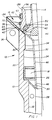
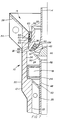
- improved tension leg joint 10 includes receptacle 12 which is supported in a well known and usual manner from the anchor template (not shown) positioned in anchoring relationship to the sea floor (not shown), and tendon or tension leg 14 which is shown to be in the initial phase of entering the upper end of receptacle 12, latching means 16 and release means 18.
- Receptacle 12 includes tubular body 20 which has bore 22 extending upward in its lower end up to the lower end of recess 24 which is defined by lower shoulder 26 which faces upwardly. Fins 28 are positioned within bore 22 as shown and support lower guide plate 30 which is frusto-conical in shape and adapted to engage and guide the lower end of tendon 14 as hereinafter described.
- the upper end of recess 24 ends in downwardly facing shoulder 32.
- the upper interior of body 20 continues above shoulder 32 with straight bore 34.
- Fins 36 are secured to the exterior of body 20 in supporting relationship to upper guide plate 38 which is generally frusto-conical in shape as is the upper surface 40 of body 20 to assist in the entry of tendon 14 into receptacle 12.
- Tendon 14 is shown to be a tubular member but may be a solid rod-like member depending upon the design requirements for the particular installation.
- the lower end of tendon 14 is engaged with spherical surface 42 supported on plate 44 from stinger 46.
- Stinger 46 includes tubular extension 48 secured at its upper end to frusto-conical support 50 to which plate 44 is secured.
- Resilient mounting means 52 is shown positioned between the exterior outer surface 54 on the lower end of tendon 14 and the lower interior of latch support ring 56 as shown.
- Such resilient mounting means may be any suitable means providing the desired degree of freedom of movement between the components.
- Latch support ring 56 has its lower end supported by the upper end of support 50 and includes an exterior configuration including upper cylindrical surface 58 on which sealing ring 60 is mounted in approximately the center portion thereof, downwardly and outwardly tapered surface 62, short cylindrical surface 64 which ends in latching shoulder 66 and lower cylindrical surface 68 below shoulder 66 which has a diameter which is smaller than the diameter of bore 34 so that ring 56 passes readily therethrough when it is properly aligned with the axis of receptacle 12.
- Latching element 70 is normally mounted in position around surface 64 and in engagement with shoulder 66.
- latching element shown in FIGURES 1 to 8, it is a split ring which is biased to have a free position substantially as shown in FIGURE 1 but have sufficient freedom of contraction so that it will move into tight engagement around the lower portion of cylindrical surface 58 below sealing ring 60 as hereinafter described and shown.
- tension leg 14 is lowered into the upper end of receptacle 12 as shown in FIGURE 1.
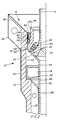
- tension leg 14 has stinger extension 48 positioned partially within lower guide plate 30 and has its axis at an angle to the axis of receptacle 12.
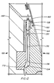
- the coaction of stinger extension 48 and plate 50 with lower guide plate 30 and upper surface 40 of body 20 during continued lowering of tension leg 14 brings the two axes into registry with each other and further allows the entry of latch support ring 58 within bore 34 of body 20. Its entry therein causes seal ring to come into engagement with the wall of bore 34 and also cams latch element 70 upward from surface 64 and inward into engagement with surfaces 62 and 58 as shown in FIGURE 2.
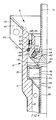
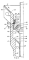
- tension leg 14 Downward movement of tension leg 14 to the position shown in FIGURE 3 frees latch element 70 so that it expands to its free diameter and drops into engagement with latching shoulder 66. At this point the lowering of tension leg 14 is stopped and tension is applied to leg 14 so that it moves upward bringing latch element 70 into engagement with shoulder 32 to securely latch tension leg 14 in this position as shown in FIGURE 4. The desired degree of tension may then be applied to tension leg 14 which will provide the mooring desired for the floating structure (not shown) to which tension leg 14 extends.
- latch element 70 has been moved above surface 64 and cammed into engagement with tapered surface 62 and upper cylindrical surface 58. Additionally the exterior of latch element 70 which includes groove 72 has been moved into engagement with the knurled surface 74 on the interior of release sleeve 76. Release sleeve 76 in its inactive position rests on shoulder 26 until engaged by latch element 70.
- tension leg 14 is raised.
- release sleeve 76 is also raised until it contacts shoulder 32 as shown in FIGURE 6. This engagement prevents further upward movement of release sleeve 76 and then latching ring 56 together with seal ring 60 and latching element 70 move upward through the interior of bore 34 as shown in FIGURE 7.
- latching element 70 has disengaged from the interior of release sleeve 76 and it has dropped within recess 24 downward into resting engagement with lower shoulder 26.
- the retrieval of tension leg 14 is completed by simply raising it and it exits from the interior of receptacle 12 as shown in FIGURE 8 and is recovered to the surface or reconnected as desired.
- release sleeve 76 with its inner knurled surface 74 or other suitable surface which provide sufficient friction force between sleeve 76 and latching element 70 for the lifting of sleeve 76 into engagement with upper shoulder 32 functions as release means 18, allowing complete release of the latched engagement between the lower end of tension leg 14 and receptacle 12.
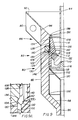
- tension leg joint 80 shown in FIGURES 9, 10, 11 and 12 is similar to joint 10 but its latching means 82 which secures the lower end of tension leg 84 within the interior of receptacle 86 is a different structure.
- Receptacle 86 includes tubular body 88 having external fins 90 in supporting relationship to upper guide plate 92 which is integral with body 88 or may be suitably secured thereto, as by welding, to provide an upward and outward continuation of upper tapered surface 94 of body 88.
- Lower bore 96 of body 88 extends upward to intersect with surface 98 which tapers upwardly and outwardly and extends to upwardly facing shoulder 100.
- Shoulder 100 forms the lower end of internal recess 102 within body 88 which extends upwardly to downwardly facing shoulder 104.
- Shoulder 104 is formed in insert 106 which is of a harder material than body 88 so that it resists coining during when it is subjected to the tension loads applied thereby by the latching means 82 as hereinafter explained. Bore 108 above shoulder 104 is straight and intersects with the inner edge of surface 94 as shown.
- Tension leg 84 includes spherical surface 110 which is engaged by the lower interior of leg 84 and provides a centering of leg 84 as it moves in pivoting relationship thereabout.
- Resilient mounting means 112 engages the interior of latching ring 114 and provides the freedom of movement required by slight angular misalignments which occur in the use of tension leg 84.
- Resilient mounting means 112 is similar to resilient mounting means 52 previously described.
- Spherical surface 110 is provide by ball segment 116 which is mounted on support plate 118 which in turn is secured to the lower exterior of latching ring 114 and stinger 120 extends downwardly therefrom as shown.
- Latching element 122 in the form of the invention illustrated in FIGURES 9 through 12, is a latch ring 124 having a plurality of flexible fingers 126 depending from ring 124. Fingers 126 include strip 128 extending from the lower end of ring 124 to the enlarged end 130 of fingers 126. Enlarged end 130 includes lower inner tapered surface 132 and upper outer tapered surface 134. Annular plate 136 is secured to the upper end of latch ring 124 by suitable fastening means 138, such as cap screws, and extends outwardly therefrom to provide a stop to the upward movement of latch ring 124. Upper exterior surface 140 on latching ring 114 tapers downwardly and slightly inwardly to upwardly facing shoulder 142.
- Cylindrical surface 146 extends downward below surface 144 and has a diameter which is sufficiently small to allow latching ring 114 to pass through bore 108.
- Latching means 82 is in the latched position with enlarged end 130 of fingers 126 engaged between shoulder 104 and tapered surface 144. In this position tension leg 84 is under tension and the upper end of latch ring 124 is spaced downwardly from the overhanging portion of annular plate 136.
- tension leg 84 which is shown to be a tubular member may be a solid tension member without departing from the features of the present invention.
- tension leg 84 is lowered into bore 108 of receptacle 86 and the engagement of the lower end of fingers 126 causes latching element 122 to move upward until its ring 124 engages the underside of annular plate 136.
- enlarged end 130 of fingers 126 is positioned to be cammed into the lower portion of tapered surface 140 above shoulder 142. This allows latching means 82 to pass through bore 108.
- the force holding fingers 126 bent inwardly is release and enlarged ends 130 move outwardly.
- tension leg 84 causes the lower inner surface 132 of enlarged end 130 to be engaged by tapered surface 144 and further upward movement brings tapered surface 134 into engagement with shoulder 104 thus completing the latching of latching means 82 which is illustrated in FIGURE 9 and 9A.
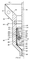
- Release sleeve 148 is positioned within recess 102 on shoulder 100.
- tension leg 84 is lowered to the position illustrated in FIGURE 10 so that enlarged ends 130 of fingers 126 are positioned within release sleeve 148 and the lower end of fingers 126 are positioned immediately above shoulder 142.
- the raising of tension leg 84 raises release sleeve 148 with latching element 122 which being release sleeve 148 into engagement with shoulder 104 as shown in FIGURE 11. Further upward movement causes enlarged ends 130 of fingers 126 to pass into bore 108 and be retrieve therefrom without any possibility of latching means 82 moving into set position.
- Joint 150 shown in FIGURE 12 is substantially the same as joint 80 except that separate release means are provided so that latching element 152 may be retracted from its latched position upward into the recess above shoulder 154 at the lower end of outer inwardly tapered surface 156. This is accomplished by the operation of bolts 158 which extend through annular plate 160 which is secured to the upper end 162 of latching ring 164. Bolts 158 are operated by divers or a remote operated vehicle and function to raise latching element 152 to its retracted position.
- tension leg 166 which allows latching ring 164 to move downward in receptacle 168 sufficiently so that the lower end of fingers 170 are cammed inwardly to their released position by their upward movement against upper shoulder 172.
- This allows full release of latching element 152 to allow retrieval of tension leg 166 from receptacle 168 even in the event that release sleeve 174 has become inactive and cannot be moved upwardly by the engagement of fingers 170 therein.
Landscapes
- Chemical & Material Sciences (AREA)
- Engineering & Computer Science (AREA)
- Combustion & Propulsion (AREA)
- Mechanical Engineering (AREA)
- Ocean & Marine Engineering (AREA)
- Quick-Acting Or Multi-Walled Pipe Joints (AREA)
- Polysaccharides And Polysaccharide Derivatives (AREA)
- Saccharide Compounds (AREA)
- Organic Low-Molecular-Weight Compounds And Preparation Thereof (AREA)
Claims (7)
- Raccord (10) de colonne sous tension, comprenant un réceptacle (12) possédant une extrémité élargie, une surface supérieure (40) inclinée vers l'intérieur en s'éloignant de l'extrémité élargie, une première lumière (34) formée à la partie interne de ladite surface supérieure et s'étendant vers le bas à partir de celle-ci, une cavité (24) placée sous la première lumière (34) et ayant un diamètre élargi par rapport à celui de la première lumière (34), un épaulement supérieur (32) tourné vers le bas, à l'extrémité supérieure de la cavité (24), un épaulement inférieur (26) tourné vers le haut, à l'extrémité inférieure de la cavité (24), et un trou (22) formé sous l'épaulement (26) tourné vers le haut et traversant le reste du réceptacle (12), une colonne sous tension (14) ayant une extrémité destinée à prendre appui dans la lumière supérieure (34) formée à l'extrémité élargie du réceptacle (12), l'extrémité de la colonne ayant un épaulement inférieur externe (66) tourné vers le haut entre une surface de plus grand diamètre externe (68) et une surface externe intermédiaire (64) dont le diamètre est plus petit que celui de la surface de plus grand diamètre (68), et un épaulement supérieur externe (62) tourné vers le haut entre la surface externe intermédiaire (64) et une surface (58) de plus petit diamètre externe, un élément de verrouillage (70) normalement rappelé vers l'extérieur afin qu'il prenne appui sur l'épaulement inférieur externe (66) tourné vers le haut et s'étendant radialement vers l'extérieur depuis ladite surface (64) de plus grand diamètre externe de l'extrémité de la colonne afin qu'il forme un verrou lorsqu'il est placé en coopération avec l'épaulement (32) tourné vers le bas de la cavité du réceptacle (24), et un dispositif de libération destiné à provoquer la libération du dispositif de verrouillage et à permettre la récupération de la colonne sous tension (14), caractérisé en ce que le dispositif de libération comprend un anneau (18) de libération placé à l'intérieur de la cavité du réceptacle (24) et ayant une configuration tubulaire qui a une surface interne dont le diamètre interne est légèrement supérieur au plus grand diamètre externe de l'extrémité de la colonne sous tension, la descente de l'extrémité de la colonne sous tension dans ladite lumière supérieure formée à l'extrémité élargie du réceptacle (12) provoquant la descente de l'élément de verrouillage (70) en contact entre l'épaulement supérieur (32) de la cavité et l'épaulement inférieur externe (66) de l'extrémité de la colonne afin que la colonne (14) soit verrouillée en prise à l'intérieur du réceptacle (12) pendant que le raccord (10) est maintenu sous tension, la descente de la colonne (14) depuis sa position verrouillée assurant le contact entre l'élément de verrouillage (70) et la surface interne rugueuse de l'anneau de libération (18) afin que l'élément de verrouillage (70) soit déplacé en position sur ledit épaulement supérieur (62) de l'extrémité de la colonne sous tension par contact de l'anneau de libération (18) et de l'élément de verrouillage (70), et des moyens agissant entre l'élément de verrouillage (70) et l'anneau de libération (18) et provoquant le maintien du contact lors du déplacement vers le haut de l'anneau de libération (18) et de l'élément de verrouillage (70) jusqu'à ce que l'élément de verrouillage (70) dépasse l'épaulement supérieur (32) de la cavité et permette ainsi l'extraction de la colonne (14) du réceptacle (12), le contact de l'anneau de libération (18) avec l'épaulement supérieur (32) de la cavité permettant à l'extrémité de la colonne de passer à travers lorsqu'elle est extraite.
- Raccord de colonne sous tension selon la revendication 1, dans lequel l'élément de verrouillage est un anneau fendu (70) ayant des surfaces supérieure et inférieure destinées à coopérer avec l'épaulement supérieur (32) de la cavité et l'épaulement inférieur (66) de la colonne sous tension.
- Raccord de colonne sous tension selon la revendication 1, dans lequel l'élément de verrouillage est un anneau (124) ayant plusieurs doigts flexibles (126) dépassant vers le bas et ayant des surfaces de verrouillage (132, 134) à leurs extrémités.
- Raccord de colonne sous tension selon la revendication 1, comprenant un dispositif (52) de montage flexible de la colonne (14), placé à l'extrémité de la colonne sous tension.
- Raccord de colonne sous tension selon la revendication 1, comprenant un mécanisme (158, 160) destiné à libérer positivement l'élément de verrouillage (152) depuis l'extérieur de l'extrémité de la colonne.
- Raccord de colonne sous tension selon la revendication 5, dans lequel le mécanisme comporte une plaque (160) fixée à l'extrémité supérieure de l'extrémité de la colonne, et un dispositif fileté (158) passant à travers la plaque et se vissant dans l'élément de verrouillage (152) afin que la rotation du dispositif fileté provoque un soulèvement de l'élément de verrouillage à un niveau tel que son épaulement inférieur soit au-dessus de l'épaulement supérieur (154) de la colonne et permette l'extraction de la colonne du réceptacle.
- Raccord de colonne sous tension selon la revendication 1, comprenant une surface moletée formée à l'intérieur de l'anneau de libération (18) afin qu'elle retienne l'élément de verrouillage (70) pendant l'extraction de l'élément de verrouillage de l'intérieur de la cavité du réceptacle.
Applications Claiming Priority (2)
| Application Number | Priority Date | Filing Date | Title |
|---|---|---|---|
| US172191 | 1980-07-25 | ||
| US07/172,191 US4869615A (en) | 1988-03-23 | 1988-03-23 | Tension leg joint |
Publications (3)
| Publication Number | Publication Date |
|---|---|
| EP0334464A2 EP0334464A2 (fr) | 1989-09-27 |
| EP0334464A3 EP0334464A3 (en) | 1990-07-11 |
| EP0334464B1 true EP0334464B1 (fr) | 1993-05-05 |
Family
ID=22626712
Family Applications (1)
| Application Number | Title | Priority Date | Filing Date |
|---|---|---|---|
| EP89300025A Expired - Lifetime EP0334464B1 (fr) | 1988-03-23 | 1989-01-04 | Accouplement pour tendon d'ancrage |
Country Status (4)
| Country | Link |
|---|---|
| US (1) | US4869615A (fr) |
| EP (1) | EP0334464B1 (fr) |
| DE (1) | DE68906299T2 (fr) |
| NO (1) | NO176430C (fr) |
Families Citing this family (18)
| Publication number | Priority date | Publication date | Assignee | Title |
|---|---|---|---|---|
| NO166626C (no) * | 1988-06-29 | 1991-08-21 | Kvaerner Brug Kjoleavdelning | Innretning for forankring av stagene til en marin strekkforankringsplattform i et fundament paa sjoebunnen. |
| US5020942A (en) * | 1990-06-29 | 1991-06-04 | Vetco Gray Inc. | Alignment device for a tension leg platform tendon top connector |
| US5244313A (en) * | 1992-06-19 | 1993-09-14 | Abb Vetco Gray Inc. | Ratcheting segments for TLP connector |
| US5672112A (en) * | 1995-11-16 | 1997-09-30 | Sikorsky Aircraft Corporation | Zero clearance locking mechanism for a disconnect coupling device |
| US5984585A (en) * | 1996-09-27 | 1999-11-16 | Abb Vetco Gray Inc. | Vertical stab tendon bottom connector and method for securing and releasing the same |
| USRE38458E1 (en) * | 1996-09-27 | 2004-03-09 | Abb Vetco Gray Inc. | Vertical stab tendon bottom connector and method for securing and releasing the same |
| NO311686B1 (no) * | 1998-08-13 | 2002-01-07 | Kvaerner Oilfield Prod As | Konnektor beregnet til bruk på strekkstagplattform |
| NO309240B1 (no) * | 1999-03-11 | 2001-01-02 | Halliburton As | Fremgangsmåte tilpasset for bruk ved plassering av et sugeanker med en tilordnet ankerkjetting eller lignende på havbunnen, samt anordning ved et slikt sugeanker |
| GB2394498B (en) * | 2002-10-23 | 2006-08-09 | Engineering Business Ltd | Mounting of offshore structures |
| GB0306547D0 (en) * | 2003-03-21 | 2003-04-23 | Engineering Business Ltd | Apparatus for creating a local reduction in wave height |
| DE602005011019D1 (de) * | 2004-08-03 | 2008-12-24 | Ihc Engineering Business Ltd | D gerät |
| GB0503083D0 (en) * | 2005-02-15 | 2005-03-23 | Engineering Business Ltd | Launch and recovery apparatus and method |
| GB2428656B (en) | 2005-08-01 | 2009-08-05 | Engineering Business Ltd | Gangway apparatus |
| GB2434823A (en) * | 2006-02-06 | 2007-08-08 | Engineering Business Ltd | Transport and installation of offshore structures |
| US7540692B2 (en) * | 2006-06-16 | 2009-06-02 | Vetco Gray Inc. | System, method, and apparatus for locking down tendon or riser moorings |
| US7621698B2 (en) * | 2007-10-03 | 2009-11-24 | Vetco Gray Inc. | Rotating lock ring bottom tendon connector |
| GB2497953A (en) * | 2011-12-22 | 2013-07-03 | Subsea Riser Products Ltd | Preloaded Mooring Connector |
| NL2014049B1 (en) | 2014-12-23 | 2016-10-12 | Ihc Holland Ie Bv | Pile upending system. |
Family Cites Families (15)
| Publication number | Priority date | Publication date | Assignee | Title |
|---|---|---|---|---|
| US3071188A (en) * | 1958-10-29 | 1963-01-01 | Otis Eng Co | Remotely controlled latch for well tools |
| US3448799A (en) * | 1961-08-09 | 1969-06-10 | Cameron Iron Works Inc | Well completion apparatus |
| GB1024537A (en) * | 1963-10-30 | 1966-03-30 | Neue Argus Gmbh | Push-in pipeline coupling with displaceable unlocking ring |
| US3452815A (en) * | 1967-07-31 | 1969-07-01 | Regan Forge & Eng Co | Latching mechanism |
| SU417673A2 (fr) * | 1972-04-03 | 1974-02-28 | ||
| US4045054A (en) * | 1972-09-28 | 1977-08-30 | Hydrotech International, Inc. | Apparatus for rigidly interconnecting misaligned pipe ends |
| GB2033463B (en) * | 1978-10-07 | 1982-06-16 | Fmc Corp | Method and apparatus for releasably connecting together two objects |
| US4459931A (en) * | 1978-10-07 | 1984-07-17 | Fmc Corporation | Method and apparatus for tension setting and compression releasing tubular connectors |
| GB2068320B (en) * | 1980-01-30 | 1983-11-30 | Vickers Ltd | Marine tether anchoring device |
| US4451056A (en) * | 1980-07-18 | 1984-05-29 | Armco Inc. | Remotely operated underwater tension connector |
| US4320993A (en) * | 1980-07-28 | 1982-03-23 | Conoco Inc. | Tension leg platform mooring tether connector |
| US4643466A (en) * | 1984-03-29 | 1987-02-17 | American Cast Iron Pipe Company | Pipe joint assembly with snap ring and associated method |
| IT1210110B (it) * | 1984-07-09 | 1989-09-06 | Tecnomare Spa | Giunto meccanico reversibile per ancoraggi in tensione. |
| US4611953A (en) * | 1985-11-01 | 1986-09-16 | Vetco Offshore Industries, Inc. | TLP tendon bottom connector |
| US4651818A (en) * | 1986-05-12 | 1987-03-24 | Exxon Production Research Co. | Metal seal tubing plug |
-
1988
- 1988-03-23 US US07/172,191 patent/US4869615A/en not_active Expired - Fee Related
-
1989
- 1989-01-04 DE DE8989300025T patent/DE68906299T2/de not_active Expired - Fee Related
- 1989-01-04 EP EP89300025A patent/EP0334464B1/fr not_active Expired - Lifetime
- 1989-03-16 NO NO891139A patent/NO176430C/no unknown
Also Published As
| Publication number | Publication date |
|---|---|
| NO176430C (no) | 1995-04-05 |
| NO891139D0 (no) | 1989-03-16 |
| US4869615A (en) | 1989-09-26 |
| EP0334464A3 (en) | 1990-07-11 |
| DE68906299T2 (de) | 1993-08-12 |
| DE68906299D1 (de) | 1993-06-09 |
| EP0334464A2 (fr) | 1989-09-27 |
| NO176430B (no) | 1994-12-27 |
| NO891139L (no) | 1989-09-25 |
Similar Documents
| Publication | Publication Date | Title |
|---|---|---|
| EP0334464B1 (fr) | Accouplement pour tendon d'ancrage | |
| US6516887B2 (en) | Method and apparatus for tensioning tubular members | |
| US4856594A (en) | Wellhead connector locking device | |
| US4459933A (en) | Marine tether anchoring device | |
| US5107931A (en) | Temporary abandonment cap and tool | |
| US4836288A (en) | Casing hanger and packoff running tool | |
| CA1258278A (fr) | Connecteur a cliquet | |
| EP2329100B1 (fr) | Raccord de colonne montante | |
| US4459931A (en) | Method and apparatus for tension setting and compression releasing tubular connectors | |
| EP0292084B1 (fr) | Connecteur pour une installation de production | |
| US4347012A (en) | Method and apparatus for tension setting and compression releasing tubular connectors | |
| US4715445A (en) | Latch and retrieving assembly | |
| US6536527B2 (en) | Connection system for catenary riser | |
| GB2033463A (en) | Method and apparatus for releasably connecting together two objects | |
| US7621698B2 (en) | Rotating lock ring bottom tendon connector | |
| US4374630A (en) | Anchor connector for tension leg | |
| US4697828A (en) | Wellhead body lockdown and method for engaging same | |
| US5069287A (en) | Retrievable guide base for subsea well | |
| US6516875B2 (en) | Tubing hanger lockdown mechanism | |
| US4569404A (en) | Mudline casing hanger | |
| US20130146298A1 (en) | Subsea running tool with emergency release | |
| US5010952A (en) | Tubular member secured within a well support member with a preload | |
| GB2079844A (en) | Remotely operable connectors | |
| US6568875B1 (en) | Connector intended for use with tension leg platform | |
| GB2218444A (en) | Casing hanger and packoff running tool |
Legal Events
| Date | Code | Title | Description |
|---|---|---|---|
| PUAI | Public reference made under article 153(3) epc to a published international application that has entered the european phase |
Free format text: ORIGINAL CODE: 0009012 |
|
| AK | Designated contracting states |
Kind code of ref document: A2 Designated state(s): DE FR GB NL |
|
| RAP1 | Party data changed (applicant data changed or rights of an application transferred) |
Owner name: CAMERON IRON WORKS USA, INC. (A DELAWARE CORP.) |
|
| PUAL | Search report despatched |
Free format text: ORIGINAL CODE: 0009013 |
|
| AK | Designated contracting states |
Kind code of ref document: A3 Designated state(s): DE FR GB NL |
|
| 17P | Request for examination filed |
Effective date: 19901217 |
|
| 17Q | First examination report despatched |
Effective date: 19911210 |
|
| RAP1 | Party data changed (applicant data changed or rights of an application transferred) |
Owner name: COOPER INDUSTRIES INC. |
|
| GRAA | (expected) grant |
Free format text: ORIGINAL CODE: 0009210 |
|
| AK | Designated contracting states |
Kind code of ref document: B1 Designated state(s): DE FR GB NL |
|
| REF | Corresponds to: |
Ref document number: 68906299 Country of ref document: DE Date of ref document: 19930609 |
|
| ET | Fr: translation filed | ||
| PLBE | No opposition filed within time limit |
Free format text: ORIGINAL CODE: 0009261 |
|
| STAA | Information on the status of an ep patent application or granted ep patent |
Free format text: STATUS: NO OPPOSITION FILED WITHIN TIME LIMIT |
|
| 26N | No opposition filed | ||
| PGFP | Annual fee paid to national office [announced via postgrant information from national office to epo] |
Ref country code: GB Payment date: 19941219 Year of fee payment: 7 |
|
| PGFP | Annual fee paid to national office [announced via postgrant information from national office to epo] |
Ref country code: FR Payment date: 19950113 Year of fee payment: 7 |
|
| PGFP | Annual fee paid to national office [announced via postgrant information from national office to epo] |
Ref country code: DE Payment date: 19950125 Year of fee payment: 7 |
|
| PGFP | Annual fee paid to national office [announced via postgrant information from national office to epo] |
Ref country code: NL Payment date: 19950131 Year of fee payment: 7 |
|
| PG25 | Lapsed in a contracting state [announced via postgrant information from national office to epo] |
Ref country code: GB Effective date: 19960104 |
|
| REG | Reference to a national code |
Ref country code: GB Ref legal event code: 732E |
|
| PG25 | Lapsed in a contracting state [announced via postgrant information from national office to epo] |
Ref country code: NL Effective date: 19960801 |
|
| GBPC | Gb: european patent ceased through non-payment of renewal fee |
Effective date: 19960104 |
|
| PG25 | Lapsed in a contracting state [announced via postgrant information from national office to epo] |
Ref country code: FR Effective date: 19960930 |
|
| NLV4 | Nl: lapsed or anulled due to non-payment of the annual fee |
Effective date: 19960801 |
|
| REG | Reference to a national code |
Ref country code: FR Ref legal event code: ST |
|
| PG25 | Lapsed in a contracting state [announced via postgrant information from national office to epo] |
Ref country code: DE Effective date: 19961203 |