EP0334412A1 - Device for controlling the dynamic stresses transmitted by the rolling surface to the body of a vehicle, in particular a rail and tram vehicle - Google Patents
Device for controlling the dynamic stresses transmitted by the rolling surface to the body of a vehicle, in particular a rail and tram vehicle Download PDFInfo
- Publication number
- EP0334412A1 EP0334412A1 EP89200477A EP89200477A EP0334412A1 EP 0334412 A1 EP0334412 A1 EP 0334412A1 EP 89200477 A EP89200477 A EP 89200477A EP 89200477 A EP89200477 A EP 89200477A EP 0334412 A1 EP0334412 A1 EP 0334412A1
- Authority
- EP
- European Patent Office
- Prior art keywords
- signal
- suspension
- value
- acceleration
- vehicle
- Prior art date
- Legal status (The legal status is an assumption and is not a legal conclusion. Google has not performed a legal analysis and makes no representation as to the accuracy of the status listed.)
- Withdrawn
Links
Images

Classifications
-
- B—PERFORMING OPERATIONS; TRANSPORTING
- B61—RAILWAYS
- B61F—RAIL VEHICLE SUSPENSIONS, e.g. UNDERFRAMES, BOGIES OR ARRANGEMENTS OF WHEEL AXLES; RAIL VEHICLES FOR USE ON TRACKS OF DIFFERENT WIDTH; PREVENTING DERAILING OF RAIL VEHICLES; WHEEL GUARDS, OBSTRUCTION REMOVERS OR THE LIKE FOR RAIL VEHICLES
- B61F5/00—Constructional details of bogies; Connections between bogies and vehicle underframes; Arrangements or devices for adjusting or allowing self-adjustment of wheel axles or bogies when rounding curves
- B61F5/02—Arrangements permitting limited transverse relative movements between vehicle underframe or bolster and bogie; Connections between underframes and bogies
- B61F5/22—Guiding of the vehicle underframes with respect to the bogies
- B61F5/24—Means for damping or minimising the canting, skewing, pitching, or plunging movements of the underframes
- B61F5/245—Means for damping or minimising the canting, skewing, pitching, or plunging movements of the underframes by active damping, i.e. with means to vary the damping characteristics in accordance with track or vehicle induced reactions, especially in high speed mode
-
- B—PERFORMING OPERATIONS; TRANSPORTING
- B61—RAILWAYS
- B61F—RAIL VEHICLE SUSPENSIONS, e.g. UNDERFRAMES, BOGIES OR ARRANGEMENTS OF WHEEL AXLES; RAIL VEHICLES FOR USE ON TRACKS OF DIFFERENT WIDTH; PREVENTING DERAILING OF RAIL VEHICLES; WHEEL GUARDS, OBSTRUCTION REMOVERS OR THE LIKE FOR RAIL VEHICLES
- B61F5/00—Constructional details of bogies; Connections between bogies and vehicle underframes; Arrangements or devices for adjusting or allowing self-adjustment of wheel axles or bogies when rounding curves
- B61F5/02—Arrangements permitting limited transverse relative movements between vehicle underframe or bolster and bogie; Connections between underframes and bogies
- B61F5/04—Bolster supports or mountings
- B61F5/12—Bolster supports or mountings incorporating dampers
- B61F5/127—Bolster supports or mountings incorporating dampers with fluid as a damping medium
Definitions
- the present invention relates to a device for controlling the dynamic stresses transmitted by the rolling surface to the body of a vehicle, in particular of a rail and tram vehicle.
- suspensions are therefore capable of yielding satisfactory performances only under certain conditions, and for certain intensitites and/or directions of the dynamic stresses which appear during the traveling of the vehicle, for which they display a more or less optimum behaviour. In different situations, on the contrary, they show to be insufficient in order to secure a good comfort to the passengers of the vehicle.
- the purpose of the present invention is to provide a device for controlling the dynamic stresses transmitted by the rolling surface to the body of a vehicle, in particular a rail and tram vehicle, which is capable of supplying differentiated performances of the elements of the suspension, method to the different dynamic conditions which occur from time to time during the traveling of the vehicle, thus securing a better comfort for the passengers of the same vehicle.
- the modulus and/or the frequency of the dynamic stresses of any kinds, applied to the traveling vehicle are hence recognized.
- the device finds out and performs the modifications in the characteristics of the elastic components and of the damping components of the suspension.
- a device can be applied both to vehicle running on rail, in which case the acceleration should be suitably detected by detecting its three components, i.e.: in the traveling direction, transversely to the running direction and perpendicularly to the rolling plane; and to road vehicles, in which case detecting the acceleration and correcting the characteristics of the suspension in one direction only, normally in the vertical direction, is enough.
- a constrained-drive vehicle 1 running of a track 2
- a truck 3 of trailer type which supports the body 4 of the vehicle.
- the primary suspension 7, of known type can be seen, and between the frame 6 and the vehicle body 4 the secondary suspension 8 can be seen, which supports the swing bolster 9 on which the vehicle body 4 rests.
- the elastic elements in the herein depicted specific case: air springs 10, and the damping elements, in the herein depicted specific case: vertical dampers 11 and transversal dampers 12, are visible. Also, longitudinal dampers, not shown, can be present.
- a device comprises at least one accelerometer 13, fastened to the vehicle body 4 in such a way as to detect the accelerations of the body in at least one direction of the traveling vehicle.
- the set of three accelerometers 13 is suitable for detecting the function of acceleration vs. time, decomposed into the three elementary functions according to the three reference axes as above indicated.
- the three elementary funtions defined by the accelerometers 13 are used as the inputs to a control system, which carries out adjustments in the elastic elements and in the damping elements of the suspension, suitably modifying the characteristics of said elements according to preset laws, as it will be seen hereinunder.
- a signal generator 14 is associated, in which the generated signal represents the function of the component of the acceleration in the relevant direction vs. time.
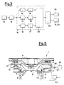
- the signal generated by each signal generator 14 is sent to a processing/comparing unit 15, in particular a microprocessor, which is capable of carrying out a processing and an evaluation of the signal, as we'll see in the following.
- the processing/comparing unit 15 essentially comprises a detector 16 which detects the amplitude of the signal indicative of the acceleration, a detector 17 which detects the fundamental frequency of the signal 14 of the acceleration and, possibly, also of the most meaningful harmonic frequencies, and a detector 18 which detects the average value of the signal 14. With each one of the detectors 16, 17 and 18, a relevant comparator 19, 20, 21 is associated, which is suitable for comparing the detected value to a relevant prefixed value.
- the output from the comparators 19, 20 and 21 is connected with a control unit 22, suitable for emitting the command signals which enable it to drive an actuator 23 according to the result of the comparisons carried out, as we'll see in the following.
- the actuator 23 acts on the elastic elements and/or on the damping elements of the secondary suspension 8, which are so made, as to be adjustable.
- the adjustment of the characteristics of the springs 10 can take place by means of the addition, or of the exclusion of one or more additional air containers 24 by means of electrovalves 25 controlled by the actuator 23.
- the adjustment of the characteristics of the damping elements 11 or 12 can take place by adjusting the passage ports between the chambers of the shock absorbers which, per se, can be of a known type. The adjustment of the passage ports will be carried out by means of the actuator 23.
- the symbols f xm , f ym , f zm indicate prefixed minimum values of frequency of acceleration signals, as respectively detected in the three x , y , z directions; the symbols A xm , A ym A zm respectively indicate prefixed minimum values of the acceleration in the three directions; and the symbols A xm , A ym , A zm indicate relevant prefixed maximum values.
- a x (t o ), A y (t o ), A z (t o ) are the values of the acceleration at the time point t o
- f x (t o ), f y (t o ), f z (t o ) are the values of frequency at time t o .
- C x , C y , C z are the coefficients of the damping elements in the three directions.
- the value of the acceleration is detected, with the values of its three different components being detected. If the value of acceleration signal is respectively lower than A xm , A ym , A zm value, prefixed as the threshold value which does not result to compromise the comfort of the passengers, no changes in the characteristics of the elastic constant, and of the damping constant of the components of the suspension are carried out, with the values of these constants being hence kept unchanged.
- the adjustment system intervenes, with it discriminating its action type, as a function of the value of the frequency of the signals of acceleration, and precisely as follows.
- the frequency value, processed in the block 15 as hereinabove disclosed is lower than the relevant prefixed minimum value (respectively f xm , f ym , f zm ), then an increase in the damping constant (C x , C y , C z ) of the damping elements 11 and 12 is commanded.
- a frequency higher than the above-said minimum value on the contrary a reduction in the damping constant is commanded.
- the action is carried out as a function of the average value of the signal of acceleration within a given time lateral ⁇ t.
- a maximization of the flexibility of the elastic components is carried out, i.e., the stiffness of the elastic suspension 8 is rendered minimum, with the value of the damping coefficient of the damping elements being simultaneously reduced to its minimum.
- a correction in the attitude of the vehicle 1 can be furthermore carried out either in continuous, or in a discrete, multi-stage way, which is essentially based on the principle consisting of decreasing the volume, and hence the height, of the suspension facing the centre of the bend along which the vehicle runs, and of increasing the volume, and hence the height, of the elastic suspension facing the outside of the bend.
- a control of the rolling angle can be carried out, in the sense of giving the vehicle body such an inclination, as to reduce the centrifugal force applied to the passengers.
- the device according to the present invention is particularly suitable for being associated with a truck of the variable-attitude type, such as the one as disclosed in Italian patent No. 1,175,889 by the same Applicant, and as shown in Figure 5.
- the processing of the accelerometric signals by the microprocessor 15 can take place both in parallel, or according to a serial route.
- a device according to the present invention could be given such a structure, as to partially act on the primary suspension, and partially on the secondary suspension, distributing and metering in an optimum way the action on both suspensions.
Abstract
The device comprises at least one accelerometer (13) so positioned, as to detect the acceleration of the body (4) of the vehicle (1) according to at least one direction, and a processing/comparing unit (15), which processes and compares the acceleration signal detected as a function of time. If the amplitude of the signal exceeds a prefixed minimum value, the frequency of the signal is determined. If this frequency exceeds a pre-established value, a reduction in the damping constant of the damping elements (11, 12) of the suspension is commanded; if, on the contrary, said frequency is lower than said prefixed value, an increase in damping constant is commanded. If the average value of the aceeleration within a given time interval is different from zero, a reduction is carried out in the flexibility of the elastic elements of the suspension (8). The contrary occurs in case of average acceleration values equating zero. The adjustment can take place by adding, or excluding, additional air containers (24) associated with air springs (8), or by adjusting the passage ports of shock absorbers.
Description
- The present invention relates to a device for controlling the dynamic stresses transmitted by the rolling surface to the body of a vehicle, in particular of a rail and tram vehicle.
- In order to reduce the dynamic stresses which, owing to the irregularities of the surface on which the vehicle wheels roll, are transmitted to the body of the vehicle during the vehicle traveling, and which, together with the forces depending on the dynamics of the vehicle, condition the vehicle passengers traveling comfort, installing elastic suspension elements and damping elements between the vehicle wheels and the vehicle body is known, and namely: the first ones, in order to absorb the irregularities of the rolling surface, and the second ones in order to dampen the consequent oscillations.
- According to the present state of the art, only components with fixed characteristics are used, with said fixed characteristics being computed as a function of average stress values, according to the type of vehicle, of the mass thereof, and so forth; and, therefore, independent from the actual values of the stress parameters, which one has at each time point, and which can change from time to time, as a function of the characteristics of the rolling surface.
- These components of the suspensions are therefore capable of yielding satisfactory performances only under certain conditions, and for certain intensitites and/or directions of the dynamic stresses which appear during the traveling of the vehicle, for which they display a more or less optimum behaviour. In different situations, on the contrary, they show to be insufficient in order to secure a good comfort to the passengers of the vehicle.
- The purpose of the present invention is to provide a device for controlling the dynamic stresses transmitted by the rolling surface to the body of a vehicle, in particular a rail and tram vehicle, which is capable of supplying differentiated performances of the elements of the suspension, method to the different dynamic conditions which occur from time to time during the traveling of the vehicle, thus securing a better comfort for the passengers of the same vehicle.
- This purpose is achieved, according to the invention, with a device for controlling the dynamic stresses transmitted by the rolling surface to the body of a vehicle, in particular a rail and tram vehicle, equipped with elastic suspension elements and with damping elements, characterized in that the elastic and/or damping elements of the suspension are adjustable elements, and that the device comprises at least one accelerometer, so positioned as to detect the accelerations of the body of the vehicle according to at least one direction of the traveling vehicle, a generator of a signal indicative, over time, of the acceleration according to said at least one direction, a signal processing/signal comparing unit, in order to compare the amplitude and/or the frequency of said signal to a prefixed value, as well as a control unit enslaved to the processing/comparing unit, in order to supply a command of change of the characteristics of the suspension whenever the value resulting from the comparison is different from said prefixed value.
- By means of the present invention, the modulus and/or the frequency of the dynamic stresses of any kinds, applied to the traveling vehicle, are hence recognized. On the basis of the processing of these parameters, detected according to at least one direction, but preferably according to three orthogonal directions, the device finds out and performs the modifications in the characteristics of the elastic components and of the damping components of the suspension.
- A device according to the present invention can be applied both to vehicle running on rail, in which case the acceleration should be suitably detected by detecting its three components, i.e.: in the traveling direction, transversely to the running direction and perpendicularly to the rolling plane; and to road vehicles, in which case detecting the acceleration and correcting the characteristics of the suspension in one direction only, normally in the vertical direction, is enough.
- More details and advantages of the invention will better result from the following disclosure, referred to a preferred form of practical embodiment of the present invention, supplied for merely indicative purposes and illustrated in the hereto attached drawings, in which:
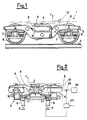
- Figure 1 shows a side view of a rail truck, to which a device according to the present invention can be applied;
- Figure 2 shows a transversal view of the truck of Figure 1, shown in partially sectional view according to path II-II of Figure 1;
- Figure 3 shows a block diagram of a device according to the invention;
- Figure 4 shows a flow diagram depicting the operating way of a device according to the invention;
- Figure 5 is a transversal, partially sectional, view of a rail truck of variable-attitude type, particularly suitable for the application of a device according to the present invention.
- Referring to the above cited figures, in the following the exemplifying case will be taken into consideration, of a constrained-drive vehicle 1 (running of a track 2), of which in Figures 1 and 2 a
truck 3 of trailer type is shown, which supports thebody 4 of the vehicle. Between thewheels 5 of thetruck 3, and theframe 6 of thetruck 3, theprimary suspension 7, of known type, can be seen, and between theframe 6 and thevehicle body 4 thesecondary suspension 8 can be seen, which supports theswing bolster 9 on which thevehicle body 4 rests. Of thesecondary suspension 8, on which the device according to the present invention performs its action, the elastic elements, in the herein depicted specific case:air springs 10, and the damping elements, in the herein depicted specific case:vertical dampers 11 andtransversal dampers 12, are visible. Also, longitudinal dampers, not shown, can be present. - A device according to the present invention comprises at least one
accelerometer 13, fastened to thevehicle body 4 in such a way as to detect the accelerations of the body in at least one direction of the traveling vehicle. Preferably threeaccelerometers 13, rigidly positioned on the structure resting on thesecondary suspension 8 are provided, so as to detect the accelerations according three orthogonal directions, and precisely in the direction of movement of the vehicle (the x axis), in the direction perpendicular to the rolling plane (the y axis), and in the direction direction to the traveling direction, and parallel to the rolling plane (the z axis). The set of threeaccelerometers 13 is suitable for detecting the function of acceleration vs. time, decomposed into the three elementary functions according to the three reference axes as above indicated. - The three elementary funtions defined by the
accelerometers 13 are used as the inputs to a control system, which carries out adjustments in the elastic elements and in the damping elements of the suspension, suitably modifying the characteristics of said elements according to preset laws, as it will be seen hereinunder. - With each accelerometer 13 a
signal generator 14 is associated, in which the generated signal represents the function of the component of the acceleration in the relevant direction vs. time. - The signal generated by each
signal generator 14 is sent to a processing/comparingunit 15, in particular a microprocessor, which is capable of carrying out a processing and an evaluation of the signal, as we'll see in the following. The processing/comparingunit 15 essentially comprises adetector 16 which detects the amplitude of the signal indicative of the acceleration, adetector 17 which detects the fundamental frequency of thesignal 14 of the acceleration and, possibly, also of the most meaningful harmonic frequencies, and adetector 18 which detects the average value of thesignal 14. With each one of thedetectors relevant comparator comparators control unit 22, suitable for emitting the command signals which enable it to drive anactuator 23 according to the result of the comparisons carried out, as we'll see in the following. Theactuator 23 acts on the elastic elements and/or on the damping elements of thesecondary suspension 8, which are so made, as to be adjustable. - In particular, on taking into consideration the case of the
air springs 10, the adjustment of the characteristics of thesprings 10 can take place by means of the addition, or of the exclusion of one or moreadditional air containers 24 by means ofelectrovalves 25 controlled by theactuator 23. The adjustment of the characteristics of thedamping elements actuator 23. - In Figure 4, a possible control typology is shown, which so designed as to make it possible the adjusting actions to be carried out on the damping elements according to the three directions x, y and z, and an adjusting action to be carried out on the elastic elements only in case transversal accelerations having determined values arise.
- In the diagram, the symbols fxm, fym, fzm indicate prefixed minimum values of frequency of acceleration signals, as respectively detected in the three x, y, z directions; the symbols Axm, Aym Azm respectively indicate prefixed minimum values of the acceleration in the three directions; and the symbols Axm, Aym, Azm indicate relevant prefixed maximum values.
- Ax(to), Ay(to), Az(to) are the values of the acceleration at the time point to, and fx(to), fy(to), fz(to) are the values of frequency at time to.
- Cx, Cy, Cz are the coefficients of the damping elements in the three directions.
- During the traveling of the
vehicle 1, at each time point the value of the acceleration is detected, with the values of its three different components being detected. If the value of acceleration signal is respectively lower than Axm, Aym, Azm value, prefixed as the threshold value which does not result to compromise the comfort of the passengers, no changes in the characteristics of the elastic constant, and of the damping constant of the components of the suspension are carried out, with the values of these constants being hence kept unchanged. - In case the amplitudes of the acceleration signals reach values higher than the above-said prefixed minimum values, and for which the comfort of the passengers is regarded as being compromised, the adjustment system intervenes, with it discriminating its action type, as a function of the value of the frequency of the signals of acceleration, and precisely as follows.
- If the frequency value, processed in the
block 15 as hereinabove disclosed, is lower than the relevant prefixed minimum value (respectively fxm, fym, fzm), then an increase in the damping constant (Cx, Cy, Cz) of thedamping elements - As regards the
elastic elements 10 of thesuspension 8, the action is carried out as a function of the average value of the signal of acceleration within a given time lateral Δt. For average values equating zero, in particular of the transversal acceleration Azmed, the only one which is taken into consideration for exemplifuing purposes in the diagram shown in Figure 4, a maximization of the flexibility of the elastic components is carried out, i.e., the stiffness of theelastic suspension 8 is rendered minimum, with the value of the damping coefficient of the damping elements being simultaneously reduced to its minimum. - For average values of the acceleration signal different from zero within the time interval Δt, in particular of the transversal component Azmed of the acceleration, a reduction is carried out in the flexibility of the elastic component of the
suspension 8, with the value of the damping coefficient of the damping elements of the suspension being simultaneously increased. - With the elastic suspensions of the above said adjustable type, a correction in the attitude of the
vehicle 1 can be furthermore carried out either in continuous, or in a discrete, multi-stage way, which is essentially based on the principle consisting of decreasing the volume, and hence the height, of the suspension facing the centre of the bend along which the vehicle runs, and of increasing the volume, and hence the height, of the elastic suspension facing the outside of the bend. In this way, a control of the rolling angle can be carried out, in the sense of giving the vehicle body such an inclination, as to reduce the centrifugal force applied to the passengers. - The device according to the present invention is particularly suitable for being associated with a truck of the variable-attitude type, such as the one as disclosed in Italian patent No. 1,175,889 by the same Applicant, and as shown in Figure 5.
- In this figure, same elements, or elements equivalent to those of the truck of Figures 1 and 2 are indicated by same reference numerals. In the variable-attitude truck, the
body 4 of thevehicle 1 is supported by theswing bolster 9 through a spherical fifth wheel 26. Therefore, thevehicle body 4 can rotate on a plane perpendicular to the direction of traveling of the vehicle, as shown in chain line in Figure 5, i.e., according to an axis parallel to the direction of movement of the vehicle, in order to reduce the effect of the centrifugal force on the passengers while the vehicle is running along bend stretches. The control of the rotation of thetruck 3 relatively to theswing bolster 9 as a function of the centrifugal force F is carried out by means ofactuator cylinders 27. The governing of the suspensions takes place in this truck in the same way as hereinabove disclosed with reference to the truck of Figure 1 and 2. - As one can see from the diagram of Figure 4, in case the acceleration results to be higher than the maximum value (respectively AxM, AyM, AzM), then the enabling of an alarm is provided.
- The processing of the accelerometric signals by the
microprocessor 15 can take place both in parallel, or according to a serial route. - With a device as hereinabove disclosed, it is therefore possible to intervene from time to time, by modifying the characteristics of the suspensions in order to match them to the needs which may occur from time to time, for the sake of a higher traveling comfort for the passengers of the vehicle.
- Beside the set of three accelerometers installed on the structure supported by the secondary suspension, also providing a second set of three accelerometers on the structure supported by the primary suspension would be of course possible, with said further set of three accelerometers being suitable for controlling the elastic characteristics, and the damping characteristics of the primary suspension.
- On course, a device according to the present invention could be given such a structure, as to partially act on the primary suspension, and partially on the secondary suspension, distributing and metering in an optimum way the action on both suspensions.
Claims (16)
1. Device for controlling the dynamic stresses transmitted by the rolling surface to the body of a vehicle, in particular a rail and tram vehicle, equipped with elastic suspension elements and with damping elements, characterized in that the elastic and/or damping elements of the suspension are adjustable elements, and that the device comprises at least one accelerometer, to positioned as to detect the accelerations of the body of the vehicle according to at least one direction of the traveling vehicle, a generator of a signal indicative, over time, of the acceleration according to said at least one direction, a signal processing/signal comparing unit, in order to compare the amplitued and/or the frequency of said signal to a prefixed value, as well as a control unit enslaved to the processing/comparing unit, in order to supply a command of change of the characteristics of the suspension whenever the value resulting from the comparison is different from said prefixed value.
2. Device according to claim 1, characterized in that it comprises three accelerometers so positioned as to be capable of detecting the accelerations according to three orthogonal directions, with one of said three directions being the direction of movement of the vehicle.
3. Device according to claim 1 or 2, characterized in that the processing unit comprises a stage suitable for determining the amplitude of the acceleration signal, a stage suitable for determining the average value of the acceleration signal, and a stage suitable for detecting the frequency of the acceleration signal.
4. Device according to one of the preceding claims, characterized in that the processing/comparing unit comprises a comparing stage suitable for comparing the value of the acceleration signal to a prefixed minimum value, a comparing stage suitable for comparing the value of frequency of the signal of acceleration to a prefixed minimum value, and a comparing step suitable for verifying whether the average acceleration value is zero or not.
5. Device according to claims 3 and 4, characterized in that the stage of processing of the frequency of the acceleration signal can be activated after that the stage of comparison of the value of the signal of acceleration has detected a value higher than said prefixed minimum value.
6. Device according to claim 1, and one of claims 4 or 5, characterized in that the control unit can be activated in order to command a maximization of the flexibility of the elastic elements of the suspension when the stage of comparison of the average value of the signal of acceleration detects a zero average value over a given time interval.
7. Device according to claim 1, and one of claims 4 or 5, characterized in that the control unit can be activated in order to command a reduction in the flexibility of the elastic elements of the suspension when the stage of comparison of the average value of the signal of acceleration detects a average value different from zero over a given time interval.
8. Device according to claim 1, and one of claims 4 or 5, characterized in that the control unit can be activated in order to command a variation in a direction of a portion of the elastic elements of the suspension, and a variation in the opposite direction of another portion of the elastic elements of the suspension.
9. Device according to claim 1, and one of claims from 4 to 8, characterized in that the control unit can be activated in order to command an increase in the damping constant of the damping elements when the frequency of the acceleration signal is lower than a prefixed value, and to command a decrease in the damping constant of the damping elements when the frequency of the acceleration signal is higher than said prefixed value.
10. Device according to one or more of the preceding claims, characterized in that the adjustable elastic elements are air springs, which can be adjusted by means of the addition, or exclusion, of additional air containers.
11. Device according to one or more of the preceding claims, characterized in that the damping elements of the suspension are shock absorbers with adjustable passage ports.
12. Device according to claims 1 or 3, characterized in that the processing/comparing unit comprises a stage of signal processing suitable for detecting the fundamental frequency of the signal, and one or more harmonics of the same signal.
13. Rail and tram truck provided with a primary suspension and a secondary suspension, characterized in that it comprises at least one device according to one of the preceding claims, suitable for controlling elastic elements and/or damping elements of at least one of said suspensions.
14. Variable-attitude rail and tram truck of the type provided with a swing bolster equipped with a spherical fifth wheel, and with attitude-actuator hydraulic cylinders, characterized in that it comprises at least one device according to one of claims from 1 to 12, suitable for controlling elastic elements and/or damping elements of at least one of the suspensions of said truck.
15. Rail and tram vehicle equipped with trucks provided with a primary suspension and a secondary suspension, characterized in that it comprises at least one device according to one of claims from 1 to 12, suitable for controlling elastic elements and/or damping elements of at least one of said suspensions.
16. Rail and tram vehicle equipped with trucks of the variable-attitude type provided with a primary suspension and a secondary suspension, characterized in that it comprises at least one device according to one of claims from 1 to 12, suitable for controlling elastic elements and/or damping elements of at least one of said suspensions.
Applications Claiming Priority (2)
| Application Number | Priority Date | Filing Date | Title |
|---|---|---|---|
| IT8819844A IT1216147B (en) | 1988-03-18 | 1988-03-18 | DEVICE FOR THE CONTROL OF DYNAMIC STRESSES TRANSMITTED FROM THE ROLLING SURFACE TO THE CASE OF A VEHICLE, IN PARTICULAR A RAILWAY VEHICLE. |
| IT1984488 | 1988-03-18 |
Publications (1)
| Publication Number | Publication Date |
|---|---|
| EP0334412A1 true EP0334412A1 (en) | 1989-09-27 |
Family
ID=11161744
Family Applications (1)
| Application Number | Title | Priority Date | Filing Date |
|---|---|---|---|
| EP89200477A Withdrawn EP0334412A1 (en) | 1988-03-18 | 1989-02-27 | Device for controlling the dynamic stresses transmitted by the rolling surface to the body of a vehicle, in particular a rail and tram vehicle |
Country Status (2)
| Country | Link |
|---|---|
| EP (1) | EP0334412A1 (en) |
| IT (1) | IT1216147B (en) |
Cited By (11)
| Publication number | Priority date | Publication date | Assignee | Title |
|---|---|---|---|---|
| EP0390546A2 (en) * | 1989-03-31 | 1990-10-03 | Hitachi, Ltd. | Railway rolling stock |
| WO1993001076A1 (en) * | 1991-07-10 | 1993-01-21 | Abb Henschel Waggon Union Gmbh | Bogie for high-speed railway vehicles |
| EP0542386A1 (en) * | 1991-11-11 | 1993-05-19 | MANNESMANN Aktiengesellschaft | Process and device for dampening the oscillations of a railway vehicle |
| TR27839A (en) * | 1992-07-09 | 1995-08-31 | Abb Henschel Waggon Union | Wheel set (bogie) for multi-speed rail vehicles. |
| WO1999054704A1 (en) * | 1998-04-17 | 1999-10-28 | Koni B.V. | System for monitoring the working of rotation or roll dampers |
| EP2361815A1 (en) * | 2010-02-18 | 2011-08-31 | Bombardier Transportation GmbH | Active coupling between undercarriage and body of a motor vehicle |
| US9758138B2 (en) | 2004-10-08 | 2017-09-12 | Horizon Global Americas Inc. | Brake control unit |
| US10040437B2 (en) | 2004-10-08 | 2018-08-07 | Horizon Global Americas Inc. | Brake control unit |
| US10363910B2 (en) | 2016-12-07 | 2019-07-30 | Horizon Global Americas Inc. | Automated gain and boost for a brake controller |
| US10946841B2 (en) | 2016-09-16 | 2021-03-16 | Horizon Global Americas Inc. | Driver and diagnostic system for a brake controller |
| EP3892516A4 (en) * | 2018-12-05 | 2022-08-24 | CRRC Changchun Railway Vehicles Co., Ltd. | Damping control method and device for shock absorber of train |
Citations (5)
| Publication number | Priority date | Publication date | Assignee | Title |
|---|---|---|---|---|
| GB2025572A (en) * | 1978-07-14 | 1980-01-23 | Hitachi Ltd | Fluid apparatus for actively controlling vibration of a vehicle |
| EP0032158A1 (en) * | 1979-07-20 | 1981-07-22 | Hitachi, Ltd. | Vibration controller for vehicle |
| EP0184960A1 (en) * | 1984-12-03 | 1986-06-18 | A.N.F. Industrie | System and process for damping undesirable movements of railway vehicles |
| GB2176162A (en) * | 1985-05-31 | 1986-12-17 | Hitachi Ltd | Apparatus for controlling vibration of vehicle |
| FR2593455A1 (en) * | 1986-01-29 | 1987-07-31 | Hitachi Ltd | DEVICE FOR CONTROLLING VIBRATIONS FOR VEHICLES. |
-
1988
- 1988-03-18 IT IT8819844A patent/IT1216147B/en active
-
1989
- 1989-02-27 EP EP89200477A patent/EP0334412A1/en not_active Withdrawn
Patent Citations (5)
| Publication number | Priority date | Publication date | Assignee | Title |
|---|---|---|---|---|
| GB2025572A (en) * | 1978-07-14 | 1980-01-23 | Hitachi Ltd | Fluid apparatus for actively controlling vibration of a vehicle |
| EP0032158A1 (en) * | 1979-07-20 | 1981-07-22 | Hitachi, Ltd. | Vibration controller for vehicle |
| EP0184960A1 (en) * | 1984-12-03 | 1986-06-18 | A.N.F. Industrie | System and process for damping undesirable movements of railway vehicles |
| GB2176162A (en) * | 1985-05-31 | 1986-12-17 | Hitachi Ltd | Apparatus for controlling vibration of vehicle |
| FR2593455A1 (en) * | 1986-01-29 | 1987-07-31 | Hitachi Ltd | DEVICE FOR CONTROLLING VIBRATIONS FOR VEHICLES. |
Cited By (19)
| Publication number | Priority date | Publication date | Assignee | Title |
|---|---|---|---|---|
| EP0390546A2 (en) * | 1989-03-31 | 1990-10-03 | Hitachi, Ltd. | Railway rolling stock |
| EP0390546A3 (en) * | 1989-03-31 | 1991-11-13 | Hitachi, Ltd. | Railway rolling stock |
| WO1993001076A1 (en) * | 1991-07-10 | 1993-01-21 | Abb Henschel Waggon Union Gmbh | Bogie for high-speed railway vehicles |
| AU652061B2 (en) * | 1991-07-10 | 1994-08-11 | Abb Henschel Waggon Union Gmbh | Bogie for high-speed railway vehicles |
| EP0542386A1 (en) * | 1991-11-11 | 1993-05-19 | MANNESMANN Aktiengesellschaft | Process and device for dampening the oscillations of a railway vehicle |
| TR27839A (en) * | 1992-07-09 | 1995-08-31 | Abb Henschel Waggon Union | Wheel set (bogie) for multi-speed rail vehicles. |
| WO1999054704A1 (en) * | 1998-04-17 | 1999-10-28 | Koni B.V. | System for monitoring the working of rotation or roll dampers |
| US6820460B1 (en) | 1998-04-17 | 2004-11-23 | Koni B.V. | System for monitoring the working of rotation or roll dampers |
| US10688977B2 (en) | 2004-10-08 | 2020-06-23 | Horizon Global Americas Inc. | Brake control unit |
| US9758138B2 (en) | 2004-10-08 | 2017-09-12 | Horizon Global Americas Inc. | Brake control unit |
| US10040437B2 (en) | 2004-10-08 | 2018-08-07 | Horizon Global Americas Inc. | Brake control unit |
| US11400903B2 (en) | 2004-10-08 | 2022-08-02 | Horizon Global Americas Inc. | Brake control unit |
| US11738729B2 (en) | 2004-10-08 | 2023-08-29 | Horizon Global Americas Inc. | Brake control unit |
| EP2361815A1 (en) * | 2010-02-18 | 2011-08-31 | Bombardier Transportation GmbH | Active coupling between undercarriage and body of a motor vehicle |
| US10946841B2 (en) | 2016-09-16 | 2021-03-16 | Horizon Global Americas Inc. | Driver and diagnostic system for a brake controller |
| US11731594B2 (en) | 2016-09-16 | 2023-08-22 | Horizon Global Americas Inc. | Driver and diagnostic system for a brake controller |
| US10363910B2 (en) | 2016-12-07 | 2019-07-30 | Horizon Global Americas Inc. | Automated gain and boost for a brake controller |
| US11440516B2 (en) | 2016-12-07 | 2022-09-13 | Horizon Global Americas Inc. | Automated gain and boost for a brake controller |
| EP3892516A4 (en) * | 2018-12-05 | 2022-08-24 | CRRC Changchun Railway Vehicles Co., Ltd. | Damping control method and device for shock absorber of train |
Also Published As
| Publication number | Publication date |
|---|---|
| IT8819844A0 (en) | 1988-03-18 |
| IT1216147B (en) | 1990-02-22 |
Similar Documents
| Publication | Publication Date | Title |
|---|---|---|
| JP3006689B2 (en) | Control device for semi-active traveling gear mechanism | |
| US6000702A (en) | Active vehicle suspension system | |
| US7063334B2 (en) | Vehicle stability system using active tilting mechanism | |
| US8855856B2 (en) | Vehicle roll control method using controllable friction force of MR dampers | |
| EP0334412A1 (en) | Device for controlling the dynamic stresses transmitted by the rolling surface to the body of a vehicle, in particular a rail and tram vehicle | |
| RU2415045C2 (en) | Suspension system of transport vehicle cabin | |
| US20060076741A1 (en) | Vehicle stability system: using active tilting mechanism as a counter measure to natural tilt | |
| JP2002192931A (en) | Suspension system having electric actuator and spring parallel to each other | |
| JPS63251318A (en) | Suspension control system adaptive to running condition of automobile | |
| KR100517208B1 (en) | Method for controlling anti-roll/anti-yaw of vehicles | |
| US8523192B2 (en) | Method and system for operating a motor vehicle | |
| US4861067A (en) | Active vehicle suspension with composite control arm | |
| US6164665A (en) | Vehicle suspension system with continuously adaptive shock absorption | |
| KR100916382B1 (en) | Position adjustment of a vehicle car body | |
| JPH0240522B2 (en) | ||
| JPS5940667B2 (en) | rocking suspension system | |
| US5706196A (en) | Method and apparatus for determining the velocity of a vehicle body | |
| JP2003320931A (en) | Railcar vibration restraining device | |
| CN210554842U (en) | Magnetic suspension vehicle control system | |
| JP3661877B2 (en) | Vibration control device for vehicle | |
| JPH10315965A (en) | Vibration controller for railroad rolling stock | |
| US6108596A (en) | Process and device for the control and/or regulation of wagon body tilt systems | |
| KR0180444B1 (en) | Car body modeling device | |
| KR0180441B1 (en) | 1/2 vehicle modeling apparatus | |
| JP2906210B2 (en) | Vehicle suspension device |
Legal Events
| Date | Code | Title | Description |
|---|---|---|---|
| PUAI | Public reference made under article 153(3) epc to a published international application that has entered the european phase |
Free format text: ORIGINAL CODE: 0009012 |
|
| AK | Designated contracting states |
Kind code of ref document: A1 Designated state(s): AT BE CH DE ES FR GB GR LI LU NL SE |
|
| 17P | Request for examination filed |
Effective date: 19900130 |
|
| 17Q | First examination report despatched |
Effective date: 19910430 |
|
| STAA | Information on the status of an ep patent application or granted ep patent |
Free format text: STATUS: THE APPLICATION IS DEEMED TO BE WITHDRAWN |
|
| 18D | Application deemed to be withdrawn |
Effective date: 19920804 |