EP0334350A1 - Gas recombination assembly for electrochemical cells - Google Patents
Gas recombination assembly for electrochemical cells Download PDFInfo
- Publication number
- EP0334350A1 EP0334350A1 EP89105236A EP89105236A EP0334350A1 EP 0334350 A1 EP0334350 A1 EP 0334350A1 EP 89105236 A EP89105236 A EP 89105236A EP 89105236 A EP89105236 A EP 89105236A EP 0334350 A1 EP0334350 A1 EP 0334350A1
- Authority
- EP
- European Patent Office
- Prior art keywords
- assembly
- cell
- accordance
- tab
- film
- Prior art date
- Legal status (The legal status is an assumption and is not a legal conclusion. Google has not performed a legal analysis and makes no representation as to the accuracy of the status listed.)
- Granted
Links
- 238000005215 recombination Methods 0.000 title claims description 9
- 230000006798 recombination Effects 0.000 title claims description 9
- 239000003054 catalyst Substances 0.000 claims abstract description 18
- 239000007789 gas Substances 0.000 claims abstract description 15
- 230000002209 hydrophobic effect Effects 0.000 claims abstract description 6
- 229920001343 polytetrafluoroethylene Polymers 0.000 claims description 14
- 239000004810 polytetrafluoroethylene Substances 0.000 claims description 14
- BASFCYQUMIYNBI-UHFFFAOYSA-N platinum Chemical compound [Pt] BASFCYQUMIYNBI-UHFFFAOYSA-N 0.000 claims description 11
- 239000003792 electrolyte Substances 0.000 claims description 7
- PXHVJJICTQNCMI-UHFFFAOYSA-N Nickel Chemical compound [Ni] PXHVJJICTQNCMI-UHFFFAOYSA-N 0.000 claims description 6
- 229910003307 Ni-Cd Inorganic materials 0.000 claims description 4
- 238000001816 cooling Methods 0.000 claims description 4
- 239000000203 mixture Substances 0.000 claims description 4
- 229910052697 platinum Inorganic materials 0.000 claims description 4
- 229910052759 nickel Inorganic materials 0.000 claims description 2
- 230000001737 promoting effect Effects 0.000 claims 2
- 230000003197 catalytic effect Effects 0.000 claims 1
- 238000010276 construction Methods 0.000 abstract description 3
- XLYOFNOQVPJJNP-UHFFFAOYSA-N water Substances O XLYOFNOQVPJJNP-UHFFFAOYSA-N 0.000 description 12
- UFHFLCQGNIYNRP-UHFFFAOYSA-N Hydrogen Chemical compound [H][H] UFHFLCQGNIYNRP-UHFFFAOYSA-N 0.000 description 7
- QVGXLLKOCUKJST-UHFFFAOYSA-N atomic oxygen Chemical compound [O] QVGXLLKOCUKJST-UHFFFAOYSA-N 0.000 description 7
- 239000001257 hydrogen Substances 0.000 description 7
- 229910052739 hydrogen Inorganic materials 0.000 description 7
- 239000001301 oxygen Substances 0.000 description 7
- 229910052760 oxygen Inorganic materials 0.000 description 7
- 238000006243 chemical reaction Methods 0.000 description 4
- 238000000034 method Methods 0.000 description 4
- 230000000712 assembly Effects 0.000 description 2
- 238000000429 assembly Methods 0.000 description 2
- 238000005868 electrolysis reaction Methods 0.000 description 2
- 230000009286 beneficial effect Effects 0.000 description 1
- 239000011230 binding agent Substances 0.000 description 1
- OJIJEKBXJYRIBZ-UHFFFAOYSA-N cadmium nickel Chemical compound [Ni].[Cd] OJIJEKBXJYRIBZ-UHFFFAOYSA-N 0.000 description 1
- 238000003490 calendering Methods 0.000 description 1
- 238000006555 catalytic reaction Methods 0.000 description 1
- 238000009833 condensation Methods 0.000 description 1
- 230000005494 condensation Effects 0.000 description 1
- 230000006378 damage Effects 0.000 description 1
- 230000007423 decrease Effects 0.000 description 1
- 230000000694 effects Effects 0.000 description 1
- 230000002401 inhibitory effect Effects 0.000 description 1
- 238000004519 manufacturing process Methods 0.000 description 1
- 238000012986 modification Methods 0.000 description 1
- 230000004048 modification Effects 0.000 description 1
- 239000004033 plastic Substances 0.000 description 1
- -1 polytetrafluoroethylene Polymers 0.000 description 1
- 230000006641 stabilisation Effects 0.000 description 1
- 238000011105 stabilization Methods 0.000 description 1
Images
Classifications
-
- H—ELECTRICITY
- H01—ELECTRIC ELEMENTS
- H01M—PROCESSES OR MEANS, e.g. BATTERIES, FOR THE DIRECT CONVERSION OF CHEMICAL ENERGY INTO ELECTRICAL ENERGY
- H01M10/00—Secondary cells; Manufacture thereof
- H01M10/42—Methods or arrangements for servicing or maintenance of secondary cells or secondary half-cells
- H01M10/52—Removing gases inside the secondary cell, e.g. by absorption
-
- Y—GENERAL TAGGING OF NEW TECHNOLOGICAL DEVELOPMENTS; GENERAL TAGGING OF CROSS-SECTIONAL TECHNOLOGIES SPANNING OVER SEVERAL SECTIONS OF THE IPC; TECHNICAL SUBJECTS COVERED BY FORMER USPC CROSS-REFERENCE ART COLLECTIONS [XRACs] AND DIGESTS
- Y02—TECHNOLOGIES OR APPLICATIONS FOR MITIGATION OR ADAPTATION AGAINST CLIMATE CHANGE
- Y02E—REDUCTION OF GREENHOUSE GAS [GHG] EMISSIONS, RELATED TO ENERGY GENERATION, TRANSMISSION OR DISTRIBUTION
- Y02E60/00—Enabling technologies; Technologies with a potential or indirect contribution to GHG emissions mitigation
- Y02E60/10—Energy storage using batteries
Definitions
- This invention relates to assemblies for use with electrochemical cells and, in particular, to assemblies for recombining gases produced in such cells.
- One technique for inhibiting water loss in electrochemical cells involves adapting the cells in such a way that the evolved oxygen and hydrogen are recombined to regenerate the lost water which is then returned to the cell electrolyte.
- This technique utilizes a catalyst, such as platinum, for catalyzing the recombination reaction.
- a catalyst such as platinum
- an assembly comprising a catalyst strip which is enveloped within a gas-porous, hydrophobic film.
- the latter film is encased between two metallic, gas-porous layers to form a sandwich construction which is configured into a spiral.
- a metallic tab is affixed to the end of the spiral and the assembly is affixed in the interior of the cell by connecting the tab to an interior section of one of the cell terminals. Straps attached to the cell electrodes also connect to this terminal section and a common connection is used for the straps and the assembly tab.
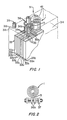
- FIG. 1 an assembly 1 in accordance with the invention is shown.
- the assembly 1 is incorporated into an electrochemical cell 31, assumed to be a Ni-Cd battery, in order to recombine the hydrogen and oxygen gases generated in the cell during overcharge. These gases are recombined by the assembly 1 to produce water which is returned to the electrolyte of the cell.
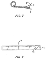
- the assembly 1 is a sandwich construction of two outer metallic, gas-porous layers 2 and 3 and an inner layer 4 which comprises a catalyst strip 4a enveloped within a hydrophobic, gas-porous film 4b.
- the sandwich is rolled, as in FIG. 3, to obtain a spiral configuration.
- the metallic layers 2 and 3 are made wider than the layer 4 and greater in length.
- the extended length of the layers provides a tab 5 (see, FIGS. 1 and 2) at the end of the spiral which facilitates mounting of the assembly 1 in the cell 31.
- the extended width portions of the layers in turn, provide cooling fins for the assembly 4, as will be described more fully below.
- the cell 31 comprises a casing 32 in which is housed an electrode structure 33 and an electrolyte 34.
- the electrode structure 33 comprises positive electrodes 33a between which are interleaved separator and negative electrode units 33b.
- Ends 35a of straps 35 connect the positive plates 33a to the lower section 36b of the positive terminal 36 of the cell.
- the terminal section 36b lies within the casing 32, while the upper section 36a of the terminal 36 extends out of the casing for connection to equipment to be supplied energy by the cell.
- a bolt 37 passes through the lower section 36b of the terminal 36 and through the straps ends 35a to effect connection of the straps and, therefore, the positive electrodes 33a, to the terminal.
- the assembly 1 is mounted in the cell 31 by also connecting the assembly to the lower section 36b of the terminal 36. This is accomplished via the above mentioned tab 5 of the assembly which is similarly bolted to the lower section 36b by the bolt 37.
- the assembly 1 constructed as above-described, recombination of the hydrogen and oxygen generated in the cell 31 occurs in a controlled manner and without significantly disturbing the efficiency of the cell.
- the generated oxygen and hydrogen pass into the assembly 1 and through the gas-porous, metallic layers 2 and 3 and the gas-porous film 4b to the catalyst strip 4a.
- the gases undergo a catalyzed recombination to produce water vapor which now passes out of the film 4b and layers 2 and 3 to be condensed at the terminal section 36b.
- the condensed water then passes back into the electrolyte 34 to replenish the water being lost in the cell by electrolysis.
- the coiled or spiral configuration of the assembly 1 is highly beneficial in allowing for a large surface area for the catalyzed recombination reaction in a small space. Further, the above-mentioned cooling fins provided by the extended widths of the two metallic layers 2 and 3 aid in controlling the heat transfer from the assembly. Additional control is achieved as a result of connection of the assembly 1 to the positive terminal 36 of the cell. This terminal now acts as a heat sink to facilitate cooling of the assembly, while at the same time places the assembly in a position where the cell gases are being formed so as to promote the recombination process. The controlled heat transfer of the assembly 1 reduces the tendency of water vapor to condense inside the film 4b and quickens the revaporization of any water that does condense.
- the catalyst strip 4a comprises a mixture of polytetrafluoroethylene (PTFE) and platinum-on-carbon.
- PTFE polytetrafluoroethylene
- the flim 4b is also comprised of PTFE.
- the roll bonded electrode method of U.S. Patent No. 3,898,099 is used to form the catalyst strip 4a as a self supporting member. More particularly, a wet mixture of PTFE and platinum-on-carbon is first calendered and dried into a .016" thick flexible sheet. A platinum loading of 5.5% of total catalyst weight is used and provides a loading of 0.5-0.6 mg. Pt/cm2.
- a 0.5" x 15" strip of catalyst is cut from the sheet.
- the strip is wrapped and sealed in an evelope of .005" thick unsintered PTFE film.
- the PTFE film is then encased between two .003" thick nickel foil layers.
- the inner layer is 3/4" wide by 17" long and the outer layer is 3/4" wide by 19 ⁇ long.
- the resultant sandwich is rolled into a tight spiral or spool of 3/4" OD x 3/4" high x 1/4" ID.
- a tab of 3/4" height x 1" length is formed at the end of the spiral by joining the nickel foil portions which extend beyond the PTFE envelope.
- the assembly is incorporated into a 100 Ah Ni-Cd battery by inserting the tab between the positive electrode straps and bolting to the positive terminal. Operation of the cell demonstrates an initial efficiency of about 45% and after stabilization an efficiency of about 85%.
- the cell 31 can be slightly pressurized to increase the residence time in the cell of the generated hydrogen and oxygen gases. This can be accomplished by use of a valve 39 in the vent hole 38 of the cell.
- a typical level of pressurization might be about 3 psi which can be achieved utilizing a spring-operated plastic valve operative at the 3 psi pressure level.
- a further modification particularly useful in hot climates or in cells having low ventillation, is to provide a canopy 41 made, for example, of nickel above the assembly 1. This will promote condensation of the water vapor outgoing from the cell.
Landscapes
- Engineering & Computer Science (AREA)
- Manufacturing & Machinery (AREA)
- Chemical & Material Sciences (AREA)
- Chemical Kinetics & Catalysis (AREA)
- Electrochemistry (AREA)
- General Chemical & Material Sciences (AREA)
- Secondary Cells (AREA)
- Hybrid Cells (AREA)
Abstract
Description
- This invention relates to assemblies for use with electrochemical cells and, in particular, to assemblies for recombining gases produced in such cells.
- It is well known that electrochemical cells and, in particular, alkaline batteries such as nickel cadmium batteries, experience a loss in the water content of the cell electrolyte during operation. This loss in water results from electrolysis which causes conversion of the water into hydrogen and oxygen during overcharge. As a result, the level of electrolyte in the cell decreases correspondingly and if this allowed to continue cell failure will occur.
- One technique for inhibiting water loss in electrochemical cells involves adapting the cells in such a way that the evolved oxygen and hydrogen are recombined to regenerate the lost water which is then returned to the cell electrolyte. This technique utilizes a catalyst, such as platinum, for catalyzing the recombination reaction. However, difficulties have been encountered in controlling the catalyzed reaction due to its highly exothermic nature. Failure to control the reaction can lead to destruction of the catalyst in smaller cells and even more severe conditions, such as cell failure, in larger cells.
- It is, therefore, a primary object of the present invention to provide an improved assembly for recombining gases produced in an electrochemical cell.
- It is a further object of the present invention to provide an catalyst assembly for recombining hydrogen and oxygen gases produced in an electrochemical cell so as to control the heat generated while preserving the efficiency and compactness of the cell.
- In accordance with the principles of the present invention, the above and other objectives are realized in an assembly comprising a catalyst strip which is enveloped within a gas-porous, hydrophobic film. The latter film, in turn, is encased between two metallic, gas-porous layers to form a sandwich construction which is configured into a spiral.
- In the embodiment of the assembly to be disclosed hereinafter, a metallic tab is affixed to the end of the spiral and the assembly is affixed in the interior of the cell by connecting the tab to an interior section of one of the cell terminals. Straps attached to the cell electrodes also connect to this terminal section and a common connection is used for the straps and the assembly tab.
- The above and other features and aspects of the present invention will become more apparent upon reading the following detailed description in conjunction with the accompanying drawings, in which:
- FIG. 1 shows an assembly in accordance with the principles of the present invention incorporated into an electrochemical cell;
- FIG. 2 shows schematically the manner of connection of the assembly in the electrochemical cell of FIG. 1;
- FIG. 3 shows the assembly of FIG. 1 in greater detail; and
- FIG. 4 shows the enveloped catalyst strip of the assembly of FIG. 1 in greater detail.
- In FIG. 1, an assembly 1 in accordance with the invention is shown.The assembly 1 is incorporated into an
electrochemical cell 31, assumed to be a Ni-Cd battery, in order to recombine the hydrogen and oxygen gases generated in the cell during overcharge. These gases are recombined by the assembly 1 to produce water which is returned to the electrolyte of the cell. - In accordance with the invention and as shown in detail in FIGS. 3 and 4, the assembly 1 is a sandwich construction of two outer metallic, gas-
porous layers 2 and 3 and aninner layer 4 which comprises acatalyst strip 4a enveloped within a hydrophobic, gas-porous film 4b. The sandwich is rolled, as in FIG. 3, to obtain a spiral configuration. - The
metallic layers 2 and 3 are made wider than thelayer 4 and greater in length. The extended length of the layers provides a tab 5 (see, FIGS. 1 and 2) at the end of the spiral which facilitates mounting of the assembly 1 in thecell 31. The extended width portions of the layers, in turn, provide cooling fins for theassembly 4, as will be described more fully below. - As shown in FIG. 1, the
cell 31 comprises acasing 32 in which is housed anelectrode structure 33 and anelectrolyte 34. Theelectrode structure 33 comprisespositive electrodes 33a between which are interleaved separator andnegative electrode units 33b. - Ends 35a of
straps 35 connect thepositive plates 33a to thelower section 36b of thepositive terminal 36 of the cell. Theterminal section 36b lies within thecasing 32, while theupper section 36a of theterminal 36 extends out of the casing for connection to equipment to be supplied energy by the cell. Abolt 37 passes through thelower section 36b of theterminal 36 and through the straps ends 35a to effect connection of the straps and, therefore, thepositive electrodes 33a, to the terminal. - In accord with the invention, the assembly 1 is mounted in the
cell 31 by also connecting the assembly to thelower section 36b of theterminal 36. This is accomplished via the above mentioned tab 5 of the assembly which is similarly bolted to thelower section 36b by thebolt 37. - With the assembly 1 constructed as above-described, recombination of the hydrogen and oxygen generated in the
cell 31 occurs in a controlled manner and without significantly disturbing the efficiency of the cell. In particular, the generated oxygen and hydrogen pass into the assembly 1 and through the gas-porous,metallic layers 2 and 3 and the gas-porous film 4b to thecatalyst strip 4a. At thestrip 4a, the gases undergo a catalyzed recombination to produce water vapor which now passes out of thefilm 4b andlayers 2 and 3 to be condensed at theterminal section 36b. The condensed water then passes back into theelectrolyte 34 to replenish the water being lost in the cell by electrolysis. - The coiled or spiral configuration of the assembly 1 is highly beneficial in allowing for a large surface area for the catalyzed recombination reaction in a small space. Further, the above-mentioned cooling fins provided by the extended widths of the two
metallic layers 2 and 3 aid in controlling the heat transfer from the assembly. Additional control is achieved as a result of connection of the assembly 1 to thepositive terminal 36 of the cell. This terminal now acts as a heat sink to facilitate cooling of the assembly, while at the same time places the assembly in a position where the cell gases are being formed so as to promote the recombination process. The controlled heat transfer of the assembly 1 reduces the tendency of water vapor to condense inside thefilm 4b and quickens the revaporization of any water that does condense. - In the present illustrative form of the invention, the
catalyst strip 4a comprises a mixture of polytetrafluoroethylene (PTFE) and platinum-on-carbon. Use of PTFE as a binder for the strip adds hydrophobicity to the strip as well as flexibility. Theflim 4b is also comprised of PTFE. - In a particular example of fabrication of an assembly 1 for use in a Ni-Cd battery, the roll bonded electrode method of U.S. Patent No. 3,898,099, assigned to the same assignee hereof, is used to form the
catalyst strip 4a as a self supporting member. More particularly, a wet mixture of PTFE and platinum-on-carbon is first calendered and dried into a .016" thick flexible sheet. A platinum loading of 5.5% of total catalyst weight is used and provides a loading of 0.5-0.6 mg. Pt/cm². - A 0.5" x 15" strip of catalyst is cut from the sheet. The strip is wrapped and sealed in an evelope of .005" thick unsintered PTFE film. The PTFE film is then encased between two .003" thick nickel foil layers. The inner layer is 3/4" wide by 17" long and the outer layer is 3/4" wide by 19˝ long. The resultant sandwich is rolled into a tight spiral or spool of 3/4" OD x 3/4" high x 1/4" ID. A tab of 3/4" height x 1" length is formed at the end of the spiral by joining the nickel foil portions which extend beyond the PTFE envelope. The assembly is incorporated into a 100 Ah Ni-Cd battery by inserting the tab between the positive electrode straps and bolting to the positive terminal. Operation of the cell demonstrates an initial efficiency of about 45% and after stabilization an efficiency of about 85%.
- In order to further enhance the gas recombination properties of the assembly 1, the
cell 31 can be slightly pressurized to increase the residence time in the cell of the generated hydrogen and oxygen gases. This can be accomplished by use of avalve 39 in thevent hole 38 of the cell. A typical level of pressurization might be about 3 psi which can be achieved utilizing a spring-operated plastic valve operative at the 3 psi pressure level. - A further modification particularly useful in hot climates or in cells having low ventillation, is to provide a
canopy 41 made, for example, of nickel above the assembly 1. This will promote condensation of the water vapor outgoing from the cell. - In all cases it is understood that the above-identified arrangements are merely illustrative of the many possible specific embodiments which represent applications of the present invention. Numerous and varied other arrangements can readily be devised in accordance with the principles of the invention without departing from the spirit and scope of the invention.
Claims (21)
a catalyst strip;
a hydrophobic, gas porous film enveloping said catalyst strip;
first and second gas-porous, metallic layers together encasing, said film to form a sandwich;
said sandwich being formed into a spiral.
a metallic tab is affixed to the outer end of said spiral.
the end of at least one of said first and second metallic layers extends beyond the end of said film and forms said tab.
the ends of both said first and second metallic layers extend beyond the end of said film and form said tab.
said metallic layers and said tab comprise nickel.
said hydrophobic, gas porous film comprises PTFE.
said PTFE is unsintered.
said catalyst comprises a mixture of platinum and PTFE.
the width of at least one of said metallic layers is greater than the width of said film, thereby forming a fin for cooling said assembly.
said hydrophoboic, gas porous film comprises PTFE.
said PTFE is unsintered.
said catalyst comprises a mixture of platinum and PTFE.
a casing;
electrode structure housed within the casing;
and an assembly mounted within the casing for promoting the recombination of gases in the cell, the assembly comprising: a catalyst strip; a hydrophobic, gas-porous film enveloping the catalyst strip; first and second gas-porous, metallic layers together encasing the film to form a sandwich;
and said sandwhich being formed into a spiral.
said assembly further includes a metallic tab affixed to the outer end of said spiral;
and said assembly is mounted in said cell via the tab.
said cell further includes a terminal mounted to said casing and having a first section extending into the interior of said casing;
and said assembly is mounted to said first section of said terminal.
said terminal is the positive terminal of said cell.
said electrode structure includes: a plurality of electrodes; and straps each attached to an electrode;
said assembly further includes a metallic tab affixed to the outer end of said spiral;
and said cell further includes means for attaching said straps and said tab to said first section of said terminal.
said means is a bolt which extends through said section, straps and tab.
said assembly further includes a metallic tab affixed to the outer end of said spiral, said tab being attached to said first section of said terminal.
said tab is formed by at least an end of one of said first and second metallic layers.
said cell is a Ni-Cd battery.
Applications Claiming Priority (2)
| Application Number | Priority Date | Filing Date | Title |
|---|---|---|---|
| US07/172,632 US4810598A (en) | 1988-03-24 | 1988-03-24 | Gas recombination assembly for electrochemical cells |
| US172632 | 1988-03-24 |
Publications (2)
| Publication Number | Publication Date |
|---|---|
| EP0334350A1 true EP0334350A1 (en) | 1989-09-27 |
| EP0334350B1 EP0334350B1 (en) | 1993-06-09 |
Family
ID=22628535
Family Applications (1)
| Application Number | Title | Priority Date | Filing Date |
|---|---|---|---|
| EP89105236A Expired - Lifetime EP0334350B1 (en) | 1988-03-24 | 1989-03-23 | Gas recombination assembly for electrochemical cells |
Country Status (4)
| Country | Link |
|---|---|
| US (1) | US4810598A (en) |
| EP (1) | EP0334350B1 (en) |
| JP (1) | JP2652236B2 (en) |
| DE (1) | DE68906936T2 (en) |
Cited By (1)
| Publication number | Priority date | Publication date | Assignee | Title |
|---|---|---|---|---|
| FR2858464A1 (en) * | 2003-07-30 | 2005-02-04 | Conseil Et De Prospective Scie | CATALYTIC RECOMBINATION DEVICE FOR ALKALINE ACCUMULATORS WITH ZINC ANODE |
Families Citing this family (10)
| Publication number | Priority date | Publication date | Assignee | Title |
|---|---|---|---|---|
| US4925746A (en) * | 1987-08-10 | 1990-05-15 | Zentralna La Boratoria Po Elektrochimicheski Iztochnici Na Tok | Device for recombing hydrogen and oxygen released in lead-acid storage batteries |
| DE4015370A1 (en) * | 1990-05-12 | 1991-11-14 | Varta Batterie | LEAD ACCUMULATOR WITH A DEVICE FOR CATALYTICALLY RECOMBINATING THE ELECTROLYSIS GASES |
| US6274263B1 (en) | 1995-10-27 | 2001-08-14 | William E. M. Jones | Semi-flooded lead acid battery cell |
| EP0948065B1 (en) * | 1998-03-30 | 2003-06-04 | Renata AG | Safety vent for accumulator or battery |
| US6372983B1 (en) | 1999-04-14 | 2002-04-16 | Ballard Generation Systems Inc. | Enclosure for electrical components installed in locations where a flammable gas or vapor is expected to be present |
| JP3497786B2 (en) * | 1999-09-29 | 2004-02-16 | Necトーキン株式会社 | Rechargeable battery |
| KR20020096732A (en) * | 2001-06-21 | 2002-12-31 | 주식회사 기노리텍 | Electric double layer parts |
| US20050092175A1 (en) * | 2003-10-29 | 2005-05-05 | Meacham G.B. K. | Noble metal gas barriers |
| US7074255B2 (en) * | 2003-10-29 | 2006-07-11 | Meacham G B Kirby | Noble metal gas barriers |
| US11652251B2 (en) * | 2020-11-02 | 2023-05-16 | ZAF Energy Systems, Incorporated | Battery state indicator based on recombination device feedback |
Citations (5)
| Publication number | Priority date | Publication date | Assignee | Title |
|---|---|---|---|---|
| DE2340945A1 (en) * | 1973-08-13 | 1975-03-20 | Varta Batterie | Accumulator stoppers contg. a catalyst - for recombination of hydrogen and oxygen to form water |
| US4078893A (en) * | 1976-06-30 | 1978-03-14 | The United States Of America As Represented By The Secretary Of The Army | Catalyst system for the detection and elimination of hydrogen gas |
| EP0037954A1 (en) * | 1980-04-10 | 1981-10-21 | VARTA Batterie Aktiengesellschaft | Stopper with gas recombination device |
| US4447508A (en) * | 1981-10-13 | 1984-05-08 | Allied Corporation | Reduced maintenance explosion damage resistant storage battery |
| EP0223058A1 (en) * | 1985-10-25 | 1987-05-27 | INTERATOM Gesellschaft mit beschränkter Haftung | Method for soldering metallic catalyst support articles |
Family Cites Families (13)
| Publication number | Priority date | Publication date | Assignee | Title |
|---|---|---|---|---|
| NL39005C (en) * | 1933-05-18 | |||
| US3102059A (en) * | 1961-02-20 | 1963-08-27 | Miranda Corp | Catalytic device for electric accumulators |
| US3287174A (en) * | 1963-11-12 | 1966-11-22 | Thomas J Hennigan | Prevention of pressure build-up in electrochemical cells |
| US3622398A (en) * | 1968-10-04 | 1971-11-23 | Matsushita Electric Industrial Co Ltd | Sealed type storage battery |
| BE755337A (en) * | 1969-08-27 | 1971-02-26 | Union Carbide Corp | HYDROGEN ABSORBING MATERIAL FOR ELECTROCHEMICAL CELLS |
| US3630778A (en) * | 1969-10-15 | 1971-12-28 | Koehler Mfg Co | Methods and means for recombining hydrogen and oxygen in a sealed battery and controlling recombination at catalyst surfaces |
| BE754850A (en) * | 1970-02-21 | 1971-01-18 | Hoppecke Zoellner Sohn Accu | DEVICE FOR THE CATALYTIC WATER RECOMBINATION OF HYDROGEN AND GASEOUS OXYGEN WHICH IS FORMED DURING THE OPERATION OF ELECTRIC ACCUMULATORS |
| US3817717A (en) * | 1970-03-06 | 1974-06-18 | Koehler Mfg Co | Apparatus for recombining hydrogen and oxygen and protectively returning water of recombination to the battery electrolyte |
| DE2326169A1 (en) * | 1973-05-23 | 1974-12-12 | Bosch Gmbh Robert | ARRANGEMENT FOR THE RECOMBINATION OF THE GASES PRODUCED IN A SECONDARY CELL |
| US3976502A (en) * | 1974-12-17 | 1976-08-24 | Matsushita Electric Industrial Co., Ltd. | Nickel-zinc alkaline storage battery |
| CA1141524A (en) * | 1980-09-29 | 1983-02-22 | Her Majesty In Right Of Canada As Represented By Atomic Energy Of Canada Limited | Gaseous hydrogen and oxygen combining and condensing device |
| US4584249A (en) * | 1984-06-27 | 1986-04-22 | The United States Of America As Represented By The Administrator Of The National Aeronautics And Space Administration | Oxygen recombination in individual pressure vessel nickel-hydrogen batteries |
| JPH116278A (en) * | 1997-06-16 | 1999-01-12 | Shin Etsu Polymer Co Ltd | Woody-toned synthetic-resin-made deck |
-
1988
- 1988-03-24 US US07/172,632 patent/US4810598A/en not_active Expired - Lifetime
-
1989
- 1989-02-27 JP JP1046355A patent/JP2652236B2/en not_active Expired - Fee Related
- 1989-03-23 EP EP89105236A patent/EP0334350B1/en not_active Expired - Lifetime
- 1989-03-23 DE DE89105236T patent/DE68906936T2/en not_active Expired - Fee Related
Patent Citations (5)
| Publication number | Priority date | Publication date | Assignee | Title |
|---|---|---|---|---|
| DE2340945A1 (en) * | 1973-08-13 | 1975-03-20 | Varta Batterie | Accumulator stoppers contg. a catalyst - for recombination of hydrogen and oxygen to form water |
| US4078893A (en) * | 1976-06-30 | 1978-03-14 | The United States Of America As Represented By The Secretary Of The Army | Catalyst system for the detection and elimination of hydrogen gas |
| EP0037954A1 (en) * | 1980-04-10 | 1981-10-21 | VARTA Batterie Aktiengesellschaft | Stopper with gas recombination device |
| US4447508A (en) * | 1981-10-13 | 1984-05-08 | Allied Corporation | Reduced maintenance explosion damage resistant storage battery |
| EP0223058A1 (en) * | 1985-10-25 | 1987-05-27 | INTERATOM Gesellschaft mit beschränkter Haftung | Method for soldering metallic catalyst support articles |
Cited By (1)
| Publication number | Priority date | Publication date | Assignee | Title |
|---|---|---|---|---|
| FR2858464A1 (en) * | 2003-07-30 | 2005-02-04 | Conseil Et De Prospective Scie | CATALYTIC RECOMBINATION DEVICE FOR ALKALINE ACCUMULATORS WITH ZINC ANODE |
Also Published As
| Publication number | Publication date |
|---|---|
| DE68906936D1 (en) | 1993-07-15 |
| US4810598A (en) | 1989-03-07 |
| JPH01267969A (en) | 1989-10-25 |
| EP0334350B1 (en) | 1993-06-09 |
| JP2652236B2 (en) | 1997-09-10 |
| DE68906936T2 (en) | 1993-11-11 |
Similar Documents
| Publication | Publication Date | Title |
|---|---|---|
| US4112199A (en) | Lanthanum nickel hydride-hydrogen/metal oxide cell | |
| US4107395A (en) | Overchargeable sealed metal oxide/lanthanum nickel hydride battery | |
| KR101296431B1 (en) | Battery and method for operating a battery | |
| US6045939A (en) | Lithium secondary battery having thermal switch | |
| US5227267A (en) | Disc electrode and busbar for an electrochemical battery | |
| EP2013927B1 (en) | Anode support member and bipolar separator for use in a fuel cell assembly and for preventing poisoning of reforming catalyst | |
| US4810598A (en) | Gas recombination assembly for electrochemical cells | |
| US4447508A (en) | Reduced maintenance explosion damage resistant storage battery | |
| KR20070040409A (en) | Fuel-cell stack comprising a tensioning device | |
| EP0697746A1 (en) | Sealed zinc secondary battery and zinc electrode therefor | |
| WO2003098648A1 (en) | Electric double layer capacitor | |
| JPH09510576A (en) | Lead battery | |
| JPH05217608A (en) | Metal oxide hydrogen battery | |
| US5460899A (en) | Sealed zinc secondary battery and zinc electrode therefor | |
| US3377201A (en) | Spiral battery cell | |
| AU650181B2 (en) | Novel sealed lead-acid cell having a novel lug and end cover assembly | |
| KR101230571B1 (en) | Device for catalytic recombination of gases for alkaline batteries with shortened zinc anode | |
| US3846175A (en) | Storage battery | |
| EP0654181B1 (en) | Improved pressure vessel for pressurized secondary cells and batteries | |
| CA1179013A (en) | Sealed, maintenance-free, lead-acid batteries for float applications | |
| US4142025A (en) | Sealed nickel cadmium battery capable of withstanding high rate overdischarge | |
| EP0024407B1 (en) | Lead acid electric storage batteries | |
| KR100968051B1 (en) | Cylindrical secondary battery with improved safety against overcharging | |
| WO1980002472A1 (en) | Electric storage batteries | |
| KR900004585Y1 (en) | Electrode assembly |
Legal Events
| Date | Code | Title | Description |
|---|---|---|---|
| PUAI | Public reference made under article 153(3) epc to a published international application that has entered the european phase |
Free format text: ORIGINAL CODE: 0009012 |
|
| AK | Designated contracting states |
Kind code of ref document: A1 Designated state(s): DE FR GB |
|
| 17P | Request for examination filed |
Effective date: 19900326 |
|
| 17Q | First examination report despatched |
Effective date: 19920123 |
|
| GRAA | (expected) grant |
Free format text: ORIGINAL CODE: 0009210 |
|
| AK | Designated contracting states |
Kind code of ref document: B1 Designated state(s): DE FR GB |
|
| REF | Corresponds to: |
Ref document number: 68906936 Country of ref document: DE Date of ref document: 19930715 |
|
| ET | Fr: translation filed | ||
| PLBE | No opposition filed within time limit |
Free format text: ORIGINAL CODE: 0009261 |
|
| STAA | Information on the status of an ep patent application or granted ep patent |
Free format text: STATUS: NO OPPOSITION FILED WITHIN TIME LIMIT |
|
| 26N | No opposition filed | ||
| REG | Reference to a national code |
Ref country code: GB Ref legal event code: 732E |
|
| REG | Reference to a national code |
Ref country code: FR Ref legal event code: TP |
|
| REG | Reference to a national code |
Ref country code: GB Ref legal event code: IF02 |
|
| PGFP | Annual fee paid to national office [announced via postgrant information from national office to epo] |
Ref country code: FR Payment date: 20030304 Year of fee payment: 15 |
|
| PGFP | Annual fee paid to national office [announced via postgrant information from national office to epo] |
Ref country code: GB Payment date: 20030319 Year of fee payment: 15 |
|
| PGFP | Annual fee paid to national office [announced via postgrant information from national office to epo] |
Ref country code: DE Payment date: 20030331 Year of fee payment: 15 |
|
| PG25 | Lapsed in a contracting state [announced via postgrant information from national office to epo] |
Ref country code: GB Free format text: LAPSE BECAUSE OF NON-PAYMENT OF DUE FEES Effective date: 20040323 |
|
| PG25 | Lapsed in a contracting state [announced via postgrant information from national office to epo] |
Ref country code: DE Free format text: LAPSE BECAUSE OF NON-PAYMENT OF DUE FEES Effective date: 20041001 |
|
| GBPC | Gb: european patent ceased through non-payment of renewal fee |
Effective date: 20040323 |
|
| PG25 | Lapsed in a contracting state [announced via postgrant information from national office to epo] |
Ref country code: FR Free format text: LAPSE BECAUSE OF NON-PAYMENT OF DUE FEES Effective date: 20041130 |
|
| REG | Reference to a national code |
Ref country code: FR Ref legal event code: ST |