EP0334036B2 - Liquid jet cutting torch - Google Patents
Liquid jet cutting torch Download PDFInfo
- Publication number
- EP0334036B2 EP0334036B2 EP89103033A EP89103033A EP0334036B2 EP 0334036 B2 EP0334036 B2 EP 0334036B2 EP 89103033 A EP89103033 A EP 89103033A EP 89103033 A EP89103033 A EP 89103033A EP 0334036 B2 EP0334036 B2 EP 0334036B2
- Authority
- EP
- European Patent Office
- Prior art keywords
- liquid
- cooling
- cutting torch
- cutting
- jet cutting
- Prior art date
- Legal status (The legal status is an assumption and is not a legal conclusion. Google has not performed a legal analysis and makes no representation as to the accuracy of the status listed.)
- Expired - Lifetime
Links
Images

Classifications
-
- F—MECHANICAL ENGINEERING; LIGHTING; HEATING; WEAPONS; BLASTING
- F23—COMBUSTION APPARATUS; COMBUSTION PROCESSES
- F23D—BURNERS
- F23D14/00—Burners for combustion of a gas, e.g. of a gas stored under pressure as a liquid
- F23D14/46—Details
- F23D14/48—Nozzles
- F23D14/52—Nozzles for torches; for blow-pipes
- F23D14/54—Nozzles for torches; for blow-pipes for cutting or welding metal
-
- B—PERFORMING OPERATIONS; TRANSPORTING
- B26—HAND CUTTING TOOLS; CUTTING; SEVERING
- B26F—PERFORATING; PUNCHING; CUTTING-OUT; STAMPING-OUT; SEVERING BY MEANS OTHER THAN CUTTING
- B26F3/00—Severing by means other than cutting; Apparatus therefor
- B26F3/004—Severing by means other than cutting; Apparatus therefor by means of a fluid jet
-
- B—PERFORMING OPERATIONS; TRANSPORTING
- B23—MACHINE TOOLS; METAL-WORKING NOT OTHERWISE PROVIDED FOR
- B23K—SOLDERING OR UNSOLDERING; WELDING; CLADDING OR PLATING BY SOLDERING OR WELDING; CUTTING BY APPLYING HEAT LOCALLY, e.g. FLAME CUTTING; WORKING BY LASER BEAM
- B23K7/00—Cutting, scarfing, or desurfacing by applying flames
Definitions
- the invention relates to a liquid jet cutting torch with a liquid jet line for high pressure liquid oxygen arranged centrally thereon, to the mouthpiece of which a cutting nozzle is attached.
- the object of the invention is to provide a liquid jet cutting torch in which the liquid jet can be cooled as close as possible to the cutting nozzle.
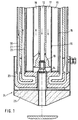
- the liquid jet cutting torches illustrated in FIGS. 1 and 2 have a centrally arranged high-pressure liquid line 12, to which a mouthpiece 13 for fastening various cutting nozzles 14 is welded.
- the high-pressure line 12 and the mouthpiece 13 are concentrically surrounded by a tube 15, which forms the line for a low-boiling, liquefied coolant, preferably liquid nitrogen.
- the line 16 for supplying the coolant is located in the annular gap 17.
- the pipe 15 is surrounded by a further concentric pipe 18, which form a space 19 for receiving vacuum insulation, preferably vacuum super insulation, which also protects the high-pressure liquid against heat radiation.
- vacuum insulation preferably vacuum super insulation
- a cooling water jacket made of stainless steel tubes 20, 21, 22 with a cooling head 23 cast from copper is pushed over the tube 18 against overheating and slag splashing.
- the copper cooling head 23 has the task of enclosing the wide mouthpiece 13 and draining the cooling water.
- the cooling head 23 is protected with a protective cap 24 made of stainless steel with a refractory mass 26.
- the cutting nozzle 24 is arranged inside the burner.
- the cutting nozzle 14 is arranged outside.
- the fireproof mass of this burner has a conical shape.
- the exposed cutting nozzle 14 is protected against splashing back slag by the escaping oxygen.
- the cooling of the nozzle 14 by the liquid oxygen cutting jet increases the protective effect.
- the conical shape of the refractory lining has the advantage that it is far less stressed than the embodiment according to FIG. 1, but the protective effect for the copper cooling head remains. This achieves a construction of the burner head that is extremely stable
Landscapes
- Engineering & Computer Science (AREA)
- Mechanical Engineering (AREA)
- Life Sciences & Earth Sciences (AREA)
- Forests & Forestry (AREA)
- General Engineering & Computer Science (AREA)
- Combustion & Propulsion (AREA)
- Chemical & Material Sciences (AREA)
- Gas Burners (AREA)
- Perforating, Stamping-Out Or Severing By Means Other Than Cutting (AREA)
- Arc Welding In General (AREA)
- Laser Beam Processing (AREA)
- Auxiliary Devices For Machine Tools (AREA)
- Disintegrating Or Milling (AREA)
- Nozzles For Spraying Of Liquid Fuel (AREA)
- Pharmaceuticals Containing Other Organic And Inorganic Compounds (AREA)
Abstract
Description
Die Erfindung betrifft einen Flüssigstrahlschneidbrenner mit einer mittig daran angeordneten Flüssigkeitsstrahlleitung für Hochdruck-Flüssigsauerstoff, an deren Mundstück eine Schneiddüse befestigt ist.The invention relates to a liquid jet cutting torch with a liquid jet line for high pressure liquid oxygen arranged centrally thereon, to the mouthpiece of which a cutting nozzle is attached.
Beim Schneiden mit einem derartigen Flüssigkeitsstrahlbrenner wie er z. B. aus der DE-A-3543 657 bekannt ist, wird der vom Tank im Siedezustand befindende Sauerstoff durch eine Hochdruckpumpe bis auf 500 bar Druck gebracht. Der Austrittsdruck aus dem Schneidbrenner wird durch ein Überströmventil festgelegt.When cutting with such a liquid jet burner as he z. B. is known from DE-A-3543 657, the oxygen in the boiling state from the tank is brought up to 500 bar pressure by a high pressure pump. The discharge pressure from the cutting torch is determined by an overflow valve.
Um die Wärme, welche durch Reibung entsteht, abzuführen, ist es erforderlich, den Sauerstoff mit einem Kühlmittel z.B. flüssigem Stickstoff zu kühlen. Hierzu ist es aus der o. g. Druckschrift lediglich bekannt, den Sauerstoff entsprechend in den Zuführungsleitungen zu kühlen.In order to dissipate the heat generated by friction, it is necessary to use a coolant, e.g. to cool liquid nitrogen. For this it is from the above. Document only known to cool the oxygen accordingly in the supply lines.
Aufgabe der Erfindung ist es, einen Flüssigstrahlschneidbrenner zu schaffen, bei dem der Flüssigstrahl möglichst nahe bis an die Schneiddüse kühlbar ist.The object of the invention is to provide a liquid jet cutting torch in which the liquid jet can be cooled as close as possible to the cutting nozzle.
Diese Aufgabe wird bei einem gattungsgemäßen Flüssigstrahlschneidbrenner durch die kennzeichnenden Merkmale des Anspruches 1 gelöst.This object is achieved in a generic liquid jet cutting torch by the characterizing features of claim 1.
Vorteilhafte Weiterbildungen der Erfindung sind in den Unteransprüchen angegeben.Advantageous developments of the invention are specified in the subclaims.
Durch die vorgesehene Doppelkühlung (tiefsiedendes, verflüssigtes Kühlmittel und Kühlwasser) mit dazwischenliegender Vakuumisolation wird ein Schneidbrenner geschaffen, bei dem der Flüssigkeitsstrahl auch noch an der Werkstückauftrittstelle ausreichend kühl ist und der gegen Überhitzung und Schlackenspritzer geschützt ist.The provided double cooling (low-boiling, liquefied coolant and cooling water) with vacuum insulation in between creates a cutting torch in which the liquid jet is also sufficiently cool at the workpiece entry point and is protected against overheating and slag splashing.
Zwei Ausführungsbeispiele der Erfindung sind in der Zeichnung dargestellt und werden im nachfolgenden näher beschrieben.Two embodiments of the invention are shown in the drawing and are described in more detail below.
Es zeigen
- Fig. 1 einen Schneidbrenner mit innenliegender Schneiddüse
- Fig. 2 einen Schneidbrenner mit außenliegender Schneiddüse.
- Fig. 1 shows a cutting torch with an internal cutting nozzle
- Fig. 2 shows a cutting torch with an external cutting nozzle.
Die in den Fig. 1 und 2 veranschaulichten Flüssigstrahlschneidbrenner weisen eine mittig angeordnete Flüssigkeitshochdruckleitung 12 auf, an der ein Mundstück 13 zur Befestigung von verschiedenen Schneiddüsen 14 angeschweißt ist. Die Hochdruckleitung 12 und das Mundstück 13 sind konzentrisch von einem Rohr 15 umgeben, welches die Leitung für ein tiefsiedendes, verflüssigtes Kühlmittel, vorzugsweise flüssigen Stickstoff, bildet. Die Leitung 16 zur Zuleitung des Kühlmittels befindet sich in dem Ringspalt 17.The liquid jet cutting torches illustrated in FIGS. 1 and 2 have a centrally arranged high-
Das Rohr 15 ist von einem weiteren konzentrischen Rohr 18 umgeben, welche zur Aufnahme einer Vakuumisolation, vorzugsweise Vakuumsuperisolation, einen Raum 19 bilden, die die Hochdruckflüssigkeit auch gegen Wärmeeinstrahlung schützt.The
Gegen Überhitzung und Schlackenspritzer ist ein Kühlwassermantel aus Edelstahlrohren 20, 21, 22, mit einem aus Kupfer gegossenem Kühlkopf 23, über das Rohr 18 geschoben. Der Kupferkühlkopf 23 hat die Aufgabe das breite Mundstück 13 zu umschließen und das Kühlwasser abzuführen.A cooling water jacket made of
Um Beschädigungen des Kupferkühlkopfes 23 durch zurückspritzende Schlacke zu vermeiden, ist der Kühlkopf 23 mit einer Schutzkappe 24 aus Edelstahl mit einer feuerfesten Masse 26 geschützt.In order to avoid damage to the
Beim Brenner 10 gemäß Fig. 1 ist die Schneiddüse 24 innerhalb des Brenners angeordnet.1, the
Beim bevorzugten Brenner gemäß Fig. 2 ist die Schneiddüse 14 außerhalb angeordnet. Darüber hinaus weist bei diesem Brenner die feuerfeste Masse eine konische Form auf. Die freiliegende Schneiddüse 14 wird durch den austretenden Sauerstoff gegen zurückspritzende Schlacke geschützt. Die Kühlung der Düse 14 durch den flüssigen Sauerstoffschneidstrahl verstärkt die Schutzwirkung.2, the
Die konische Form der Feuerfestausmauerung hat den Vorteil, daß sie weit aus weniger beansprucht wird, als die Ausführung gemäß Fig. 1, die schützende Wirkung für den Kupferkühlkopf aber trotzdem bestehen bleibt. Dadurch wird eine Konstruktion des Brennerkopfes erreicht, die eine außerordentlich gute Standfestigkeit aufweistThe conical shape of the refractory lining has the advantage that it is far less stressed than the embodiment according to FIG. 1, but the protective effect for the copper cooling head remains. This achieves a construction of the burner head that is extremely stable
Claims (4)
- Liquid-jet cutting torch having, arranged centrally therein, a liquid jet line (12) for high pressure liquid oxygen, at the mouthpiece (13) of which a cutting nozzle (14) is fastened, characterised by a tube (15), concentrically surrounding the line (12), for supplying and removing a low-boiling liquefied coolant, a further tube (18), concentrically surrounding the tube (15) between which tubes there is provided a space (19) for a vacuum insulation, and a cooling-water jacket (20,21,22), concentrially surrounding the further tube (18), whereby the double cooling extends at least the cutting nozzle (14).
- Liquid-jet cutting torch according to Claim 1, characterised in that on that axial end of the cooling-water jacket (20, 21, 22) to which the cutting nozzle (14) is assigned there is fastened a component in the form of a cooling head (23), which contains radially extending line sections for the cooling water.
- Liquid-jet cutting torch according to Claim 2, characterised in that the cooling head (23) is assigned a protective cap (24) with a preferably conically designed refractory mass (26).
- Liquid-jet cutting torch according to Claim 3, characterised in that the cutting nozzle (14) lies outside the protective cap (24) with the refractory mass (26).
Priority Applications (1)
| Application Number | Priority Date | Filing Date | Title |
|---|---|---|---|
| AT89103033T ATE80337T1 (en) | 1988-03-19 | 1989-02-22 | LIQUID JET TORCH. |
Applications Claiming Priority (2)
| Application Number | Priority Date | Filing Date | Title |
|---|---|---|---|
| DE3809292A DE3809292C2 (en) | 1988-03-19 | 1988-03-19 | Liquid jet cutting torch |
| DE3809292 | 1988-03-19 |
Publications (4)
| Publication Number | Publication Date |
|---|---|
| EP0334036A2 EP0334036A2 (en) | 1989-09-27 |
| EP0334036A3 EP0334036A3 (en) | 1990-06-06 |
| EP0334036B1 EP0334036B1 (en) | 1992-09-09 |
| EP0334036B2 true EP0334036B2 (en) | 1997-03-19 |
Family
ID=6350184
Family Applications (1)
| Application Number | Title | Priority Date | Filing Date |
|---|---|---|---|
| EP89103033A Expired - Lifetime EP0334036B2 (en) | 1988-03-19 | 1989-02-22 | Liquid jet cutting torch |
Country Status (8)
| Country | Link |
|---|---|
| US (1) | US4938455A (en) |
| EP (1) | EP0334036B2 (en) |
| JP (1) | JPH01300110A (en) |
| KR (1) | KR950007390B1 (en) |
| CN (1) | CN1018058B (en) |
| AT (1) | ATE80337T1 (en) |
| DE (2) | DE3809292C2 (en) |
| ES (1) | ES2035388T5 (en) |
Families Citing this family (12)
| Publication number | Priority date | Publication date | Assignee | Title |
|---|---|---|---|---|
| FR2658748B1 (en) * | 1990-02-23 | 1994-12-23 | Soudure Autogene Francaise | LIQUID JET CUTTING METHOD AND DEVICE. |
| FR2703439B1 (en) * | 1993-03-29 | 1995-05-05 | Air Liquide | Oxygen cutting torch with liquid oxygen jet. |
| AU2003299200A1 (en) * | 2002-10-02 | 2004-04-23 | Spraying Systems Co. | Lance-type liquid reducing agent spray device |
| US8973895B2 (en) | 2010-02-10 | 2015-03-10 | Tenneco Automotive Operating Company Inc. | Electromagnetically controlled injector having flux bridge and flux break |
| US9683472B2 (en) | 2010-02-10 | 2017-06-20 | Tenneco Automotive Operating Company Inc. | Electromagnetically controlled injector having flux bridge and flux break |
| US8740113B2 (en) | 2010-02-10 | 2014-06-03 | Tenneco Automotive Operating Company, Inc. | Pressure swirl flow injector with reduced flow variability and return flow |
| DE112011100504B4 (en) * | 2010-02-10 | 2023-08-03 | Tenneco Automotive Operating Company Inc. | Pressurized swirl flow injector with reduced flow variability and reverse flow |
| CN101839485B (en) * | 2010-06-18 | 2012-05-09 | 青岛上联机械设备有限公司 | Autoignition dual ring fast cutting torch |
| US8978364B2 (en) | 2012-05-07 | 2015-03-17 | Tenneco Automotive Operating Company Inc. | Reagent injector |
| US8910884B2 (en) * | 2012-05-10 | 2014-12-16 | Tenneco Automotive Operating Company Inc. | Coaxial flow injector |
| DE102014225247A1 (en) * | 2014-12-09 | 2016-06-09 | Robert Bosch Gmbh | Method for liquid jet cutting |
| US10704444B2 (en) | 2018-08-21 | 2020-07-07 | Tenneco Automotive Operating Company Inc. | Injector fluid filter with upper and lower lip seal |
Family Cites Families (7)
| Publication number | Priority date | Publication date | Assignee | Title |
|---|---|---|---|---|
| BE528923A (en) * | ||||
| US2205499A (en) * | 1937-04-27 | 1940-06-25 | Linde Air Prod Co | Method of cutting metals |
| US2976941A (en) * | 1956-05-25 | 1961-03-28 | Fletcher Co H E | Method for thermal mineral piercing |
| US3901445A (en) * | 1974-11-08 | 1975-08-26 | Pullman Inc | Gas burner - lance construction |
| DE2510210C3 (en) * | 1975-03-08 | 1979-12-13 | Messerschmitt-Boelkow-Blohm Gmbh, 8000 Muenchen | Plasma focus reactor |
| JPS5413020A (en) * | 1977-06-30 | 1979-01-31 | Nippon Oxygen Co Ltd | Liquid fuel burner |
| DE3543657C3 (en) * | 1985-12-11 | 1993-12-02 | Messer Griesheim Gmbh | Method and device for oxy-fuel cutting oxygen |
-
1988
- 1988-03-19 DE DE3809292A patent/DE3809292C2/en not_active Expired - Fee Related
-
1989
- 1989-02-22 DE DE8989103033T patent/DE58902225D1/en not_active Expired - Fee Related
- 1989-02-22 AT AT89103033T patent/ATE80337T1/en not_active IP Right Cessation
- 1989-02-22 EP EP89103033A patent/EP0334036B2/en not_active Expired - Lifetime
- 1989-02-22 ES ES89103033T patent/ES2035388T5/en not_active Expired - Lifetime
- 1989-03-13 US US07/321,918 patent/US4938455A/en not_active Expired - Fee Related
- 1989-03-16 KR KR1019890003245A patent/KR950007390B1/en not_active Expired - Fee Related
- 1989-03-18 CN CN89101523A patent/CN1018058B/en not_active Expired
- 1989-03-20 JP JP1066495A patent/JPH01300110A/en active Granted
Also Published As
| Publication number | Publication date |
|---|---|
| EP0334036B1 (en) | 1992-09-09 |
| DE3809292C2 (en) | 1997-02-06 |
| EP0334036A3 (en) | 1990-06-06 |
| JPH01300110A (en) | 1989-12-04 |
| CN1018058B (en) | 1992-09-02 |
| KR890014963A (en) | 1989-10-25 |
| ES2035388T5 (en) | 1997-07-01 |
| KR950007390B1 (en) | 1995-07-10 |
| US4938455A (en) | 1990-07-03 |
| DE58902225D1 (en) | 1992-10-15 |
| EP0334036A2 (en) | 1989-09-27 |
| DE3809292A1 (en) | 1989-09-28 |
| ATE80337T1 (en) | 1992-09-15 |
| CN1043459A (en) | 1990-07-04 |
| ES2035388T3 (en) | 1993-04-16 |
| JPH0512605B2 (en) | 1993-02-18 |
Similar Documents
| Publication | Publication Date | Title |
|---|---|---|
| EP0334036B2 (en) | Liquid jet cutting torch | |
| DE3878693T2 (en) | PROTECTIVE GAS WELDING TORCH. | |
| DE69812544T2 (en) | Blow-in lance with coherent jet | |
| EP0761345A2 (en) | Hot chamber die casting machine | |
| EP3177743B1 (en) | Burner-lance unit | |
| DE2112180A1 (en) | Device for introducing materials into the heated interior of a chamber | |
| EP0472254B1 (en) | Metallurgical vessel with metal electrode | |
| WO1986000973A1 (en) | Tubular quartz-glass element with a flange | |
| DE1564054C3 (en) | Nuclear reactor | |
| DE1815046A1 (en) | Pipeline from reactor shell to heat - exchanger for a liquid cooled nuclear rct | |
| EP0071107B1 (en) | Arrangement for connecting a graphite electrode to a permanent electrode of an electric furnace | |
| DE2825940A1 (en) | FORGING THORN | |
| DE102023121546A1 (en) | Nozzle cooling element and laser processing device with a nozzle cooling element | |
| DE1751582A1 (en) | Heat exchanger for cooling or heating a liquid | |
| DE3019966A1 (en) | TORCH FOR PROTECTIVE GAS WELDING | |
| EP0334037A2 (en) | Refrigeration system | |
| DE1988683U (en) | ARC SHIELD FOR ELECTRIC WELDING GUNS. | |
| DE2823037C2 (en) | Welding, cutting, heating or scarfing torches | |
| DE102021111780A1 (en) | Combined suction and shielding gas nozzle of an arc welding torch with non-consumable electrode and torch body with a combined suction and shielding gas nozzle | |
| DE3835707C1 (en) | Inert-gas feed | |
| EP1543910B1 (en) | Welding nozzle | |
| EP0121870A1 (en) | Method of and device for the thermal cutting of metallic materials | |
| WO1993013934A1 (en) | Device for arc welding and cutting | |
| DE1887392U (en) | WELDING GUN, IN PARTICULAR FOR ARC PROTECTIVE GAS WELDING. | |
| DD265345A1 (en) | UNIVERSAL COOLING SYSTEM FOR WELDING BURNER |
Legal Events
| Date | Code | Title | Description |
|---|---|---|---|
| PUAI | Public reference made under article 153(3) epc to a published international application that has entered the european phase |
Free format text: ORIGINAL CODE: 0009012 |
|
| AK | Designated contracting states |
Kind code of ref document: A2 Designated state(s): AT BE DE ES FR GB IT LU |
|
| PUAL | Search report despatched |
Free format text: ORIGINAL CODE: 0009013 |
|
| AK | Designated contracting states |
Kind code of ref document: A3 Designated state(s): AT BE DE ES FR GB IT LU |
|
| 17P | Request for examination filed |
Effective date: 19900810 |
|
| 17Q | First examination report despatched |
Effective date: 19910806 |
|
| GRAA | (expected) grant |
Free format text: ORIGINAL CODE: 0009210 |
|
| AK | Designated contracting states |
Kind code of ref document: B1 Designated state(s): AT BE DE ES FR GB IT LU |
|
| REF | Corresponds to: |
Ref document number: 80337 Country of ref document: AT Date of ref document: 19920915 Kind code of ref document: T |
|
| REF | Corresponds to: |
Ref document number: 58902225 Country of ref document: DE Date of ref document: 19921015 |
|
| ITF | It: translation for a ep patent filed | ||
| ET | Fr: translation filed | ||
| GBT | Gb: translation of ep patent filed (gb section 77(6)(a)/1977) |
Effective date: 19921130 |
|
| REG | Reference to a national code |
Ref country code: ES Ref legal event code: FG2A Ref document number: 2035388 Country of ref document: ES Kind code of ref document: T3 |
|
| PLBI | Opposition filed |
Free format text: ORIGINAL CODE: 0009260 |
|
| 26 | Opposition filed |
Opponent name: L'AIR LIQUIDE, S.A. POUR L'ETUDE ET L'EXPLOITATION Effective date: 19930504 |
|
| EPTA | Lu: last paid annual fee | ||
| RAP2 | Party data changed (patent owner data changed or rights of a patent transferred) |
Owner name: MESSER GRIESHEIM GMBH |
|
| APAC | Appeal dossier modified |
Free format text: ORIGINAL CODE: EPIDOS NOAPO |
|
| PLAW | Interlocutory decision in opposition |
Free format text: ORIGINAL CODE: EPIDOS IDOP |
|
| PUAH | Patent maintained in amended form |
Free format text: ORIGINAL CODE: 0009272 |
|
| STAA | Information on the status of an ep patent application or granted ep patent |
Free format text: STATUS: PATENT MAINTAINED AS AMENDED |
|
| PGFP | Annual fee paid to national office [announced via postgrant information from national office to epo] |
Ref country code: FR Payment date: 19970211 Year of fee payment: 9 |
|
| PGFP | Annual fee paid to national office [announced via postgrant information from national office to epo] |
Ref country code: GB Payment date: 19970213 Year of fee payment: 9 Ref country code: AT Payment date: 19970213 Year of fee payment: 9 |
|
| PGFP | Annual fee paid to national office [announced via postgrant information from national office to epo] |
Ref country code: DE Payment date: 19970217 Year of fee payment: 9 |
|
| PGFP | Annual fee paid to national office [announced via postgrant information from national office to epo] |
Ref country code: ES Payment date: 19970227 Year of fee payment: 9 |
|
| 27A | Patent maintained in amended form |
Effective date: 19970319 |
|
| AK | Designated contracting states |
Kind code of ref document: B2 Designated state(s): AT BE DE ES FR GB IT LU |
|
| PGFP | Annual fee paid to national office [announced via postgrant information from national office to epo] |
Ref country code: LU Payment date: 19970327 Year of fee payment: 9 |
|
| PGFP | Annual fee paid to national office [announced via postgrant information from national office to epo] |
Ref country code: BE Payment date: 19970410 Year of fee payment: 9 |
|
| GBTA | Gb: translation of amended ep patent filed (gb section 77(6)(b)/1977) | ||
| ITF | It: translation for a ep patent filed | ||
| ET3 | Fr: translation filed ** decision concerning opposition | ||
| REG | Reference to a national code |
Ref country code: ES Ref legal event code: DC2A Kind code of ref document: T5 Effective date: 19970523 |
|
| PG25 | Lapsed in a contracting state [announced via postgrant information from national office to epo] |
Ref country code: LU Free format text: LAPSE BECAUSE OF NON-PAYMENT OF DUE FEES Effective date: 19980222 Ref country code: GB Free format text: LAPSE BECAUSE OF NON-PAYMENT OF DUE FEES Effective date: 19980222 Ref country code: AT Free format text: LAPSE BECAUSE OF NON-PAYMENT OF DUE FEES Effective date: 19980222 |
|
| PG25 | Lapsed in a contracting state [announced via postgrant information from national office to epo] |
Ref country code: ES Free format text: LAPSE BECAUSE OF NON-PAYMENT OF DUE FEES Effective date: 19980223 |
|
| PG25 | Lapsed in a contracting state [announced via postgrant information from national office to epo] |
Ref country code: FR Free format text: THE PATENT HAS BEEN ANNULLED BY A DECISION OF A NATIONAL AUTHORITY Effective date: 19980228 Ref country code: BE Free format text: LAPSE BECAUSE OF NON-PAYMENT OF DUE FEES Effective date: 19980228 |
|
| BERE | Be: lapsed |
Owner name: MESSER GRIESHEIM G.M.B.H. Effective date: 19980228 |
|
| GBPC | Gb: european patent ceased through non-payment of renewal fee |
Effective date: 19980222 |
|
| PG25 | Lapsed in a contracting state [announced via postgrant information from national office to epo] |
Ref country code: DE Free format text: LAPSE BECAUSE OF NON-PAYMENT OF DUE FEES Effective date: 19981103 |
|
| REG | Reference to a national code |
Ref country code: FR Ref legal event code: ST |
|
| REG | Reference to a national code |
Ref country code: ES Ref legal event code: FD2A Effective date: 20000503 |
|
| PG25 | Lapsed in a contracting state [announced via postgrant information from national office to epo] |
Ref country code: IT Free format text: LAPSE BECAUSE OF NON-PAYMENT OF DUE FEES;WARNING: LAPSES OF ITALIAN PATENTS WITH EFFECTIVE DATE BEFORE 2007 MAY HAVE OCCURRED AT ANY TIME BEFORE 2007. THE CORRECT EFFECTIVE DATE MAY BE DIFFERENT FROM THE ONE RECORDED. Effective date: 20050222 |
|
| APAH | Appeal reference modified |
Free format text: ORIGINAL CODE: EPIDOSCREFNO |