EP0333957B1 - Laminated extruded thermal shock resistant articles and method for making such articles - Google Patents
Laminated extruded thermal shock resistant articles and method for making such articles Download PDFInfo
- Publication number
- EP0333957B1 EP0333957B1 EP88311243A EP88311243A EP0333957B1 EP 0333957 B1 EP0333957 B1 EP 0333957B1 EP 88311243 A EP88311243 A EP 88311243A EP 88311243 A EP88311243 A EP 88311243A EP 0333957 B1 EP0333957 B1 EP 0333957B1
- Authority
- EP
- European Patent Office
- Prior art keywords
- sinterable
- materials
- extruded
- article
- articles
- Prior art date
- Legal status (The legal status is an assumption and is not a legal conclusion. Google has not performed a legal analysis and makes no representation as to the accuracy of the status listed.)
- Expired - Lifetime
Links
- 238000000034 method Methods 0.000 title claims description 21
- 230000035939 shock Effects 0.000 title description 26
- 239000000463 material Substances 0.000 claims description 82
- 239000002131 composite material Substances 0.000 claims description 23
- 239000000919 ceramic Substances 0.000 claims description 21
- 239000000203 mixture Substances 0.000 claims description 19
- 238000010304 firing Methods 0.000 claims description 11
- 239000011236 particulate material Substances 0.000 claims description 9
- -1 cermets Substances 0.000 claims description 8
- 239000012254 powdered material Substances 0.000 claims description 8
- 239000007767 bonding agent Substances 0.000 claims description 4
- 239000011521 glass Substances 0.000 claims description 4
- 229910052751 metal Inorganic materials 0.000 claims description 4
- 239000002184 metal Substances 0.000 claims description 4
- 239000002241 glass-ceramic Substances 0.000 claims description 3
- 150000002739 metals Chemical class 0.000 claims 1
- MCMNRKCIXSYSNV-UHFFFAOYSA-N ZrO2 Inorganic materials O=[Zr]=O MCMNRKCIXSYSNV-UHFFFAOYSA-N 0.000 description 22
- 238000012360 testing method Methods 0.000 description 21
- PNEYBMLMFCGWSK-UHFFFAOYSA-N aluminium oxide Inorganic materials [O-2].[O-2].[O-2].[Al+3].[Al+3] PNEYBMLMFCGWSK-UHFFFAOYSA-N 0.000 description 19
- 238000001125 extrusion Methods 0.000 description 15
- GWEVSGVZZGPLCZ-UHFFFAOYSA-N Titan oxide Chemical compound O=[Ti]=O GWEVSGVZZGPLCZ-UHFFFAOYSA-N 0.000 description 14
- 239000011230 binding agent Substances 0.000 description 13
- 229910010293 ceramic material Inorganic materials 0.000 description 9
- 229910052570 clay Inorganic materials 0.000 description 9
- 239000004927 clay Substances 0.000 description 9
- 239000005995 Aluminium silicate Substances 0.000 description 7
- 239000000843 powder Substances 0.000 description 7
- 238000004519 manufacturing process Methods 0.000 description 6
- 238000010791 quenching Methods 0.000 description 6
- 235000012211 aluminium silicate Nutrition 0.000 description 5
- NLYAJNPCOHFWQQ-UHFFFAOYSA-N kaolin Chemical compound O.O.O=[Al]O[Si](=O)O[Si](=O)O[Al]=O NLYAJNPCOHFWQQ-UHFFFAOYSA-N 0.000 description 5
- 239000011656 manganese carbonate Substances 0.000 description 5
- 229940093474 manganese carbonate Drugs 0.000 description 5
- 235000006748 manganese carbonate Nutrition 0.000 description 5
- 229910000016 manganese(II) carbonate Inorganic materials 0.000 description 5
- XMWCXZJXESXBBY-UHFFFAOYSA-L manganese(ii) carbonate Chemical compound [Mn+2].[O-]C([O-])=O XMWCXZJXESXBBY-UHFFFAOYSA-L 0.000 description 5
- 238000005259 measurement Methods 0.000 description 5
- 238000002156 mixing Methods 0.000 description 5
- VTYYLEPIZMXCLO-UHFFFAOYSA-L Calcium carbonate Chemical compound [Ca+2].[O-]C([O-])=O VTYYLEPIZMXCLO-UHFFFAOYSA-L 0.000 description 4
- 229920002050 silicone resin Polymers 0.000 description 4
- 239000000126 substance Substances 0.000 description 4
- XLYOFNOQVPJJNP-UHFFFAOYSA-N water Substances O XLYOFNOQVPJJNP-UHFFFAOYSA-N 0.000 description 4
- KFZMGEQAYNKOFK-UHFFFAOYSA-N Isopropanol Chemical compound CC(C)O KFZMGEQAYNKOFK-UHFFFAOYSA-N 0.000 description 3
- 239000000470 constituent Substances 0.000 description 3
- KZHJGOXRZJKJNY-UHFFFAOYSA-N dioxosilane;oxo(oxoalumanyloxy)alumane Chemical compound O=[Si]=O.O=[Si]=O.O=[Al]O[Al]=O.O=[Al]O[Al]=O.O=[Al]O[Al]=O KZHJGOXRZJKJNY-UHFFFAOYSA-N 0.000 description 3
- 238000009826 distribution Methods 0.000 description 3
- 238000010438 heat treatment Methods 0.000 description 3
- 239000011159 matrix material Substances 0.000 description 3
- 229920000609 methyl cellulose Polymers 0.000 description 3
- 239000001923 methylcellulose Substances 0.000 description 3
- 235000010981 methylcellulose Nutrition 0.000 description 3
- 229910052863 mullite Inorganic materials 0.000 description 3
- 229910000505 Al2TiO5 Inorganic materials 0.000 description 2
- 241000237858 Gastropoda Species 0.000 description 2
- CPLXHLVBOLITMK-UHFFFAOYSA-N Magnesium oxide Chemical compound [Mg]=O CPLXHLVBOLITMK-UHFFFAOYSA-N 0.000 description 2
- 229910052581 Si3N4 Inorganic materials 0.000 description 2
- 229910000019 calcium carbonate Inorganic materials 0.000 description 2
- 230000015556 catabolic process Effects 0.000 description 2
- 238000001311 chemical methods and process Methods 0.000 description 2
- 239000003153 chemical reaction reagent Substances 0.000 description 2
- 239000003795 chemical substances by application Substances 0.000 description 2
- 229910052804 chromium Inorganic materials 0.000 description 2
- 239000011651 chromium Substances 0.000 description 2
- 238000006731 degradation reaction Methods 0.000 description 2
- 239000006112 glass ceramic composition Substances 0.000 description 2
- 239000007788 liquid Substances 0.000 description 2
- 239000000314 lubricant Substances 0.000 description 2
- 230000000704 physical effect Effects 0.000 description 2
- AABBHSMFGKYLKE-SNAWJCMRSA-N propan-2-yl (e)-but-2-enoate Chemical compound C\C=C\C(=O)OC(C)C AABBHSMFGKYLKE-SNAWJCMRSA-N 0.000 description 2
- 230000000171 quenching effect Effects 0.000 description 2
- 150000004760 silicates Chemical class 0.000 description 2
- 229910010271 silicon carbide Inorganic materials 0.000 description 2
- HBMJWWWQQXIZIP-UHFFFAOYSA-N silicon carbide Chemical compound [Si+]#[C-] HBMJWWWQQXIZIP-UHFFFAOYSA-N 0.000 description 2
- HQVNEWCFYHHQES-UHFFFAOYSA-N silicon nitride Chemical compound N12[Si]34N5[Si]62N3[Si]51N64 HQVNEWCFYHHQES-UHFFFAOYSA-N 0.000 description 2
- 238000005245 sintering Methods 0.000 description 2
- RYYKJJJTJZKILX-UHFFFAOYSA-M sodium octadecanoate Chemical compound [Na+].CCCCCCCCCCCCCCCCCC([O-])=O RYYKJJJTJZKILX-UHFFFAOYSA-M 0.000 description 2
- 239000006104 solid solution Substances 0.000 description 2
- 238000010345 tape casting Methods 0.000 description 2
- 229910052580 B4C Inorganic materials 0.000 description 1
- 229920000049 Carbon (fiber) Polymers 0.000 description 1
- VYZAMTAEIAYCRO-UHFFFAOYSA-N Chromium Chemical compound [Cr] VYZAMTAEIAYCRO-UHFFFAOYSA-N 0.000 description 1
- PWHULOQIROXLJO-UHFFFAOYSA-N Manganese Chemical compound [Mn] PWHULOQIROXLJO-UHFFFAOYSA-N 0.000 description 1
- 229920003091 Methocel™ Polymers 0.000 description 1
- 239000004372 Polyvinyl alcohol Substances 0.000 description 1
- VYPSYNLAJGMNEJ-UHFFFAOYSA-N Silicium dioxide Chemical compound O=[Si]=O VYPSYNLAJGMNEJ-UHFFFAOYSA-N 0.000 description 1
- XUIMIQQOPSSXEZ-UHFFFAOYSA-N Silicon Chemical compound [Si] XUIMIQQOPSSXEZ-UHFFFAOYSA-N 0.000 description 1
- 241000030614 Urania Species 0.000 description 1
- 229910026551 ZrC Inorganic materials 0.000 description 1
- OTCHGXYCWNXDOA-UHFFFAOYSA-N [C].[Zr] Chemical compound [C].[Zr] OTCHGXYCWNXDOA-UHFFFAOYSA-N 0.000 description 1
- 239000000956 alloy Substances 0.000 description 1
- 229910045601 alloy Inorganic materials 0.000 description 1
- 229910052782 aluminium Inorganic materials 0.000 description 1
- 229910000323 aluminium silicate Inorganic materials 0.000 description 1
- HEHRHMRHPUNLIR-UHFFFAOYSA-N aluminum;hydroxy-[hydroxy(oxo)silyl]oxy-oxosilane;lithium Chemical compound [Li].[Al].O[Si](=O)O[Si](O)=O.O[Si](=O)O[Si](O)=O HEHRHMRHPUNLIR-UHFFFAOYSA-N 0.000 description 1
- CNLWCVNCHLKFHK-UHFFFAOYSA-N aluminum;lithium;dioxido(oxo)silane Chemical compound [Li+].[Al+3].[O-][Si]([O-])=O.[O-][Si]([O-])=O CNLWCVNCHLKFHK-UHFFFAOYSA-N 0.000 description 1
- 230000000712 assembly Effects 0.000 description 1
- 238000000429 assembly Methods 0.000 description 1
- 239000012298 atmosphere Substances 0.000 description 1
- 230000037237 body shape Effects 0.000 description 1
- 230000037396 body weight Effects 0.000 description 1
- INAHAJYZKVIDIZ-UHFFFAOYSA-N boron carbide Chemical compound B12B3B4C32B41 INAHAJYZKVIDIZ-UHFFFAOYSA-N 0.000 description 1
- XFWJKVMFIVXPKK-UHFFFAOYSA-N calcium;oxido(oxo)alumane Chemical compound [Ca+2].[O-][Al]=O.[O-][Al]=O XFWJKVMFIVXPKK-UHFFFAOYSA-N 0.000 description 1
- 229910052799 carbon Inorganic materials 0.000 description 1
- 239000004917 carbon fiber Substances 0.000 description 1
- 239000003054 catalyst Substances 0.000 description 1
- 239000011195 cermet Substances 0.000 description 1
- 238000012993 chemical processing Methods 0.000 description 1
- 230000001427 coherent effect Effects 0.000 description 1
- 238000004891 communication Methods 0.000 description 1
- 230000000052 comparative effect Effects 0.000 description 1
- 238000001816 cooling Methods 0.000 description 1
- 229910052802 copper Inorganic materials 0.000 description 1
- PMHQVHHXPFUNSP-UHFFFAOYSA-M copper(1+);methylsulfanylmethane;bromide Chemical compound Br[Cu].CSC PMHQVHHXPFUNSP-UHFFFAOYSA-M 0.000 description 1
- 229910052878 cordierite Inorganic materials 0.000 description 1
- 238000005336 cracking Methods 0.000 description 1
- JSKIRARMQDRGJZ-UHFFFAOYSA-N dimagnesium dioxido-bis[(1-oxido-3-oxo-2,4,6,8,9-pentaoxa-1,3-disila-5,7-dialuminabicyclo[3.3.1]nonan-7-yl)oxy]silane Chemical compound [Mg++].[Mg++].[O-][Si]([O-])(O[Al]1O[Al]2O[Si](=O)O[Si]([O-])(O1)O2)O[Al]1O[Al]2O[Si](=O)O[Si]([O-])(O1)O2 JSKIRARMQDRGJZ-UHFFFAOYSA-N 0.000 description 1
- 238000007580 dry-mixing Methods 0.000 description 1
- 238000001035 drying Methods 0.000 description 1
- 230000000694 effects Effects 0.000 description 1
- 238000011156 evaluation Methods 0.000 description 1
- 238000001704 evaporation Methods 0.000 description 1
- 230000001747 exhibiting effect Effects 0.000 description 1
- 239000000835 fiber Substances 0.000 description 1
- 238000001914 filtration Methods 0.000 description 1
- 239000005350 fused silica glass Substances 0.000 description 1
- 239000007789 gas Substances 0.000 description 1
- 238000007429 general method Methods 0.000 description 1
- 229910010272 inorganic material Inorganic materials 0.000 description 1
- 239000011147 inorganic material Substances 0.000 description 1
- 239000012212 insulator Substances 0.000 description 1
- 229910052742 iron Inorganic materials 0.000 description 1
- 238000003475 lamination Methods 0.000 description 1
- 239000000395 magnesium oxide Substances 0.000 description 1
- 229910052748 manganese Inorganic materials 0.000 description 1
- 239000011572 manganese Substances 0.000 description 1
- 238000002844 melting Methods 0.000 description 1
- 230000008018 melting Effects 0.000 description 1
- QSHDDOUJBYECFT-UHFFFAOYSA-N mercury Chemical compound [Hg] QSHDDOUJBYECFT-UHFFFAOYSA-N 0.000 description 1
- 229910052753 mercury Inorganic materials 0.000 description 1
- 150000001247 metal acetylides Chemical class 0.000 description 1
- 238000003801 milling Methods 0.000 description 1
- 229910052759 nickel Inorganic materials 0.000 description 1
- PXHVJJICTQNCMI-UHFFFAOYSA-N nickel Substances [Ni] PXHVJJICTQNCMI-UHFFFAOYSA-N 0.000 description 1
- 150000004767 nitrides Chemical class 0.000 description 1
- 229910052574 oxide ceramic Inorganic materials 0.000 description 1
- 239000011224 oxide ceramic Substances 0.000 description 1
- 239000002245 particle Substances 0.000 description 1
- 239000008188 pellet Substances 0.000 description 1
- 229910052670 petalite Inorganic materials 0.000 description 1
- 229920003023 plastic Polymers 0.000 description 1
- 239000004033 plastic Substances 0.000 description 1
- 239000004014 plasticizer Substances 0.000 description 1
- 229920002451 polyvinyl alcohol Polymers 0.000 description 1
- 229910052573 porcelain Inorganic materials 0.000 description 1
- 238000002360 preparation method Methods 0.000 description 1
- 238000003825 pressing Methods 0.000 description 1
- 238000012545 processing Methods 0.000 description 1
- 229910001404 rare earth metal oxide Inorganic materials 0.000 description 1
- 239000011819 refractory material Substances 0.000 description 1
- 230000003014 reinforcing effect Effects 0.000 description 1
- 235000013580 sausages Nutrition 0.000 description 1
- 238000010008 shearing Methods 0.000 description 1
- 229910052710 silicon Inorganic materials 0.000 description 1
- 239000010703 silicon Substances 0.000 description 1
- 239000002210 silicon-based material Substances 0.000 description 1
- 229910052851 sillimanite Inorganic materials 0.000 description 1
- 238000007569 slipcasting Methods 0.000 description 1
- 239000002002 slurry Substances 0.000 description 1
- 239000002904 solvent Substances 0.000 description 1
- 229910052566 spinel group Inorganic materials 0.000 description 1
- 229910052642 spodumene Inorganic materials 0.000 description 1
- 229910001220 stainless steel Inorganic materials 0.000 description 1
- 239000010935 stainless steel Substances 0.000 description 1
- 239000000758 substrate Substances 0.000 description 1
- 239000004094 surface-active agent Substances 0.000 description 1
- 239000000454 talc Substances 0.000 description 1
- 229910052623 talc Inorganic materials 0.000 description 1
- ZCUFMDLYAMJYST-UHFFFAOYSA-N thorium dioxide Chemical compound O=[Th]=O ZCUFMDLYAMJYST-UHFFFAOYSA-N 0.000 description 1
- 229910052719 titanium Inorganic materials 0.000 description 1
- 239000010936 titanium Substances 0.000 description 1
- MTPVUVINMAGMJL-UHFFFAOYSA-N trimethyl(1,1,2,2,2-pentafluoroethyl)silane Chemical compound C[Si](C)(C)C(F)(F)C(F)(F)F MTPVUVINMAGMJL-UHFFFAOYSA-N 0.000 description 1
- FCTBKIHDJGHPPO-UHFFFAOYSA-N uranium dioxide Inorganic materials O=[U]=O FCTBKIHDJGHPPO-UHFFFAOYSA-N 0.000 description 1
- 229910052845 zircon Inorganic materials 0.000 description 1
- 229910052726 zirconium Inorganic materials 0.000 description 1
- GFQYVLUOOAAOGM-UHFFFAOYSA-N zirconium(iv) silicate Chemical compound [Zr+4].[O-][Si]([O-])([O-])[O-] GFQYVLUOOAAOGM-UHFFFAOYSA-N 0.000 description 1
Images




Classifications
-
- B—PERFORMING OPERATIONS; TRANSPORTING
- B32—LAYERED PRODUCTS
- B32B—LAYERED PRODUCTS, i.e. PRODUCTS BUILT-UP OF STRATA OF FLAT OR NON-FLAT, e.g. CELLULAR OR HONEYCOMB, FORM
- B32B3/00—Layered products comprising a layer with external or internal discontinuities or unevennesses, or a layer of non-planar shape; Layered products comprising a layer having particular features of form
- B32B3/10—Layered products comprising a layer with external or internal discontinuities or unevennesses, or a layer of non-planar shape; Layered products comprising a layer having particular features of form characterised by a discontinuous layer, i.e. formed of separate pieces of material
-
- B—PERFORMING OPERATIONS; TRANSPORTING
- B32—LAYERED PRODUCTS
- B32B—LAYERED PRODUCTS, i.e. PRODUCTS BUILT-UP OF STRATA OF FLAT OR NON-FLAT, e.g. CELLULAR OR HONEYCOMB, FORM
- B32B18/00—Layered products essentially comprising ceramics, e.g. refractory products
-
- B—PERFORMING OPERATIONS; TRANSPORTING
- B32—LAYERED PRODUCTS
- B32B—LAYERED PRODUCTS, i.e. PRODUCTS BUILT-UP OF STRATA OF FLAT OR NON-FLAT, e.g. CELLULAR OR HONEYCOMB, FORM
- B32B5/00—Layered products characterised by the non- homogeneity or physical structure, i.e. comprising a fibrous, filamentary, particulate or foam layer; Layered products characterised by having a layer differing constitutionally or physically in different parts
- B32B5/16—Layered products characterised by the non- homogeneity or physical structure, i.e. comprising a fibrous, filamentary, particulate or foam layer; Layered products characterised by having a layer differing constitutionally or physically in different parts characterised by features of a layer formed of particles, e.g. chips, powder or granules
-
- C—CHEMISTRY; METALLURGY
- C04—CEMENTS; CONCRETE; ARTIFICIAL STONE; CERAMICS; REFRACTORIES
- C04B—LIME, MAGNESIA; SLAG; CEMENTS; COMPOSITIONS THEREOF, e.g. MORTARS, CONCRETE OR LIKE BUILDING MATERIALS; ARTIFICIAL STONE; CERAMICS; REFRACTORIES; TREATMENT OF NATURAL STONE
- C04B35/00—Shaped ceramic products characterised by their composition; Ceramics compositions; Processing powders of inorganic compounds preparatory to the manufacturing of ceramic products
- C04B35/01—Shaped ceramic products characterised by their composition; Ceramics compositions; Processing powders of inorganic compounds preparatory to the manufacturing of ceramic products based on oxide ceramics
- C04B35/10—Shaped ceramic products characterised by their composition; Ceramics compositions; Processing powders of inorganic compounds preparatory to the manufacturing of ceramic products based on oxide ceramics based on aluminium oxide
-
- B—PERFORMING OPERATIONS; TRANSPORTING
- B32—LAYERED PRODUCTS
- B32B—LAYERED PRODUCTS, i.e. PRODUCTS BUILT-UP OF STRATA OF FLAT OR NON-FLAT, e.g. CELLULAR OR HONEYCOMB, FORM
- B32B2305/00—Condition, form or state of the layers or laminate
- B32B2305/80—Sintered
-
- C—CHEMISTRY; METALLURGY
- C04—CEMENTS; CONCRETE; ARTIFICIAL STONE; CERAMICS; REFRACTORIES
- C04B—LIME, MAGNESIA; SLAG; CEMENTS; COMPOSITIONS THEREOF, e.g. MORTARS, CONCRETE OR LIKE BUILDING MATERIALS; ARTIFICIAL STONE; CERAMICS; REFRACTORIES; TREATMENT OF NATURAL STONE
- C04B2237/00—Aspects relating to ceramic laminates or to joining of ceramic articles with other articles by heating
- C04B2237/30—Composition of layers of ceramic laminates or of ceramic or metallic articles to be joined by heating, e.g. Si substrates
- C04B2237/32—Ceramic
- C04B2237/34—Oxidic
- C04B2237/343—Alumina or aluminates
-
- Y—GENERAL TAGGING OF NEW TECHNOLOGICAL DEVELOPMENTS; GENERAL TAGGING OF CROSS-SECTIONAL TECHNOLOGIES SPANNING OVER SEVERAL SECTIONS OF THE IPC; TECHNICAL SUBJECTS COVERED BY FORMER USPC CROSS-REFERENCE ART COLLECTIONS [XRACs] AND DIGESTS
- Y10—TECHNICAL SUBJECTS COVERED BY FORMER USPC
- Y10S—TECHNICAL SUBJECTS COVERED BY FORMER USPC CROSS-REFERENCE ART COLLECTIONS [XRACs] AND DIGESTS
- Y10S502/00—Catalyst, solid sorbent, or support therefor: product or process of making
- Y10S502/524—Spinel
Definitions
- This invention relates to a method for the Production of laminated extruded thermal shock resistant articles formed from sinterable particulate or powdered materials.
- ceramics Due to properties such as high strength, temperature and chemical stability, and electrical and thermal insulating properties, ceramics are widely used engineering materials. In many applications, such as cookware, spark plug insulators, abrasive wheels, refractory linings, applications in the chemical process industries, heat exchangers, and high temperature automotive substrates, ceramic materials can be exposed to rapid changes in temperature or large thermal gradients. To be useful, the materials should desirably exhibit good thermal shock resistance, i.e., must maintain their strength after thermal shocking.
- Thermal shock resistance is usually measured by quenching from a high temperature and by measuring the strength degradation (as compared to measurements made on samples not yet subjected to thermal shock).
- a commonly used test for thermal shock resistance is that described by Hasselman. See, e.g., Hasselman, "Strength Behavior of Polycrystalline Alumina Subjected to Thermal Shock," J. Am. Ceramic Soc. , Vol. 53, No. 9, pp. 490-495, Sept. 1970, and Larson and Hasselman, "Comparative Behavior of High-Alumina Refractories Subjected to Sudden Heating and Cooling", Transactions and Journal of the British Ceramic Society , (74) No. 2, pp. 59-65, March/April 1975.
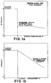
- Figures 1a and 1b present graphs of schematic thermal shock test results, the first graph illustrating the catastrophic decrease in strength exhibited by a material which undergoes rapid crack propagation, and the second graph illustrating the gradual decrease in strength exhibited by a material which undergoes stable crack propogation and which is thus deemed to possess good thermal shock resistance.
- materials which undergo rapid crack propagation are not suited for applications in which they will be exposed to rapid changes in temperature.
- Ceramic materials in general do not have particularly good thermal shock resistance because of theirbrittle nature, and a need exists for methods to improve the thermal shock resistance properties of these valuable materials.
- the present invention relates to a method for the production of high strength sinterable materials, such as ceramics, which exhibit good thermal shock resistance, by extrusion techniques.
- the method according to the invention is applicable both to the production of an article which is sinterable, that is a green body, as well as to a sintered body of high strength formed by firing the green body.
- a method of producing a sinterable extruded laminated article comprising a sinterable extruded laminated body having multiple discrete layers of at least a first and second sinterable material, where said first and second sinterable materials are different and are selected from particulate or powdered materials which are sinterable, and wherein said layers of each of said first and second sinterable materials are substantially uniformly distributed throughout the body comprising the steps of
- the ratio of either of said layers of first or second sintered materials to the other is no greater than about 1.2:1. Generally, however, the ratio of either of said layers of first or second sintered materials to the other may be up to 10:1.
- the term "green” is used in the art and in this application to refer to the state of a formed body or piece made of sinterable powder or particulate material that has not yet been fired to the sintered state.
- the green body may have been heated to dry it by evaporating or volatilizing plasticizing liquid or vehicle and perhaps also to burn out volatile organic or decomposable binders mixed with the sinterable powder to render it adequately plastically formable and/or sufficently coherent (having green strength) so that the body can be handled without deformation and other damage. Firing of the sinterable, green, body to sinter the sinterable materials results in a high strength sintered article.
- Figures 1a and 1b are schematic graphs of typical thermal shock test behaviour.
- Figure 1a illustrates the catastrophic decrease in strength exhibited by a material which undergoes rapid crack propogation
- Figure 1b illustrates the gradual decrease in strength exhibited by a material which undergoes stable crack propagation.
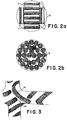
- Figure 2a is a schematic drawing of an end view of an extruder barrel having a typical assembly of composite bodies of first and second sinterable materials loaded therein prior to extrusion.
- Figure 2b is a schematic drawing of an end view of an extruder barrel having a typical assembly of once-extruded composites loaded therein.
- Figure 2c is an illustration of composite body shapes of first and second sinterable materials which can be extruded into a laminated composite article of final desired shape.
- Figure 2d is a schematic drawing of an end view of an extruder barrel having a typical assembly of rods, spheres or slugs loaded therein.
- Figure 2e is a schematic drawing of a cross-sectional side view of an extruder barrel having an assembly of ribbons, sheets or discs layered therein perpendicular to the barrel axis.
- Figure 3 is a schematic of a magnified view of a portion of the walls of a honeycomb structure showing the uniformly distributed layers of first and second sinterable materials.
- Figure 4 is a graph presenting the results of Hasselman thermal shock testing of Examples 1 and 2.
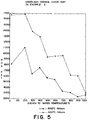
- Figures 5, 6 and 7 are graphs presenting the results of Hasselman thermal shock testing of Examples 3, 4 and 5, respectively.
- the materials from which the extruded laminated articles of this invention are made may be any of the well-known sinterable inorganic materials capable of providing mechanical strength and good thermal properties.
- the materials are ceramic materials, but they may also be selected from cermet, metallic, glass and glass-ceramic materials.
- suitable materials include glasses, such as boro-silicates, soda-lime-silicates, lead-silicates, alumino-silicates, alkaline earth silicates, and fused silica, and oxide ceramics such as alumina, alumina-zirconia, thoria, spinels, titania, urania, rare earth oxides, calcium-aluminates, sillimanite, mullite, magnesia, zirconia, various silicates including cordierite, steatite, petalite, spodumene, fosterite, clay, zircon, talc and porcelain, various nitrides including silicon nitride, silicon oxynitrides, and aluminum nitride, various carbides including silicon carbide, boron carbide, titanium carbide and zirconium carbide, various borides, various zirconates, various titanates, various glass-ceramics, and mixtures or combinations of such materials.
- the sinterable materials may also be selected from glass-ceramics or from sinterable ceramic and metal mixtures, e.g., chromium and alumina mixtures, to form cermets.
- sinterable metal powders e.g., powders of Fe, Al, Cu, Ti, Zr, Ni, Cr, stainless steel, various other alloys and mixtures or combinations thereof. Additional examples of metal powders which can be sintered to form a sintered body are disclosed in U.S. 4,649,003, the disclosure of which is herein incorporated by reference.
- the phases or layers of sinterable materials may optionally contain reinforcing whiskers, e.g., of alumina, silicon nitride or silicon carbide, or fibers, e.g., carbon fibers, as disclosed in U.S. 3,794,707 and U.S. 4,673,658.
- reinforcing whiskers e.g., of alumina, silicon nitride or silicon carbide
- fibers e.g., carbon fibers
- the sinterable particulate or powdered ceramic, glass or glass-ceramic materials used in this invention may also optionally contain substantial amounts of a component which causes intracrystalline and intercrystalline microcracking to occur.
- Ceramic materials which contain such a component, and are therefore contemplated for use within the present invention are disclosed in U.S. Patents 3,528,831, 3,549,400 and 3,578,471, all issued to I. M. Lachman.
- a preferred microcracking agent or addition to the ceramic material is aluminum titanate, which is normally incorporated into a ceramic matrix as a "solid solution" with the basic ceramic material.
- An aluminum titanate solid solution with mullite is disclosed in U.S. Patent 4,483,944 to Day et al. The disclosures of the four above-mentioned patents are incorporated herein by reference.
- the choice of materials from which the articles of this invention will be made is not necessarily critical, and the above-mentioned materials are recited solely for purposes of exemplification.
- the materials of the different laminated phases have differing thermal expansion and firing shrinkage properties to enhance microcracking.
- the sinterable materials of the layers not be reactive with one another to a degree so as to diminish the integrity of the discrete layers in the article.
- the sinterable materials of which each layer in the article is formed are separately formed into moldable bodies by mixing the constituent materials with an additional substance that binds those materials into a plasticized mass.
- This plasticizing/binding agent can be any of the well-known materials commonly used in the ceramic art for such purposes. Suitable plasticizing/binding agents are disclosed in: "Ceramics Processing Before Firing,” ed. by George Y. Onoda, Jr. & L. L. Hench, John Wiley & Sons, New York "Study of Several Groups of Organic Binders Under Low-Pressure Extrusion," C.C. Treischel & E. W. Emrich, Jour. Am. Cer. Soc., (29) pp.
- Preferred agents are methyl cellulose, polyvinyl alcohol or a silicone resin.
- the silicone resins preferred for use are described in U.S. Patent 3,090,691 to Weyer.
- the most preferred binder is methyl cellulose, available as Methocel K75 from the Dow Chemical Company.
- the sinterable particulate or powdered materials are separately mixed with sufficient plasticizing/binding agent to form a moldable mass.
- the mixing step can be performed wet or dry. Intensive mixing such as obtained with a Littleford Mixer is preferred, but other conventional mixing equipment can also be used.
- a liquid, preferably water is added, which acts as a plasticizer.
- the plasticizing/binding agent is a silicone resin, it is preferred to use isopropyl alcohol or equivalent solvent, in addition to water. Plasticizing is attained with the use of a mix muller or other commonly used shearing device.
- plasticized masses of sinterable particulate or powdered material are molded or formed into multiple discrete bodies such as rods, discs, spheres, cylinders, pellets, bars, ribbons or sheets. This is generally done by extrusion methods, but other methods such as tape casting, pressing, pug milling, slip casting and slurry filtering may also be used. See, e.g., Thompson, J.J., "forming Thin Ceramics,” Ceramic Bulletin , Vol. 42, No. 9, page 480 (1963); and U.S. Patents 2,966,719, 3,007,222 and 3,444,925, the disclosures of which are herein incorporated by reference.
- first bodies are then intermingled with bodies of the second sinterable material (“second” bodies) to form an assembly suitable for coextrusion through a die to form a composite laminated article of the desired shape.
- the first and second bodies of sinterable material should be substantially uniformly distributed throughout the assembly and composite article.
- the ratio of either of said bodies to the other will not exceed about 10:1 and more desirably 3:1.
- the ratio of either of said bodies to the other will not exceed about 1.2:1, and, more preferably, the ratio of either of said bodies to the other is about 1:1.
- the size and shape of the first and second bodies of sinterable material be about the same.
- the composite article so formed can be of any size or shape so long as the first and second bodies of sinterable material are substantially uniformly distributed throughout and are present therein in distinct phases and so long as the composite article can be extruded through a die to form the article in its final desired shape.
- the manner of forming the composite article can be of any means by which these criteria are substantially met.
- the first and second bodies of sinterable material can be molded together into a composite article in the shape of a sausage, sphere, bar or disc which is then extruded into the final monolith shape.
- Figure 2c illustrates a bar and a disc of first and second bodies of sinterable material, 1 and 2, respectively. It is also possible, and preferred, to intermingle the bodies directly in the inlet barrel of the extruder, thus forming an assembly which can be immediately extruded thereafter, as shown in Figure 2a.
- Figures 2d and 2e illustrate how different geometrical assemblies can be oriented in the extruder barrel.
- Figure 2d shows how rods, spheres or slugs of first and second sinterable materials, 1 and 2, could be assembled, e.g. by axially stacking in adjacent columns, in the extruder barrel 3 so that, after extrusion, a laminated composite article results.
- Figure 2e shows how discs or sheets 1 and 2 can be layered in the barrel 3 of an extruder so that the plane of the disc is perpendicular to the axis of the extruder. This method of axially stacking will produce a type of laminated extrusion, especially if thin layers are used.
- the plasticized masses of first and second sinterable materials are separately extruded through a die into elongated shapes, preferably of rectangular, hexagonal or circular cross-section.
- the shapes and dimensions thereof are the same for each sinterable material.
- the plasticized sinterable materials are extruded as ribbons approximately 4mm thick by 32 mm wide.
- the extruded composite bodies are then assembled by intermingling the molded components axially or longitudinally. Most preferably, this will be done so that the ribbons are substantially parallel.
- the extruded bodies are positioned to be substantially uniformly distributed throughout the assembly.
- Figure 2a depicts the cross-sectional of an assembly of ribbons of the two phases of materials assembled longitudinally in the barrel, 3, of an extruder.
- First and second bodies of sinterable material, 1 and 2, respectively, are uniformly distributed through the assembly.
- the composite so assembled is then itself preferably extruded through a rod die one or more times to reduce its own cross-sectional area and to effect further distribution of the two phases therein.
- a typical distribution of the composite bodies in a die head or extruder barrel 3 prior to reextrusion is illustrated in Figure 2b.
- the distribution of the phases in the extruded article e.g., the relative thicknesses of the layers, can be controlled not only by the number of extrusions performed but also on the initial size of the first and second bodies used to form the composite. It is convenient that extrusion be performed in a die that reduces the size of the cross-sectional area of the composite itself to that similar to one of the original constituent ribbons.
- the composite is extruded through a die to form the desired shape of the final article.
- the article so extruded is a honeycomb body or multichannel monolith having substantially parallel cells or passages extending between open end faces thereof.
- Typical honeycomb monoliths for example, have 62 square cells per square centimetre (400 square cells per square inch) with a wall thickness of 178 ⁇ m (7 mils), or as another example, have 31 square cells per square centimetre (200 square cells per square inch) with a wall thickness of 508 ⁇ m (20 mils).
- Figure 3 shows an enlarged portion of a honeycomb monolith formed by the extrusion of a composite as described above.
- Layers 1b of a first sinterable material are interspersed with layers 2b of a second sinterable material, and both such layers are substantially uniformly distributed throughout the article and both are substantially discontinuous.
- This is in contrast to the extruded monolithic catalyst supports prepared by extrusion and disclosed in U.S. 4,631,268.
- the articles disclosed therein were prepared by extrusion methods similar to those described above; however, the extrusion was carried out so that, rather than forming laminated phases or layers, one of the sinterable materials, the catalyst-support phase, was embedded in the second sinterable material, a ceramic which formed a substantially continuous matrix phase.
- the extruded shapes are then heated to a temperature and for a time sufficient to sinter the particulate or powdered materials.
- this heating/sintering step is preceded by drying the shapes at about 100° - 120°C. It is then preferred to burn out the temporary binders in the range of 250° - 500°C.
- the heating/sintering step generally takes place above 800°C, although when silicone resin is used as a binder for the ceramic matrix, temperatures as low as 500°C may be sufficient.
- the maximum firing temperature is limited by the melting points of the constituents in the compositions.
- test results were obtained using the following: Flexural Strength - ASTM Test No. C-158-84 Thermal Expansion - ASTM Test No. E831-81 Modulus of Elasticity - ASTM Test No. C326-82 Bulk Density - Volume computed from measurements of the physical dimensions of a bar and weighed dry for final computation of the bulk density.
- the dry powders were mixed in a Model M5G Littleford dry blender for three minutes.
- the Model M5G is a plow oriented blender which thoroughly mixes the powders without changing particle size or increasing batch temperature due to friction.
- Methylcellulose (Dow K75, 4% in Examples 1 and 2, 6% in Examples 3, 4 and 5), a temporary binder, and, in Examples 1 and 2, 1% sodium stearate lubricant were mixed with the other dry materials.
- compositions were wet mulled using a Lancaster counter current batch mixture type PC. Water was introduced during this process and all batches were mulled between 15 to 20 minutes for good plasticity and homogeneity of the materials. After mulling, the batch consistency had an appearance of crumbs to small, flat chunks that were somewhat soft and plastic.
- Shapes extruded for this study included 8 mm rods for firing shrinkage, flexural strength, axial thermal expansion, mercury porosity and Hasselman thermal shock testing; 5 mm x 15 mm bars for modulus of elasticity measurements; 2.54 cms (1") diameter, 62 cells/cm2 (400 cells/in2) honeycomb for laboratory thermal shock testing and evaluation.
- Example 2 The data in Table 2 indicate that, in the case of the calcium-aluminate laminated composition, Example 1, the firing shrinkage is actually an expansion (+2.5% @1600°C), resulting in very low strengths (12411 kPa (1800 psi) @ 1600°C).
- Example 2 the extruded laminated composition with alumina and zirconia, has higher strengths (41370 kPa (6000 psi) @ 1600°C) but also higher axial thermal expansion (81.0 x 10 ⁇ 7 @ 1600°C).
- Example 1 and 2 were also tested for thermal shock resistance using the Hasselman test. Samples previously fired at 1600°C for six hours were chosen for the test. The dimensions of the test samples were 0.635 cm (1/4") diameter x 10.16 cms (4") long, and they were tested over a range of quench temperatures, 200°C to 1000°C, at 100° increments. Four rods were used at each quench temperature with a new set of rods being used at each succeeding temperature. Samples were held at temperature for fifteen minutes and then quenched in cold water. Tested rods were then dried and submitted for room temperature modulus of rupture. The strength results for the thermal shock tested samples are shown in Figure 4. As these data indicate, the material of Example 2 has good thermal shock resistance because of its rather stable crack propagation. The material of Example 1 is much weaker and displays signs of being less stable.
- Axial thermal expansion was in the range of 60 - 70 x 10 ⁇ 7 @ 1000°C for all the compositions of all three examples.
- the laminated layers of the mullite extruded laminated series of Examples 3 - 5 fired at both 1500°C and 1650°C are very distinctive in photomicrographs of the articles.
- the Hasselman thermal shock test was conducted on the laminated extruded rods of Examples 3 - 5 which had been fired at both 1500°C and 1650°C for 6 hours. The results are graphically illustrated in Figures 5, 6 and 7 and make apparent the differences between the 1500°C and 1650°C firings. Good strength remains at the lower end of the test quench temperature (200-400°C) and then a general decrease in strength with increasing quench temperature. Although the strength decrease is substantial over the whole range of the Hasselman thermal shock test, the results appear to indicate stable rather than catastrophic crack propagation.
Landscapes
- Engineering & Computer Science (AREA)
- Chemical & Material Sciences (AREA)
- Ceramic Engineering (AREA)
- Manufacturing & Machinery (AREA)
- Materials Engineering (AREA)
- Structural Engineering (AREA)
- Organic Chemistry (AREA)
- Life Sciences & Earth Sciences (AREA)
- Wood Science & Technology (AREA)
- Compositions Of Oxide Ceramics (AREA)
- Laminated Bodies (AREA)
- Press-Shaping Or Shaping Using Conveyers (AREA)
Description
- This invention relates to a method for the Production of laminated extruded thermal shock resistant articles formed from sinterable particulate or powdered materials.
- Due to properties such as high strength, temperature and chemical stability, and electrical and thermal insulating properties, ceramics are widely used engineering materials. In many applications, such as cookware, spark plug insulators, abrasive wheels, refractory linings, applications in the chemical process industries, heat exchangers, and high temperature automotive substrates, ceramic materials can be exposed to rapid changes in temperature or large thermal gradients. To be useful, the materials should desirably exhibit good thermal shock resistance, i.e., must maintain their strength after thermal shocking.
- Thermal shock resistance is usually measured by quenching from a high temperature and by measuring the strength degradation (as compared to measurements made on samples not yet subjected to thermal shock). A commonly used test for thermal shock resistance is that described by Hasselman. See, e.g., Hasselman, "Strength Behavior of Polycrystalline Alumina Subjected to Thermal Shock," J. Am. Ceramic Soc., Vol. 53, No. 9, pp. 490-495, Sept. 1970, and Larson and Hasselman, "Comparative Behavior of High-Alumina Refractories Subjected to Sudden Heating and Cooling", Transactions and Journal of the British Ceramic Society, (74) No. 2, pp. 59-65, March/April 1975. It is recognized that all ceramic materials, as they are quenched from successively higher temperatures, will undergo cracking and exhibit strength degradation. Preferably, the ceramic materials will, upon being quenched from successively higher temperatures, exhibit stable crack propagation and, thus, a gradual and predictable decrease in strength. For the purpose of this invention, materials exhibiting such properties are deemed to exhibit good thermal shock resistance. There are ceramic materials, however, which undergo rapid crack propagation after quenching from a certain temperature and exhibit what is termed a "catastrophic" decrease in strength. Figures 1a and 1b present graphs of schematic thermal shock test results, the first graph illustrating the catastrophic decrease in strength exhibited by a material which undergoes rapid crack propagation, and the second graph illustrating the gradual decrease in strength exhibited by a material which undergoes stable crack propogation and which is thus deemed to possess good thermal shock resistance. Clearly, materials which undergo rapid crack propagation are not suited for applications in which they will be exposed to rapid changes in temperature.
- Ceramic materials in general do not have particularly good thermal shock resistance because of theirbrittle nature, and a need exists for methods to improve the thermal shock resistance properties of these valuable materials.
- In J. Am. Ceramic Soc., Communications of the American Ceramic Society, vol. 69, no. 8, August 1986, pages C-191-C-192, Columbus, Ohio, US; P. Boch et al.: "Tape casting of Al₂0₃/Zr0₂ laminated composites" there are described high strength articles comprising a sintered laminated body having multiple discrete layers of at least a first and second sintered material, where said first and second sintered materials are different and are selected from particulate or powdered materials which have been sintered to high strength materials, and wherein said layers of each of said first and second sintered materials are substantially uniformly distributed throughout the body.
- The present invention relates to a method for the production of high strength sinterable materials, such as ceramics, which exhibit good thermal shock resistance, by extrusion techniques. The method according to the invention is applicable both to the production of an article which is sinterable, that is a green body, as well as to a sintered body of high strength formed by firing the green body.
- According to the invention there is provided a method of producing a sinterable extruded laminated article comprising a sinterable extruded laminated body having multiple discrete layers of at least a first and second sinterable material, where said first and second sinterable materials are different and are selected from particulate or powdered materials which are sinterable, and wherein said layers of each of said first and second sinterable materials are substantially uniformly distributed throughout the body comprising the steps of
- (a) providing first multiple bodies comprising a mixture of said first sinterable materials and a plasticizing/bonding agent for said material;
- (b) providing second multiple bodies comprising a mixture of said second sinterable material and a plasticizing/bonding agent for said material;
- (c) intermingling said first and second multiple bodies to form an assembly thereof wherein said first and second multiple bodies are substantially uniformly distributed throughout said assembly ; and
- (d) passing said assembled body through a die to form said sinterable extruded laminated composite article in a desired shape.
- In the preferred embodiment of the invention, the ratio of either of said layers of first or second sintered materials to the other is no greater than about 1.2:1. Generally, however, the ratio of either of said layers of first or second sintered materials to the other may be up to 10:1.
- In relation to the production of the green body, the term "green" is used in the art and in this application to refer to the state of a formed body or piece made of sinterable powder or particulate material that has not yet been fired to the sintered state. The green body may have been heated to dry it by evaporating or volatilizing plasticizing liquid or vehicle and perhaps also to burn out volatile organic or decomposable binders mixed with the sinterable powder to render it adequately plastically formable and/or sufficently coherent (having green strength) so that the body can be handled without deformation and other damage. Firing of the sinterable, green, body to sinter the sinterable materials results in a high strength sintered article.
- Tests indicate that the sintered articles made according to the invention exhibit good thermal shock resistance. It is believed that this good thermal shock resistance is the result of several factors. First, the presence of the discontinuities in the sintered article resulting from the presence of a plurality of phases is believed to prevent crack growth and relieve stresses. Second, it is known that microcracking enhances the thermal shock resistance of an article based on ceramics by lowering the modulus of elasticity of the article. Microcracking is encouraged when the materials in the different phases in the articles of this invention possess different thermal expansions and firing shrinkages. Third, the plurality of phases arranged in a laminated fashion results in each of the phases being substantially discontinuous.
- Figures 1a and 1b are schematic graphs of typical thermal shock test behaviour. Figure 1a illustrates the catastrophic decrease in strength exhibited by a material which undergoes rapid crack propogation, and Figure 1b illustrates the gradual decrease in strength exhibited by a material which undergoes stable crack propagation.
- Figure 2a is a schematic drawing of an end view of an extruder barrel having a typical assembly of composite bodies of first and second sinterable materials loaded therein prior to extrusion.
- Figure 2b is a schematic drawing of an end view of an extruder barrel having a typical assembly of once-extruded composites loaded therein.
- Figure 2c is an illustration of composite body shapes of first and second sinterable materials which can be extruded into a laminated composite article of final desired shape.
- Figure 2d is a schematic drawing of an end view of an extruder barrel having a typical assembly of rods, spheres or slugs loaded therein.
- Figure 2e is a schematic drawing of a cross-sectional side view of an extruder barrel having an assembly of ribbons, sheets or discs layered therein perpendicular to the barrel axis.
- Figure 3 is a schematic of a magnified view of a portion of the walls of a honeycomb structure showing the uniformly distributed layers of first and second sinterable materials.
- Figure 4 is a graph presenting the results of Hasselman thermal shock testing of Examples 1 and 2.
- Figures 5, 6 and 7 are graphs presenting the results of Hasselman thermal shock testing of Examples 3, 4 and 5, respectively.
- The materials from which the extruded laminated articles of this invention are made may be any of the well-known sinterable inorganic materials capable of providing mechanical strength and good thermal properties. In the preferred embodiment, the materials are ceramic materials, but they may also be selected from cermet, metallic, glass and glass-ceramic materials.
- Reference to suitable sinterable materials which can be used in this invention is made in U.S. Patents 3,112,184, 3,444,925, 3,824,196, 3,885,977, 3,919,384, 3,963,504, 4,017,347 and 4,582,677, the disclosures of which are herein incorporated by reference. Examples of suitable materials include glasses, such as boro-silicates, soda-lime-silicates, lead-silicates, alumino-silicates, alkaline earth silicates, and fused silica, and oxide ceramics such as alumina, alumina-zirconia, thoria, spinels, titania, urania, rare earth oxides, calcium-aluminates, sillimanite, mullite, magnesia, zirconia, various silicates including cordierite, steatite, petalite, spodumene, fosterite, clay, zircon, talc and porcelain, various nitrides including silicon nitride, silicon oxynitrides, and aluminum nitride, various carbides including silicon carbide, boron carbide, titanium carbide and zirconium carbide, various borides, various zirconates, various titanates, various glass-ceramics, and mixtures or combinations of such materials.
- The sinterable materials may also be selected from glass-ceramics or from sinterable ceramic and metal mixtures, e.g., chromium and alumina mixtures, to form cermets. Also suitable are sinterable metal powders, e.g., powders of Fe, Al, Cu, Ti, Zr, Ni, Cr, stainless steel, various other alloys and mixtures or combinations thereof. Additional examples of metal powders which can be sintered to form a sintered body are disclosed in U.S. 4,649,003, the disclosure of which is herein incorporated by reference.
- The phases or layers of sinterable materials may optionally contain reinforcing whiskers, e.g., of alumina, silicon nitride or silicon carbide, or fibers, e.g., carbon fibers, as disclosed in U.S. 3,794,707 and U.S. 4,673,658.
- The sinterable particulate or powdered ceramic, glass or glass-ceramic materials used in this invention may also optionally contain substantial amounts of a component which causes intracrystalline and intercrystalline microcracking to occur. Ceramic materials which contain such a component, and are therefore contemplated for use within the present invention, are disclosed in U.S. Patents 3,528,831, 3,549,400 and 3,578,471, all issued to I. M. Lachman. A preferred microcracking agent or addition to the ceramic material is aluminum titanate, which is normally incorporated into a ceramic matrix as a "solid solution" with the basic ceramic material. An aluminum titanate solid solution with mullite is disclosed in U.S. Patent 4,483,944 to Day et al. The disclosures of the four above-mentioned patents are incorporated herein by reference.
- The choice of materials from which the articles of this invention will be made is not necessarily critical, and the above-mentioned materials are recited solely for purposes of exemplification. As has been previously noted, it is preferred that the materials of the different laminated phases have differing thermal expansion and firing shrinkage properties to enhance microcracking. Naturally, it is also preferred that the sinterable materials of the layers not be reactive with one another to a degree so as to diminish the integrity of the discrete layers in the article.
- The choice of material will also, of course, depend upon the intended application of the article. For example, the chemical resistance of the materials is a concern when the ultimate articles are intended for use in certain chemical processing application, e.g., silicon-based materials might be avoided in chemical processes utilizing reducing gases.
- The sinterable materials of which each layer in the article is formed are separately formed into moldable bodies by mixing the constituent materials with an additional substance that binds those materials into a plasticized mass. This plasticizing/binding agent, can be any of the well-known materials commonly used in the ceramic art for such purposes. Suitable plasticizing/binding agents are disclosed in:
"Ceramics Processing Before Firing," ed. by George Y. Onoda, Jr. & L. L. Hench, John Wiley & Sons, New York
"Study of Several Groups of Organic Binders Under Low-Pressure Extrusion," C.C. Treischel & E. W. Emrich, Jour. Am. Cer. Soc., (29) pp. 129-132, 1946
"Organic (Temporary) Binders for Ceramic Systems," S. Levine, Ceramic Age, (75) No. 1, pp. 39+, January 1960
"Temporary Organic Binders for Ceramic Systems," S. Levine, Ceramic Age, (75) No. 2, pp. 25+, February 1960. - Preferred agents are methyl cellulose, polyvinyl alcohol or a silicone resin. The silicone resins preferred for use are described in U.S. Patent 3,090,691 to Weyer. The most preferred binder is methyl cellulose, available as Methocel K75 from the Dow Chemical Company.
- The sinterable particulate or powdered materials are separately mixed with sufficient plasticizing/binding agent to form a moldable mass. Generally, about 1-20 percent by weight, based on the sinterable particulate or powdered material weight, of the plasticizing/binding agent is used. Up to about 1 percent by weight, based upon the total body weight, of surfactant or lubricant such as sodium stearate can also be used to facilitate mixing and extruding. The mixing step can be performed wet or dry. Intensive mixing such as obtained with a Littleford Mixer is preferred, but other conventional mixing equipment can also be used. At some point in the fabrication process, usually after dry mixing, a liquid, preferably water, is added, which acts as a plasticizer. When the plasticizing/binding agent is a silicone resin, it is preferred to use isopropyl alcohol or equivalent solvent, in addition to water. Plasticizing is attained with the use of a mix muller or other commonly used shearing device.
- The plasticized masses of sinterable particulate or powdered material are molded or formed into multiple discrete bodies such as rods, discs, spheres, cylinders, pellets, bars, ribbons or sheets. This is generally done by extrusion methods, but other methods such as tape casting, pressing, pug milling, slip casting and slurry filtering may also be used. See, e.g., Thompson, J.J., "forming Thin Ceramics," Ceramic Bulletin, Vol. 42, No. 9, page 480 (1963); and U.S. Patents 2,966,719, 3,007,222 and 3,444,925, the disclosures of which are herein incorporated by reference. Such bodies of the first sinterable material ("first" bodies) are then intermingled with bodies of the second sinterable material ("second" bodies) to form an assembly suitable for coextrusion through a die to form a composite laminated article of the desired shape. The first and second bodies of sinterable material should be substantially uniformly distributed throughout the assembly and composite article. Generally it is useful that the ratio of either of said bodies to the other will not exceed about 10:1 and more desirably 3:1. Preferably, the ratio of either of said bodies to the other will not exceed about 1.2:1, and, more preferably, the ratio of either of said bodies to the other is about 1:1. It is preferred that the size and shape of the first and second bodies of sinterable material be about the same.
- The composite article so formed can be of any size or shape so long as the first and second bodies of sinterable material are substantially uniformly distributed throughout and are present therein in distinct phases and so long as the composite article can be extruded through a die to form the article in its final desired shape. It is also to be understood that the manner of forming the composite article can be of any means by which these criteria are substantially met. For example, the first and second bodies of sinterable material can be molded together into a composite article in the shape of a sausage, sphere, bar or disc which is then extruded into the final monolith shape. Figure 2c illustrates a bar and a disc of first and second bodies of sinterable material, 1 and 2, respectively. It is also possible, and preferred, to intermingle the bodies directly in the inlet barrel of the extruder, thus forming an assembly which can be immediately extruded thereafter, as shown in Figure 2a.
- Figures 2d and 2e illustrate how different geometrical assemblies can be oriented in the extruder barrel. Figure 2d shows how rods, spheres or slugs of first and second sinterable materials, 1 and 2, could be assembled, e.g. by axially stacking in adjacent columns, in the
extruder barrel 3 so that, after extrusion, a laminated composite article results. Figure 2e shows how discs orsheets barrel 3 of an extruder so that the plane of the disc is perpendicular to the axis of the extruder. This method of axially stacking will produce a type of laminated extrusion, especially if thin layers are used. - In a preferred embodiment of the present invention, the plasticized masses of first and second sinterable materials are separately extruded through a die into elongated shapes, preferably of rectangular, hexagonal or circular cross-section. Preferably, the shapes and dimensions thereof are the same for each sinterable material. Also preferably, the plasticized sinterable materials are extruded as ribbons approximately 4mm thick by 32 mm wide.
- The extruded composite bodies are then assembled by intermingling the molded components axially or longitudinally. Most preferably, this will be done so that the ribbons are substantially parallel. The extruded bodies are positioned to be substantially uniformly distributed throughout the assembly. As an example, Figure 2a depicts the cross-sectional of an assembly of ribbons of the two phases of materials assembled longitudinally in the barrel, 3, of an extruder. First and second bodies of sinterable material, 1 and 2, respectively, are uniformly distributed through the assembly.
- The composite so assembled is then itself preferably extruded through a rod die one or more times to reduce its own cross-sectional area and to effect further distribution of the two phases therein. A typical distribution of the composite bodies in a die head or
extruder barrel 3 prior to reextrusion is illustrated in Figure 2b. The distribution of the phases in the extruded article, e.g., the relative thicknesses of the layers, can be controlled not only by the number of extrusions performed but also on the initial size of the first and second bodies used to form the composite. It is convenient that extrusion be performed in a die that reduces the size of the cross-sectional area of the composite itself to that similar to one of the original constituent ribbons. - Ultimately, the composite is extruded through a die to form the desired shape of the final article. In one embodiment of the invention, the article so extruded is a honeycomb body or multichannel monolith having substantially parallel cells or passages extending between open end faces thereof. Typical honeycomb monoliths, for example, have 62 square cells per square centimetre (400 square cells per square inch) with a wall thickness of 178 µm (7 mils), or as another example, have 31 square cells per square centimetre (200 square cells per square inch) with a wall thickness of 508 µm (20 mils). Figure 3 shows an enlarged portion of a honeycomb monolith formed by the extrusion of a composite as described above. Layers 1b of a first sinterable material are interspersed with
layers 2b of a second sinterable material, and both such layers are substantially uniformly distributed throughout the article and both are substantially discontinuous. This is in contrast to the extruded monolithic catalyst supports prepared by extrusion and disclosed in U.S. 4,631,268. The articles disclosed therein were prepared by extrusion methods similar to those described above; however, the extrusion was carried out so that, rather than forming laminated phases or layers, one of the sinterable materials, the catalyst-support phase, was embedded in the second sinterable material, a ceramic which formed a substantially continuous matrix phase. - Although the above description was limited to the preparation of an article having discrete phases of two sinterable materials, this invention is not intended to be so limited. Three or more sinterable material may be combined using the general methods outlined above to form extruded laminated bodies according to this invention. In all cases, it is preferred that the varieties of sinterable materials be substantially uniformly distributed throughout the final article.
- The extruded shapes are then heated to a temperature and for a time sufficient to sinter the particulate or powdered materials. Optionally, this heating/sintering step is preceded by drying the shapes at about 100° - 120°C. It is then preferred to burn out the temporary binders in the range of 250° - 500°C. The heating/sintering step generally takes place above 800°C, although when silicone resin is used as a binder for the ceramic matrix, temperatures as low as 500°C may be sufficient. The maximum firing temperature is limited by the melting points of the constituents in the compositions.
- Aspects of this invention are illustrated, but not limited by, the following examples. In these examples, test results were obtained using the following:
Flexural Strength - ASTM Test No. C-158-84
Thermal Expansion - ASTM Test No. E831-81
Modulus of Elasticity - ASTM Test No. C326-82
Bulk Density - Volume computed from measurements of the physical dimensions of a bar and weighed dry for final computation of the bulk density. - Five laminated extruded articles were made according to this invention using the materials as set forth in Table 1. In each example, equal amounts of components A and B were used to prepare the extruded articles.
Table 1 Example Component A Component B 1 62.9% alumina 96.0% alumina 37.1% calcium carbonate 2.7% manganese 1.3 % titania 2 100% alumina* 77.0% alumina 19.0% zirconia 2.7% manganese carbonate 1.3 % titania 3 50.0% alumina 96.0% alumina 40.0% calcined clay 2.7% manganese carbonate 10/0% kaolin clay 1.8 % titania 4 50.0% alumina 87.0% alumina 40.0% calcined clay 9.0% zirconia 10.0% kaolin clay 2.7% manganese carbonate 1.3 % titania 5 50.0% alumina 77.0% alumina 40.0% calcined clay 19.0% zirconia 10.0% kaolin clay 2.7% manganese carbonate 1.3% titania Baker reagent calcium carbonate #1294
Fisher manganese carbonate M-85
Baker reagent titania #4162
Zircoa A-grain zirconia
Georgia-Kaolin Glomax-LL calcined kaolin clay
Georgia-Kaolin Hydrite-MP kaolin clay*Alcoa T-61 -325 mesh; all other aluminas Alcan C-701 RGE - In each example, the dry powders were mixed in a Model M5G Littleford dry blender for three minutes. The Model M5G is a plow oriented blender which thoroughly mixes the powders without changing particle size or increasing batch temperature due to friction. Methylcellulose (Dow K75, 4% in Examples 1 and 2, 6% in Examples 3, 4 and 5), a temporary binder, and, in Examples 1 and 2, 1% sodium stearate lubricant were mixed with the other dry materials.
- All compositions were wet mulled using a Lancaster counter current batch mixture type PC. Water was introduced during this process and all batches were mulled between 15 to 20 minutes for good plasticity and homogeneity of the materials. After mulling, the batch consistency had an appearance of crumbs to small, flat chunks that were somewhat soft and plastic.
- Extrusion of the samples were conducted on a 20 ton Wahlco extrusion press with a barrel diameter of 6.670 cms (2.626") and maximum hydraulic pressure of 17,237 kPa (2500 psi). The fabrication process was a multi-step procedure. It involved extruding two separate compositions in the form of
ribbon 4 mm thick by 32 mm wide (0.157" x 1.25"). This ribbon was then alternately stacked in the barrel of the extruder and pushed into an intermediate shape of a 5.2 mm rod (.205" diameter). With a successive extrusion, the laminations could be reduced to a desired thickness. Shapes extruded for this study included 8 mm rods for firing shrinkage, flexural strength, axial thermal expansion, mercury porosity and Hasselman thermal shock testing; 5 mm x 15 mm bars for modulus of elasticity measurements; 2.54 cms (1") diameter, 62 cells/cm² (400 cells/in²) honeycomb for laboratory thermal shock testing and evaluation. - All samples were dried in a steam-like atmosphere at 100°C for three days and then fired in a Bickley gas-air furnace at the various designated temperatures.
- Physical property results for shrinkage, strength and thermal expansion for each component of the laminated articles of Examples 1 and 2 and for the laminated articles themselves are presented in Table 2.
Table 2 Firing Temp.°C 6hrs. % Shrink Flexural Str., kPa (psi) Thermal Exp.* Example 1 1500 -4.4 12204 (1770) 62.4 1600 -2.5 12479 (1810) 64.6 1650 -1.7 17927 (2600) 64.6 Component A 1500 4.5 34612 (5020) 55.8 1600 1650 16.1 22.6** Component B 1500 1600 17.1 135831 (19700) 1650 17.2 105493 (15300) 80 Example 2 1400 1500 11.9 77913 (11300) 80.5 1600 12.3 41714 (6050) 81.0 1650 12.5 48265 (7000) 80.5 Component A 1400 1.6 23443 (3400) 1500 4.2 55160 (8000) 1600 6.4 68950 (10000) 80 Component B 1400 15.7 104,804 (15200) 81.4 1500 17.1 42749 (6200) 79.4 1600 16.9 29648 (4300) 80.0 1650 16.7 24822 (3600) 78.1 * cm./cm./°C, (25°C-1000°C) **Sample @ 1650°C began to melt. - The data in Table 2 indicate that, in the case of the calcium-aluminate laminated composition, Example 1, the firing shrinkage is actually an expansion (+2.5% @1600°C), resulting in very low strengths (12411 kPa (1800 psi) @ 1600°C). Example 2, the extruded laminated composition with alumina and zirconia, has higher strengths (41370 kPa (6000 psi) @ 1600°C) but also higher axial thermal expansion (81.0 x 10⁻⁷ @ 1600°C).
- The samples of Example 1 and 2 were also tested for thermal shock resistance using the Hasselman test. Samples previously fired at 1600°C for six hours were chosen for the test. The dimensions of the test samples were 0.635 cm (1/4") diameter x 10.16 cms (4") long, and they were tested over a range of quench temperatures, 200°C to 1000°C, at 100° increments. Four rods were used at each quench temperature with a new set of rods being used at each succeeding temperature. Samples were held at temperature for fifteen minutes and then quenched in cold water. Tested rods were then dried and submitted for room temperature modulus of rupture. The strength results for the thermal shock tested samples are shown in Figure 4. As these data indicate, the material of Example 2 has good thermal shock resistance because of its rather stable crack propagation. The material of Example 1 is much weaker and displays signs of being less stable.
- Physical property results for shrinkage, strength and thermal expansion for each component of the laminated articles of Examples 3, 4 and 5 and for the laminated articles themselves are presented in Table 3.

- Axial thermal expansion was in the range of 60 - 70 x 10⁻⁷ @ 1000°C for all the compositions of all three examples. The laminated layers of the mullite extruded laminated series of Examples 3 - 5 fired at both 1500°C and 1650°C are very distinctive in photomicrographs of the articles.
- "As fired" (@ 1600°C) modulus of rupture measurements were performed for the articles of Examples 3 - 5. The results are presented in Table 4 and indicate that strengths increase with the increasing percent of zirconia.
Table 4 Example Room Temp. MOR, kPa (psi) % ZrO₂ 3 10342 (1500) 0 4 128247 (18600) 9 5 188923 (27400) 19 - Modulus of elasticity measurements were conducted on fired bars (0.279 cm (.110") thick x 1.206 cms (.475") wide x 12.7 cms (5.0") long) for the compositions of Examples 2 - 5, the composition of Example 1 being too weak to test. The results, in Table 5, show rather low values indicating that microcracking has occurred. It is estimated that the examples in Table 5 would have room temperature modulus of elasticity values of 27.56 x 10⁶ kPa (40x 10⁶ psi) or more if there were no microcracking. The results also indicate that for the mullite-alumina series (Examples 3-5) a gradual decrease in modulus of elasticity occurred as the amount of zirconia increased, with a much lower reading for the alumina laminated sample. It is believed that increasing zirconia content would increase microcracking, thereby lowering the modulus of elasticity.
Table 5 Example Modulus of Elasticity, kPa (psi) Bulk Density, g/ cm³ 2 81.43 (11.81) 3.661 3 181.1 (26.26) 3.018 4 162.8 (23.62) 3.112 5 158.2 (22.95) 3.103 - The Hasselman thermal shock test was conducted on the laminated extruded rods of Examples 3 - 5 which had been fired at both 1500°C and 1650°C for 6 hours. The results are graphically illustrated in Figures 5, 6 and 7 and make apparent the differences between the 1500°C and 1650°C firings. Good strength remains at the lower end of the test quench temperature (200-400°C) and then a general decrease in strength with increasing quench temperature. Although the strength decrease is substantial over the whole range of the Hasselman thermal shock test, the results appear to indicate stable rather than catastrophic crack propagation.
Claims (8)
- A method of producing a sinterable extruded laminated article comprising a sinterable extruded laminated body having multiple discrete layers of at least a first and second sinterable material, where said first and second sinterable materials are different and are selected from particulate or powdered materials which are sinterable, and wherein said layers of each of said first and second sinterable materials are substantially uniformly distributed throughout the body comprising the steps of(a) providing first multiple bodies comprising a mixture of said first sinterable materials and a plasticizing/bonding agent for said material;(b) providing second multiple bodies comprising a mixture of said second sinterable material and a plasticizing/bonding agent for said material;(c) intermingling said first and second multiple bodies to form an assembly thereof wherein said first and second multiple bodies are substantially uniformly distributed throughout said assembly; and(d) passing said assembled body through a die to form said sinterable extruded laminated composite article in a desired shape.
- A method as claimed in claim 1 wherein a plurality of said sinterable extruded laminated composite articles are intermingled and reextruded by being passed through a die to form a second sinterable extruded laminate composite article in a desired shape.
- A method as claimed in claim 2 wherein said reextrusion step is repeated.
- A method as claimed in any of claims 1 to 3 wherein said sinterable extruded laminated article is fired to sinter the sinterable materials and produce a high strength article.
- A method as claimed in any of claims 1 to 4 wherein the ratio of either of said first or second materials to the other is no greater than about 1.2:1.
- A method as claimed in claim 5 wherein the ratio of either of said first or second sinterable materials to the other is about 1:1.
- A method as claimed in any of claims 1 to 6 wherein said first or second sinterable materials are independently selected from the group consisting of ceramics, glass-ceramics, glasses, cermets, metals, and mixtures and combinations thereof.
- A method as claimed in claim 7 wherein said first and second sinterable materials have different firing shrinkages.
Applications Claiming Priority (2)
| Application Number | Priority Date | Filing Date | Title |
|---|---|---|---|
| US07/170,783 US5053092A (en) | 1988-03-21 | 1988-03-21 | Method for producing a sinterable extruded laminated article |
| US170783 | 1988-03-21 |
Publications (3)
| Publication Number | Publication Date |
|---|---|
| EP0333957A2 EP0333957A2 (en) | 1989-09-27 |
| EP0333957A3 EP0333957A3 (en) | 1990-09-05 |
| EP0333957B1 true EP0333957B1 (en) | 1994-08-03 |
Family
ID=22621234
Family Applications (1)
| Application Number | Title | Priority Date | Filing Date |
|---|---|---|---|
| EP88311243A Expired - Lifetime EP0333957B1 (en) | 1988-03-21 | 1988-11-28 | Laminated extruded thermal shock resistant articles and method for making such articles |
Country Status (6)
| Country | Link |
|---|---|
| US (1) | US5053092A (en) |
| EP (1) | EP0333957B1 (en) |
| JP (1) | JP2791486B2 (en) |
| KR (1) | KR970001181B1 (en) |
| CA (1) | CA1332499C (en) |
| DE (1) | DE3850959T2 (en) |
Families Citing this family (32)
| Publication number | Priority date | Publication date | Assignee | Title |
|---|---|---|---|---|
| US5741842A (en) * | 1991-07-10 | 1998-04-21 | Bayer Aktiengesellschaft | Thermoplastic moulding compounds, a process for their preparation and a process for the production of ceramic or metal moulded parts by sintering |
| US5382396A (en) * | 1992-06-15 | 1995-01-17 | Industrial Technology Research Institute | Method of making a porous ceramic filter |
| JPH06236819A (en) * | 1993-01-11 | 1994-08-23 | Boam R & D Co Ltd | Ferrite magnetic material chip bead structure and its preparation |
| US5308556A (en) * | 1993-02-23 | 1994-05-03 | Corning Incorporated | Method of making extrusion dies from powders |
| IT1260928B (en) * | 1993-07-16 | 1996-04-29 | Fiat Auto Spa | PROCEDURE FOR THE REALIZATION OF METAL AND / OR CERAMIC SHEETS THROUGH SINTERING OF DUST AND RELATED PRODUCT. |
| US5645781A (en) * | 1994-09-21 | 1997-07-08 | The Regents Of The University Of Michigan | Process for preparing textured ceramic composites |
| US5492883A (en) * | 1994-11-21 | 1996-02-20 | Corning Incorporated | Molecular sieve structures using aqueous emulsions |
| US5813872A (en) * | 1996-03-06 | 1998-09-29 | Cooper Technologies Company | Automotive spark plug cover |
| US6479129B1 (en) | 1999-02-18 | 2002-11-12 | Corning Incorporated | Titanium-coating silica glass honeycomb structure from silica soot extrusion |
| KR20010102213A (en) | 1999-02-18 | 2001-11-15 | 알프레드 엘. 미첼슨 | Method of making silica glass honeycomb structure from silica soot extrusion |
| US6709737B2 (en) * | 2000-12-04 | 2004-03-23 | Advanced Ceramics Research, Inc. | Aligned composite structures for mitigation of impact damage and resistance to wear in dynamic environments |
| US6847699B2 (en) | 2000-12-04 | 2005-01-25 | Advanced Ceramics Research, Inc. | Composite components for use in high temperature applications |
| US6803003B2 (en) * | 2000-12-04 | 2004-10-12 | Advanced Ceramics Research, Inc. | Compositions and methods for preparing multiple-component composite materials |
| US6974624B2 (en) * | 2000-12-04 | 2005-12-13 | Advanced Ceramics Research, Inc. | Aligned composite structures for mitigation of impact damage and resistance to wear in dynamic environments |
| US6805946B2 (en) | 2000-12-04 | 2004-10-19 | Advanced Ceramics Research, Inc. | Multi-functional composite structures |
| US6797220B2 (en) * | 2000-12-04 | 2004-09-28 | Advanced Ceramics Research, Inc. | Methods for preparation of three-dimensional bodies |
| US6740286B2 (en) * | 2000-12-04 | 2004-05-25 | Advanced Ceramics Research, Inc. | Consolidation and densification methods for fibrous monolith processing |
| WO2002052579A1 (en) * | 2000-12-22 | 2002-07-04 | Koninklijke Philips Electronics N.V. | A method for producing a grid structure |
| US20050082726A1 (en) * | 2001-05-25 | 2005-04-21 | Advanced Ceramics Research Inc | Ceramic components having multilayered architectures and processes for manufacturing the same |
| US20070152364A1 (en) | 2005-11-16 | 2007-07-05 | Bilal Zuberi | Process for extruding a porous substrate |
| US20070107396A1 (en) * | 2005-11-16 | 2007-05-17 | Bilal Zuberi | Method and apparatus for a gas-liquid separator |
| US8038759B2 (en) | 2005-11-16 | 2011-10-18 | Geoz Technologies, Inc. | Fibrous cordierite materials |
| US7938877B2 (en) | 2005-11-16 | 2011-05-10 | Geo2 Technologies, Inc. | Low coefficient of thermal expansion materials including modified aluminosilicate fibers and methods of manufacture |
| US7959704B2 (en) * | 2005-11-16 | 2011-06-14 | Geo2 Technologies, Inc. | Fibrous aluminum titanate substrates and methods of forming the same |
| KR20080068114A (en) * | 2005-11-16 | 2008-07-22 | 지이오2 테크놀로지스 인코포레이티드 | Extrusion System of Porous Substrate |
| US7938876B2 (en) | 2005-11-16 | 2011-05-10 | GE02 Technologies, Inc. | Low coefficient of thermal expansion materials including nonstoichiometric cordierite fibers and methods of manufacture |
| US7640732B2 (en) | 2005-11-16 | 2010-01-05 | Geo2 Technologies, Inc. | Method and apparatus for filtration of a two-stroke engine exhaust |
| US8039050B2 (en) | 2005-12-21 | 2011-10-18 | Geo2 Technologies, Inc. | Method and apparatus for strengthening a porous substrate |
| US7781372B2 (en) | 2007-07-31 | 2010-08-24 | GE02 Technologies, Inc. | Fiber-based ceramic substrate and method of fabricating the same |
| DE102007027319A1 (en) * | 2007-06-14 | 2008-12-18 | Beru Ag | Spark plug and method of making a spark plug |
| US9950362B2 (en) * | 2009-10-19 | 2018-04-24 | MHI Health Devices, LLC. | Clean green energy electric protectors for materials |
| US11122935B2 (en) * | 2018-05-29 | 2021-09-21 | Chun-Shyong LEE | Ceramic deep-frying device capable of withstanding high temperatures and releasing far-infrared energy and method for making the same |
Family Cites Families (14)
| Publication number | Priority date | Publication date | Assignee | Title |
|---|---|---|---|---|
| US1538818A (en) * | 1921-05-25 | 1925-05-19 | Miller Rubber Co | Battery box |
| US3444925A (en) * | 1957-05-07 | 1969-05-20 | Minnesota Mining & Mfg | Structural articles and method of making |
| US3528400A (en) * | 1964-12-21 | 1970-09-15 | Corning Glass Works | Lamellar ceramic body |
| US3505158A (en) * | 1967-12-22 | 1970-04-07 | Coors Porcelain Co | Composite porous-dense ceramic article |
| US3713877A (en) * | 1969-02-10 | 1973-01-30 | H Kirchner | Method of strengthening ceramic bodies and strengthened ceramic bodies produced thereby |
| GB1341726A (en) * | 1971-02-04 | 1973-12-25 | Imp Metal Ind Kynoch Ltd | Superconductors |
| US3790654A (en) * | 1971-11-09 | 1974-02-05 | Corning Glass Works | Extrusion method for forming thinwalled honeycomb structures |
| JPS5116441A (en) * | 1974-07-31 | 1976-02-09 | Shin Kobe Electric Machinery | |
| JPS5144913B2 (en) * | 1974-10-03 | 1976-12-01 | ||
| US4428895A (en) * | 1979-03-02 | 1984-01-31 | Blasch Precision Ceramics, Inc. | Composite inorganic structures and process of producing same |
| JPS59224309A (en) * | 1983-06-03 | 1984-12-17 | 日立造船株式会社 | Manufacturing method of composite ceramic tube |
| US4631268A (en) * | 1985-03-18 | 1986-12-23 | Corning Glass Works | Preparation of monolithic catalyst support structures having an integrated high surface area phase |
| DE3782254T2 (en) * | 1986-08-19 | 1993-03-18 | Commw Scient Ind Res Org | FIRE-RESISTANT COMPOSITE MATERIAL. |
| JPH0773785B2 (en) * | 1987-06-22 | 1995-08-09 | 三菱重工業株式会社 | Mold clamping device |
-
1988
- 1988-03-21 US US07/170,783 patent/US5053092A/en not_active Expired - Fee Related
- 1988-11-28 DE DE3850959T patent/DE3850959T2/en not_active Expired - Fee Related
- 1988-11-28 CA CA000584336A patent/CA1332499C/en not_active Expired - Fee Related
- 1988-11-28 EP EP88311243A patent/EP0333957B1/en not_active Expired - Lifetime
- 1988-12-10 KR KR1019880016428A patent/KR970001181B1/en not_active Expired - Fee Related
-
1989
- 1989-02-14 JP JP1034881A patent/JP2791486B2/en not_active Expired - Lifetime
Also Published As
| Publication number | Publication date |
|---|---|
| KR970001181B1 (en) | 1997-01-29 |
| DE3850959T2 (en) | 1995-03-16 |
| CA1332499C (en) | 1994-10-18 |
| US5053092A (en) | 1991-10-01 |
| EP0333957A2 (en) | 1989-09-27 |
| JPH01249437A (en) | 1989-10-04 |
| DE3850959D1 (en) | 1994-09-08 |
| JP2791486B2 (en) | 1998-08-27 |
| KR890014226A (en) | 1989-10-23 |
| EP0333957A3 (en) | 1990-09-05 |
Similar Documents
| Publication | Publication Date | Title |
|---|---|---|
| US5053092A (en) | Method for producing a sinterable extruded laminated article | |
| CA1059160A (en) | Method of preparing crack-free monolithic polycrystalline cordierite substrates | |
| US4316965A (en) | Low-expansion ceramics and method of producing the same | |
| EP1805112B1 (en) | Ceramic body based on aluminum titanate and including a glass phase | |
| US4598054A (en) | Ceramic material for a honeycomb structure | |
| EP1737554B1 (en) | Aluminum titanate ceramic articles | |
| US4307198A (en) | Low-expansion ceramics and method of producing the same | |
| EP1452512B1 (en) | Method for producing porous ceramic article | |
| US4483944A (en) | Aluminum titanate-mullite ceramic articles | |
| US4960737A (en) | Calcium dialuminate/hexaluminate ceramic structures | |
| EP0361883A1 (en) | Ceramic heat exchangers and production thereof | |
| US4767731A (en) | Aluminum titanate-mullite base ceramics | |
| EP1730090B1 (en) | Low thermal expansion articles | |
| JPS6356187B2 (en) | ||
| CA1227225A (en) | Silicon nitride-cordierite ceramic composition, article and process of manufacture thereof | |
| EP0425833A1 (en) | Material, structure, filter and catalytic converter | |
| WO2006017676A2 (en) | Method for fabricating ceramic articles and ceramic articles produced thereby | |
| JPS602272B2 (en) | Method for manufacturing cordierite bodies | |
| US4385129A (en) | Method for producing a cordierite body | |
| JPS6219391B2 (en) | ||
| KR950007708B1 (en) | Composite refractory materials | |
| US4888312A (en) | Zirconyl phosphate sintered bodies and production thereof | |
| JP2644841B2 (en) | Plate-like inorganic material sintered body and its manufacturing method | |
| Das et al. | Evaluation of mechanical and thermal properties of ceramic honeycomb substrates for long term durability | |
| US20080110147A1 (en) | Low thermal expansion articles |
Legal Events
| Date | Code | Title | Description |
|---|---|---|---|
| PUAI | Public reference made under article 153(3) epc to a published international application that has entered the european phase |
Free format text: ORIGINAL CODE: 0009012 |
|
| AK | Designated contracting states |
Kind code of ref document: A2 Designated state(s): BE DE FR |
|
| PUAL | Search report despatched |
Free format text: ORIGINAL CODE: 0009013 |
|
| AK | Designated contracting states |
Kind code of ref document: A3 Designated state(s): BE DE FR |
|
| 17P | Request for examination filed |
Effective date: 19910212 |
|
| 17Q | First examination report despatched |
Effective date: 19920904 |
|
| RAP1 | Party data changed (applicant data changed or rights of an application transferred) |
Owner name: CORNING GLASS WORKS |
|
| GRAA | (expected) grant |
Free format text: ORIGINAL CODE: 0009210 |
|
| AK | Designated contracting states |
Kind code of ref document: B1 Designated state(s): BE DE FR |
|
| REF | Corresponds to: |
Ref document number: 3850959 Country of ref document: DE Date of ref document: 19940908 |
|
| ET | Fr: translation filed | ||
| PLBE | No opposition filed within time limit |
Free format text: ORIGINAL CODE: 0009261 |
|
| STAA | Information on the status of an ep patent application or granted ep patent |
Free format text: STATUS: NO OPPOSITION FILED WITHIN TIME LIMIT |
|
| 26N | No opposition filed | ||
| PGFP | Annual fee paid to national office [announced via postgrant information from national office to epo] |
Ref country code: FR Payment date: 19991103 Year of fee payment: 12 |
|
| PGFP | Annual fee paid to national office [announced via postgrant information from national office to epo] |
Ref country code: DE Payment date: 19991125 Year of fee payment: 12 |
|
| PGFP | Annual fee paid to national office [announced via postgrant information from national office to epo] |
Ref country code: BE Payment date: 19991214 Year of fee payment: 12 |
|
| PG25 | Lapsed in a contracting state [announced via postgrant information from national office to epo] |
Ref country code: BE Free format text: LAPSE BECAUSE OF NON-PAYMENT OF DUE FEES Effective date: 20001130 |
|
| BERE | Be: lapsed |
Owner name: CORNING GLASS WORKS Effective date: 20001130 |
|
| PG25 | Lapsed in a contracting state [announced via postgrant information from national office to epo] |
Ref country code: FR Free format text: LAPSE BECAUSE OF NON-PAYMENT OF DUE FEES Effective date: 20010731 |
|
| PG25 | Lapsed in a contracting state [announced via postgrant information from national office to epo] |
Ref country code: DE Free format text: LAPSE BECAUSE OF NON-PAYMENT OF DUE FEES Effective date: 20010801 |
|
| REG | Reference to a national code |
Ref country code: FR Ref legal event code: ST |