EP0333631A1 - Stacking machine for construction steel mats - Google Patents
Stacking machine for construction steel mats Download PDFInfo
- Publication number
- EP0333631A1 EP0333631A1 EP89630053A EP89630053A EP0333631A1 EP 0333631 A1 EP0333631 A1 EP 0333631A1 EP 89630053 A EP89630053 A EP 89630053A EP 89630053 A EP89630053 A EP 89630053A EP 0333631 A1 EP0333631 A1 EP 0333631A1
- Authority
- EP
- European Patent Office
- Prior art keywords
- mats
- stacking
- stacking machine
- arms
- bars
- Prior art date
- Legal status (The legal status is an assumption and is not a legal conclusion. Google has not performed a legal analysis and makes no representation as to the accuracy of the status listed.)
- Withdrawn
Links
Images

Classifications
-
- B—PERFORMING OPERATIONS; TRANSPORTING
- B21—MECHANICAL METAL-WORKING WITHOUT ESSENTIALLY REMOVING MATERIAL; PUNCHING METAL
- B21F—WORKING OR PROCESSING OF METAL WIRE
- B21F33/00—Tools or devices specially designed for handling or processing wire fabrics or the like
- B21F33/002—Coiling or packing wire network
-
- B—PERFORMING OPERATIONS; TRANSPORTING
- B65—CONVEYING; PACKING; STORING; HANDLING THIN OR FILAMENTARY MATERIAL
- B65G—TRANSPORT OR STORAGE DEVICES, e.g. CONVEYORS FOR LOADING OR TIPPING, SHOP CONVEYOR SYSTEMS OR PNEUMATIC TUBE CONVEYORS
- B65G57/00—Stacking of articles
- B65G57/02—Stacking of articles by adding to the top of the stack
- B65G57/08—Stacking of articles by adding to the top of the stack articles being tilted or inverted prior to depositing
- B65G57/081—Stacking of articles by adding to the top of the stack articles being tilted or inverted prior to depositing alternate articles being inverted
Definitions
- the invention relates to a stacking machine for structural steel mats according to the preamble of claim 1.
- Steel mats consist of reinforcing bars crossing at right angles with a smooth, profiled or ribbed surface with diameters of up to 16 mm, which are connected to each other at the crossing points by resistance spot welding.
- the mats are used today in almost all areas of high and low reinforced concrete construction.
- the steel mesh has become a mass product.
- Reinforcing steel mats replace a large part of the manual work required for laying very cost-effectively with automatic production in the factory. The cost advantage is greatest, especially in the case of flat components such as ceilings, floor slabs, concrete roadways, where only a small amount of additional cutting and bending is required.
- Another advantageous field of application is the prefabricated construction, in which steel mats are placed in a formwork which is then poured out with concrete or gas concrete. These steel mats have fixed lengths and widths that are significantly smaller than those of the mats used in in-situ concrete construction; in addition, the reinforcement bars have a diameter of only about 5 mm. The mats therefore have a relatively large volume / weight factor. For transport reasons, the mats are stacked in such a way that the cross bars of two adj beard mats come to lie next to each other. Every second mat coming out of the resistance welding machine is therefore turned over before it is placed on the stack. In addition, a resistance welding machine with two tracks is usually used and the mats produced are placed on a single stack.
- the object of the present invention is to create a stacking machine which permits such stacking. This object is achieved by the invention specified in claim 1. Advantageous embodiments of the invention are specified in the dependent claims.
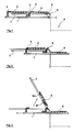
- FIG. 1 shows a bar 1 which can be moved in the direction of the arrow over approximately half its length.
- Two driver pins 2, 3 are fastened to the beam by means of screwing.
- a sheet metal table 8 there are two steel mats 4, 5.
- This table has elongated slots through which the driving pins 2 and 3 can move freely.
- an arm 7 is shown, which is attached to a rotatable shaft 6.
- slots are provided in the sheet metal table, so that the arms 7 can freely rotate from their illustrated rest position by approximately 180 ° in the clockwise direction to the stacking position 9.
- a lever arm 64 for example, on which a hydraulic motor 63 acts (see FIG.
- the stacking machine can be adapted to the new conditions in just a few minutes - adjusting the driving pins 2, 3 on the bar and entering the new data into the computer.
- the sheet table 8 is approximately at the level at which the mats come out of the tracks 60, 61 of the welding machine (see FIG. 6). Between the latter and the stacking machine, a set of driven rollers 62 is arranged, which convey the steel mats into the desired position on the table 8 next to the stacking position 9.
- the arms 7 In the last position shown (see FIG. 4) of the stacking machine, the arms 7 have rotated about 180 °. The steel mat 4 is still held on the arms 7 while the mat 5 is on the stack.
- the usual guide elements 40 are also indicated here, which prevent the mats from breaking out during the free fall and ensure an integrity stack. Such elements are advantageous but not absolutely necessary. After releasing the mat, the arms 7 move back into their starting position and the next two mats can be pushed onto the table 9.
- the hook 5 consists essentially of two hooks, one (reference numeral 50) at the level of outermost longitudinal rod of the mat 4, on which the arm 7 is fastened and the second (reference numeral 52) can be moved via an air pressure cylinder 51. Both hooks are slightly curved in the direction of the longitudinal bars to be clamped. In order not to impair the longitudinal displacement of the mats 4 out of the welding machine, the hooks 50, 52 are located just below the table level. When the shaft 6 rotates, the mat comes to rest on the arms and slides a few centimeters until it rests on the hook 50; then the air pressure cylinder 51 is pressurized and the hook 52 clamps the mat.
- the air pressure which ensures a firm hold of the mat on the arm without damaging the rods / welding points, is determined by simple tests. Since the air pressure cylinder can move the hook 52 over a greater distance, there is in principle the possibility of clamping mats with different rod spacings without adjusting the hook 50 and the air pressure cylinder 51. In order to prevent the hook from breaking out laterally, it can be advantageous for heavy mats to be attached to a trolley; the rollers are guided in a longitudinal rail attached to the arm 7.
- electromagnets can also be used. However, it must be taken into account here that these magnetize the mats, which is undesirable for many customers.
- the same reference numerals have been used as before, so that further explanations are unnecessary. It should also be noted here that the functional interaction of the parts is to be explained but their relative dimensions are incorrect.
- the machine has three bars 1 and three rotating arms 7 provided with clamping devices; As can be seen from the stack 9, the mats have the nominal width but only about 2/3 of the length for which the machine is designed. A part of the sheet table 8 has been omitted to show the rotating arm 6.
Abstract
Description
Die Erfindung betrifft eine Stapelmaschine für Baustahlmatten gemäss Oberbegriff des Anspruchs 1.The invention relates to a stacking machine for structural steel mats according to the preamble of
Stahlmatten bestehen aus rechtwinklig sich kreuzenden Bewehrungsstäben mit glatter, profilierter oder gerippter Oberfläche mit Durchmessern bis zu 16 mm, die an den Kreuzungspunkten durch Wiederstands-Punktschweissung miteinander verbunden sind. Die Matten werden heute auf fast allen Anwendungsgebieten des Hoch- und Tief-Stahlbetonbaues eingesetzt. Als industriell vorgefertigtes Bewehrungselement sind die Stahlmatten zum Massenprodukt geworden. Betonstahlmatten ersetzen überaus kostengünstig einen grossen Teil der beim Verlegen erforderlichen Handarbeit durch eine automatische Fertigung in der Fabrik. Insbesondere bei flächenartigen Bauteilen wie Decken, Sohlplatten, Betonfahrbahnen, wo nur in geringem Masse ein zusätzliches Schneiden und Biegen anfällt, wird der Kostenvorteil am grössten.Steel mats consist of reinforcing bars crossing at right angles with a smooth, profiled or ribbed surface with diameters of up to 16 mm, which are connected to each other at the crossing points by resistance spot welding. The mats are used today in almost all areas of high and low reinforced concrete construction. As an industrially prefabricated reinforcement element, the steel mesh has become a mass product. Reinforcing steel mats replace a large part of the manual work required for laying very cost-effectively with automatic production in the factory. The cost advantage is greatest, especially in the case of flat components such as ceilings, floor slabs, concrete roadways, where only a small amount of additional cutting and bending is required.
Ein weiteres vorteilhaftes Anwendungsgebiet ist die Fertigteilbauweise, bei der Stahlmatten in eine Verschalung eingebracht werden welche anschliessend mit Beton oder Gasbeton ausgegossen wird. Diese Stahlmatten haben festliegende Längen und Breiten die wesentlich kleiner sind als die der Matten welche in der Ortbetonbauweise eingesetzt werden; ausserdem haben die Bewehrungsstäbe nur einen Durchmesser von etwa 5 mm. Die Matten haben folglich einen relativ grossen Volumen/Gewicht Faktor. Aus Transportgründen werden die Matten derart gestapelt, dass die Querstäbe von zwei benach barten Matten jeweils nebeneinander zu liegen kommen. Jede zweite, aus der Widerstandsschweissmaschine kommende Matte wird folglich umgedreht, bevor sie auf den Stapel abgelegt wird. Zusätzlich kommt, dass üblicherweise eine Widerstandsschweissmaschine mit zwei Bahnen eingesetzt wird und die gefertigten Matten auf einem einzigen Stapel abgelegt werden.Another advantageous field of application is the prefabricated construction, in which steel mats are placed in a formwork which is then poured out with concrete or gas concrete. These steel mats have fixed lengths and widths that are significantly smaller than those of the mats used in in-situ concrete construction; in addition, the reinforcement bars have a diameter of only about 5 mm. The mats therefore have a relatively large volume / weight factor. For transport reasons, the mats are stacked in such a way that the cross bars of two adj beard mats come to lie next to each other. Every second mat coming out of the resistance welding machine is therefore turned over before it is placed on the stack. In addition, a resistance welding machine with two tracks is usually used and the mats produced are placed on a single stack.
Die vorliegende Erfindung hat sich als Aufgabe gestellt, eine Stapelmaschine zu schaffen, welche ein derartiges Stapeln erlaubt. Diese Aufgabe wird durch die in Anspruch 1 angegebene Erfindung gelöst. Vorteilhafte Ausgestaltungen der Erfindung sind in den abhängigen Ansprüchen angegeben.The object of the present invention is to create a stacking machine which permits such stacking. This object is achieved by the invention specified in
Die Erfindung wird anhand von Zeichnungen, welche eine Ausführmöglichkeit darstellen, näher erläutert. Es zeigen:
- - die Fig. 1 - 4 schematische Schnitte durch die Stapelmaschine in aufeinanderfolgenden Arbeitsstufen.
- - die Fig. 5, eine schematische Seitenansicht der Festklemmvorrichtung der Stahlmatte und
- - die Fig. 6, eine Draufsicht der Stapelmaschine.
- 1 - 4 are schematic sections through the stacking machine in successive work stages.
- - Fig. 5, a schematic side view of the clamping device of the steel mat and
- 6 is a top view of the stacking machine.
Auf Fig. 1 ist ein Balken 1 zu erkennen, der über etwa die Hälfte seiner Länge in Pfeilrichtung verschoben werden kann. An dem Balken sind zwei Mitnehmerstifte 2, 3 mittels Verschraubung befestigt. Auf einem Blechtisch 8 liegen zwei Stahlmatten 4, 5. Dieser Tisch besitzt längliche Schlitze, durch die sich die Mitnehmerstifte 2 und 3 frei bewegen können. Ausserdem ist ein Arm 7 dargestellt, welcher an einer drehbaren Welle 6 befestigt ist. Auch hier sind Schlitze in dem Blechtisch vorgesehen, so dass die Arme 7 sich aus ihrer dargestellten Ruhelage um etwa 180° in Uhrzeiger-Richtung, zur Stapelposition 9 hin, frei drehen können. Um die Arme 7 zu bewegen, kann bspw. ein Hebelarm 64, auf den ein Hydraulikmotor 63 wirkt (siehe Fig.6) an der Welle 6 befestigt werden; die Balken 1 werden vorteilhafterweise über Zahnstangen durch Elektromotoren 65 bewegt. Die verschiedenen Lagen der Balken 1 und der Dreharme 7 werden mittels Sensoren überwacht, welche an einen Rechner angeschlossen sind. Der Rechner steuert den Elektro- und den Hyraulik-Motor sowie die Festklemmvorrichtung, auf die näher anhand von Fig. 5 eingegangen wird. Bei Aenderung der Abmessungen oder der Stababstände der verschweissten Stahlmatten kann mittels weniger Handgriffe -Verstellen der Mitnehmerstifte 2, 3, auf den Balken sowie Eingabe der neuen Daten in den Rechner- in wenigen Minuten die Stapelmaschine den neuen Gegebenheiten angepasst werden. Es sei noch bemerkt, dass der Blechtisch 8 sich etwa auf der Höhe befindet auf der die Matten aus den Bahnen 60, 61 der Schweissmaschine (siehe Fig. 6) kommen. Zwischen letzteren und der Stapelmaschine ist ein Satz angetriebener Rollen 62 angeordnet, welche die Stahlmatten in die gewünschte Lage auf dem Tisch 8 befördern i.e. neben die Stapelposition 9.1 shows a
Auf Fig. 2 ist ein Balken 1 in ausgefahrener Lage zu erkennen. Die Mitnehmerstifte 3 haben die Matte 5 vom Tisch 8 geschoben und diese liegt nun frei auf den Balken 1. Die seitliche Bewegung der Balken 1 hat über die Mitnehmerstifte 2 die Matte 4 derart verschoben, dass diese nun die frühere Lage der Matte 5 einnimmt.2 shows a
In der auf Fig. 3 dargestellten Lage, haben die Arme 7 sich um etwa 75° gedreht, wobei die Matte 4 durch die Festklemmvorrichtung 50, 51 auf den Armen festgehalten wird. Die Balken 1 können nunmehr in ihre Ausgangslage zurückgefahren werden und die Matte 5 fällt frei auf die Stapelposition 9.In the position shown in FIG. 3, the
In der letzten dargestellten Lage (siehe Fig.4) der Stapelmaschine haben die Arme 7 sich um etwa 180° gedreht. Die Stahlmatte 4 wird noch an den Armen 7 festgehalten, während die Matte 5 auf dem Stapel liegt. Zusätzlich sind hier noch die üblichen Führungselemente 40 angedeutet welche ein Ausbrechen der Matten während des freien Falles vermeiden und einen tadellosen Stapel sicherstellen. Derartige Elemente sind von Vorteil aber nicht unbedingt erforderlich. Nach dem Lösen der Matte fahren die Arme 7 in ihre Ausgangslage zurück und die zwei nächsten Matten können auf den Tisch 9 geschoben werden.In the last position shown (see FIG. 4) of the stacking machine, the
Die auf Fig. 5 dargestellte Festklemmvorrichtung besteht im wesentlichen aus zwei Haken, wobei der eine (Bezugszeichen 50) in Höhe des äussersten Längsstabes der Matte 4, an dem Arm 7 befestigt ist und der zweite (Bezugszeichen 52) über einen Luftdruckzylinder 51 bewegt werden kann. Beide Haken sind leicht in Richtung der zu klemmenden Längsstäbe hin gekrümmt. Um die Längs-Verschiebung der Matten 4 aus der Schweissmaschine heraus nicht zu beeinträchtigen, liegen die Haken 50, 52 knapp unter der Tischebene. Bei der Drehbewegung der Welle 6 kommt die Matte auf die Arme zu liegen und gleitet einige Zentimeter bis sie an dem Haken 50 anliegt; dann wird der Luftdruckzylinder 51 unter Druck gesetzt und der Haken 52 klemmt die Matte fest. Der Luftdruck, welcher einen festen Halt der Matte auf dem Arm sicherstellt ohne die Stäbe/Schweiss-Stellen zu beschädigen wird durch einfache Versuche bestimmt. Da der Luftdruckzylinder den Haken 52 über eine grössere Distanz bewegen kann, besteht im Prinzip die Möglichkeit, Matten mit verschiedenen Stababständen festzuklemmen ohne den Haken 50 und den Luftdruckzylinder 51 zu verstellen. Um ein seitliches Ausbrechen des Hakens zu vermeiden kann es bei schweren Matten von Vorteil sein, diesen an einem Rollwagen zu befestigen; die Rollen werden in einer am Arm 7 befestigten Längsschiene geführt.5 consists essentially of two hooks, one (reference numeral 50) at the level of outermost longitudinal rod of the
Neben einer mechanischen Festklemmvorrichtung, wobei die anhand der Fig. 5 beschriebene Ausführungsform sich besonders gut bewährt hat, kann auch auf Elektromagnete zurückgegriffen werden. Hier muss aber bedacht werden, dass diese die Matten magnetisieren, was bei vielen Kunden unerwünscht ist.In addition to a mechanical clamping device, the embodiment described with reference to FIG. 5 having proven particularly useful, electromagnets can also be used. However, it must be taken into account here that these magnetize the mats, which is undesirable for many customers.
Bei der auf Fig.6 gezeigten Draufsicht der Stapelmaschine -ohne Matten- wurden dieselben Bezugszeichen wie bisher verwendet, so dass weitere Erklärungen sich erübrigen. Bemerkt sei auch hier, dass das funktionelle Zusammenwirken der Teile erläutert werden soll aber deren relative Abmessungen nicht stimmen. In der dargestellten Ausführung besitzt die Maschine drei Balken 1 und drei, mit Festklemmvorrichtungen versehene Dreharme 7; wie aus dem Stapel9 ersichtlich, haben die Matten zwar die nominale Breite aber nur etwa 2/3 der Länge für die die Maschine ausgelegt ist. Ein Teil des Blechtisches 8 wurde weggelassen, um den Dreharm 6 zu zeigen.In the plan view of the stacking machine — without mats — shown in FIG. 6, the same reference numerals have been used as before, so that further explanations are unnecessary. It should also be noted here that the functional interaction of the parts is to be explained but their relative dimensions are incorrect. In the embodiment shown, the machine has three
Claims (6)
Applications Claiming Priority (2)
| Application Number | Priority Date | Filing Date | Title |
|---|---|---|---|
| LU87174A LU87174A1 (en) | 1988-03-18 | 1988-03-18 | STACKING MACHINE FOR MOLDING MATS |
| LU87174 | 1988-03-18 |
Publications (1)
| Publication Number | Publication Date |
|---|---|
| EP0333631A1 true EP0333631A1 (en) | 1989-09-20 |
Family
ID=19731033
Family Applications (1)
| Application Number | Title | Priority Date | Filing Date |
|---|---|---|---|
| EP89630053A Withdrawn EP0333631A1 (en) | 1988-03-18 | 1989-03-17 | Stacking machine for construction steel mats |
Country Status (2)
| Country | Link |
|---|---|
| EP (1) | EP0333631A1 (en) |
| LU (1) | LU87174A1 (en) |
Cited By (2)
| Publication number | Priority date | Publication date | Assignee | Title |
|---|---|---|---|---|
| WO2004007109A1 (en) * | 2002-07-15 | 2004-01-22 | Beta Systems Srl | Device for the automatic formation of packs of panels of electro-welded mesh and relative method |
| KR20200131986A (en) * | 2019-05-15 | 2020-11-25 | 유한회사 상관철망 | Wire mesh loading device |
Citations (3)
| Publication number | Priority date | Publication date | Assignee | Title |
|---|---|---|---|---|
| AT239037B (en) * | 1963-09-02 | 1965-03-10 | Evg Entwicklung Verwert Ges | Device for turning and stacking welded mesh mats emerging from automatic welding machines |
| AT366937B (en) * | 1978-11-08 | 1982-05-25 | Evg Entwicklung Verwert Ges | DEVICE FOR THE MACHINE STACKING OF GRIDS UNDER ALTERNATIVE TURNING THEREOF |
| DE3237255A1 (en) * | 1982-10-08 | 1984-04-12 | Reinking Maschinenbau GmbH, 4993 Rahden | Process for the mechanical stacking of grid mats emerging from a grid welding machine, and apparatus for implementing the process |
-
1988
- 1988-03-18 LU LU87174A patent/LU87174A1/en unknown
-
1989
- 1989-03-17 EP EP89630053A patent/EP0333631A1/en not_active Withdrawn
Patent Citations (3)
| Publication number | Priority date | Publication date | Assignee | Title |
|---|---|---|---|---|
| AT239037B (en) * | 1963-09-02 | 1965-03-10 | Evg Entwicklung Verwert Ges | Device for turning and stacking welded mesh mats emerging from automatic welding machines |
| AT366937B (en) * | 1978-11-08 | 1982-05-25 | Evg Entwicklung Verwert Ges | DEVICE FOR THE MACHINE STACKING OF GRIDS UNDER ALTERNATIVE TURNING THEREOF |
| DE3237255A1 (en) * | 1982-10-08 | 1984-04-12 | Reinking Maschinenbau GmbH, 4993 Rahden | Process for the mechanical stacking of grid mats emerging from a grid welding machine, and apparatus for implementing the process |
Cited By (3)
| Publication number | Priority date | Publication date | Assignee | Title |
|---|---|---|---|---|
| WO2004007109A1 (en) * | 2002-07-15 | 2004-01-22 | Beta Systems Srl | Device for the automatic formation of packs of panels of electro-welded mesh and relative method |
| CN1297361C (en) * | 2002-07-15 | 2007-01-31 | 倍塔赛斯特姆有限公司 | Device for the automatic formation of packs of panels of electro-welded mesh and relative method |
| KR20200131986A (en) * | 2019-05-15 | 2020-11-25 | 유한회사 상관철망 | Wire mesh loading device |
Also Published As
| Publication number | Publication date |
|---|---|
| LU87174A1 (en) | 1989-10-26 |
Similar Documents
| Publication | Publication Date | Title |
|---|---|---|
| DE4396373B4 (en) | Binding device, magazine, apparatus and method for this purpose, and the binding device exhibiting reinforced concrete structure | |
| DE2744235C2 (en) | ||
| DE2159714B2 (en) | Method and device for separating aerated concrete elements | |
| DE2952026A1 (en) | BENDING MACHINE FOR THE SIMULTANEOUS BENDING OF CONCRETE STEEL WIRE WITH STRUCTURAL MAT | |
| DE2802621A1 (en) | METAL SHEET MOLDING MACHINE | |
| DE2627845C2 (en) | Method and device for setting sleepers on the ballast bed of a track | |
| DE3331341C2 (en) | Device for the transverse transport of a profile rod for profile rod processing lines with longitudinal transport roller table | |
| DE2245215B2 (en) | THREADLADDER | |
| DE2911735A1 (en) | BOW FEEDER | |
| EP0333631A1 (en) | Stacking machine for construction steel mats | |
| DE2947581A1 (en) | SHEET CUTTER | |
| DE3941291A1 (en) | BENDING SYSTEM FOR STEEL ROD | |
| EP0414061B1 (en) | Device for drawing a metal rod out of a rod bundle | |
| DD239735A5 (en) | COMPACTING DEVICE FOR THE AUTOMATIC LOADING OF LOADS | |
| DE2446768C3 (en) | Device for vibrating dowels in concrete road surfaces | |
| DE2627058A1 (en) | STOP DEVICE FOR POSITIONING A PLATE ON A MACHINE TOOL | |
| CH687008A5 (en) | Bending device for long wire ends of concrete plate reinforcement grid | |
| DE3220805C2 (en) | Paper sheet gathering machine | |
| DE3808754C2 (en) | Process for the introduction of press piles and sheet piles | |
| DE497749C (en) | Device for attaching tie hooks in building panels made of straw | |
| EP0094929A1 (en) | Method and cutting apparatus for subdividing into trellis mats a trellis web consisting of longitudinal wires and rectangularly traversing cross wires | |
| AT225403B (en) | Format saw | |
| DE7736974U1 (en) | Device for clamping and aligning a layer of concrete blocks with composite elements to form a laying unit | |
| EP0607914A1 (en) | Device for feeding workpieces in an automatic woodworking machine tool | |
| DE3924414A1 (en) | Storage and feed mechanism for rod material on notching machine - has several stacked inclined surfaces with adjustable side walls forming magazine |
Legal Events
| Date | Code | Title | Description |
|---|---|---|---|
| PUAI | Public reference made under article 153(3) epc to a published international application that has entered the european phase |
Free format text: ORIGINAL CODE: 0009012 |
|
| AK | Designated contracting states |
Kind code of ref document: A1 Designated state(s): AT BE CH DE FR IT LI NL |
|
| STAA | Information on the status of an ep patent application or granted ep patent |
Free format text: STATUS: THE APPLICATION IS DEEMED TO BE WITHDRAWN |
|
| 18D | Application deemed to be withdrawn |
Effective date: 19900321 |