EP0333591A2 - Process for formation of resist patterns - Google Patents
Process for formation of resist patterns Download PDFInfo
- Publication number
- EP0333591A2 EP0333591A2 EP89400743A EP89400743A EP0333591A2 EP 0333591 A2 EP0333591 A2 EP 0333591A2 EP 89400743 A EP89400743 A EP 89400743A EP 89400743 A EP89400743 A EP 89400743A EP 0333591 A2 EP0333591 A2 EP 0333591A2
- Authority
- EP
- European Patent Office
- Prior art keywords
- resist
- process according
- resist layer
- layer
- etching
- Prior art date
- Legal status (The legal status is an assumption and is not a legal conclusion. Google has not performed a legal analysis and makes no representation as to the accuracy of the status listed.)
- Granted
Links
Images


Classifications
-
- G—PHYSICS
- G03—PHOTOGRAPHY; CINEMATOGRAPHY; ANALOGOUS TECHNIQUES USING WAVES OTHER THAN OPTICAL WAVES; ELECTROGRAPHY; HOLOGRAPHY
- G03F—PHOTOMECHANICAL PRODUCTION OF TEXTURED OR PATTERNED SURFACES, e.g. FOR PRINTING, FOR PROCESSING OF SEMICONDUCTOR DEVICES; MATERIALS THEREFOR; ORIGINALS THEREFOR; APPARATUS SPECIALLY ADAPTED THEREFOR
- G03F7/00—Photomechanical, e.g. photolithographic, production of textured or patterned surfaces, e.g. printing surfaces; Materials therefor, e.g. comprising photoresists; Apparatus specially adapted therefor
- G03F7/004—Photosensitive materials
- G03F7/075—Silicon-containing compounds
- G03F7/0757—Macromolecular compounds containing Si-O, Si-C or Si-N bonds
- G03F7/0758—Macromolecular compounds containing Si-O, Si-C or Si-N bonds with silicon- containing groups in the side chains
-
- G—PHYSICS
- G03—PHOTOGRAPHY; CINEMATOGRAPHY; ANALOGOUS TECHNIQUES USING WAVES OTHER THAN OPTICAL WAVES; ELECTROGRAPHY; HOLOGRAPHY
- G03F—PHOTOMECHANICAL PRODUCTION OF TEXTURED OR PATTERNED SURFACES, e.g. FOR PRINTING, FOR PROCESSING OF SEMICONDUCTOR DEVICES; MATERIALS THEREFOR; ORIGINALS THEREFOR; APPARATUS SPECIALLY ADAPTED THEREFOR
- G03F7/00—Photomechanical, e.g. photolithographic, production of textured or patterned surfaces, e.g. printing surfaces; Materials therefor, e.g. comprising photoresists; Apparatus specially adapted therefor
- G03F7/26—Processing photosensitive materials; Apparatus therefor
- G03F7/36—Imagewise removal not covered by groups G03F7/30 - G03F7/34, e.g. using gas streams, using plasma
Definitions
- the present invention relates to a process for the formation of resist patterns, particularly negative resist patterns.
- the pattern formation process of the present invention can be effectively used in both a single layer resist process and a two layer resist process currently used to obtain resist patterns having a high resolution and aspect ratio on a substrate having topographic features.
- the resulting resist patterns can be advantageously used in the production of semiconductor devices such as large-scale integrated (LSI) circuits, very-large-scale integrated (VLSI) circuits, and bubble memory devices, and the like.
- a thin layer formation technology and lithography are widely utilized in the production of LSI, VLSI, and the like, for example.
- An important process in this technology is a resist process used in the field of fine fabrication.
- the resist process is classified into a single layer resist process and a multilayer resist process, such as a two layer or three layer resist process.
- a plurality of negative-working or positive-working resist materials are used depending upon the desired results and other factors.
- the single layer resist process using a negative-working resist material is conducted as follows: A solution of the selected resist material is coated on a substrate and then dried to form a resist layer. The resist layer is patterned by exposure to light or radiation to which the resist material is sensitive, for example, ultraviolet radiation. As a result of this exposure, the resist material in an exposed area of the resist layer is insolubilized in a developing solution such as organic solvents. The mechanism of insolubilization is based on, for example, cross-linking of the resist material. The exposed resist layer is developed with the developing solution to remove the unexposed resist material from the resist layer, and a negative resist pattern is thus formed on the substrate.
- This process has a drawback, however, in that a high quality resist pattern cannot be obtained, since the substrate is swollen as a result of contact thereof with the solvent used as the developer in the wet development step.
- the inventor created an improved resist process as disclosed in Japanese Unexamined Patent Publication (Kokai) No. 63-15240, in which the resist process or patterning process comprises coating a resist material having a polymer having a double bond or triple bond in a backbone chain thereof, as a main component, on a substrate to form a layer of the resist material, exposing a selected area of the layer to ultraviolet radiation, X-rays or electron beams, and developing the exposed layer with the down flow etching method using an oxygen-containing gas.
- the polymer includes, for example, 1,4-polybutadiene, 1,4-polybutadiyne or derivatives thereof, and contains one or more benzene rings and chlorine atoms in a polymeric structure thereof.
- the oxygen-containing gas used in the development step is, for example, a mixture of oxygen and carbon tetrafluoride. According to the process of Japanese Kokai 63-15240, since specific polymers containing unsaturated bonds as well as benzene rings and chlorine atoms are used as the resist material and the exposed resist material is developed with a dry process, high quality negative resist patterns can be obtained.
- the substrate used in the production of the semiconductor devices and the like may comprise any material such as a semiconductor, for example, silicon (Si).
- the substrate may have any layer such as an insulating layer, for example, SiO2 layer or a polysilicon layer on a surface thereof, and further, may contain topographic features, i.e., concaves and convexes, on a surface thereof.
- the topographic features are produced, for example, when an electrically insulating layer is coated over the surface of the circuit pattern-bearing substrate, and the topographic features have a height of about 1 to 2 ⁇ m.
- the substrate to be processed has topographic features
- the topographic features adversely affect the resulting resist patterns. Namely, due to a disordered reflection of exposure light or radiation such as electron beams at the concaves and convexes in the resist patterns, the formation of fine resist patterns at a high accuracy is impossible.
- a multilayer resist process especially a two layer resist process has been used to obtain fine resist patterns of a submicron order on the topographic features-bearing substrate.
- the two layer resist process generally comprises coating an organic resist material such as phenol-novolac resin or cresol-novolac resin on the substrate to level the topographic features thereof.
- the resulting resist layer (hereinafter “lower resist layer”) is relatively thick and has a thickness of about 2 to 3 ⁇ m, for example.
- a polymeric resist material having a high resistance to dry etching such as chloromethylated polydiphenyl siloxane of the structure formula: wherein m represents a polymerization degree ("SNR" commercially available from Tosoh Corporation) or a copolymer of trimethylsilylstyrene and chloromethyl styrene of the structural formula: is coated on the lower resist layer.
- SNR polymerization degree
- the resulting layer (hereinafter "upper resist layer”) is remarkably thinner than the lower resist layer and generally has a thickness of about 0.2 to 0.5 ⁇ m.
- silicon-containing polymers are suitable as the upper resist material is that these polymers also can form an SiO x layer having a high resistance to dry etching during the subsequent O2-RIE (reactive ion etching) generally used to transfer a pattern of the upper resist layer to the lower resist layer.
- O2-RIE reactive ion etching
- a pattern formation is conducted as follows:
- the upper resist layer is patterned by exposure to light or radiation, for example, by applying a projection exposure or contact exposure, through a mask, to the resist layer.
- an exposed area of the layer is insolubilized in a developing solution.
- the exposed upper resist layer is then developed with the developing solution to remove an unexposed area thereof, and a pattern of the upper resist layer is thus formed.
- the underlying lower resist layer is dry etched with, for example, O2-RIE, to transfer the pattern of the upper resist layer to the lower resist layer, and a desired negative resist pattern is finally obtained.
- Example 1 of Japanese Kokai 58-165321 discloses spin-coating polyimide on a silicon wafer to form a lower resist layer having a thickness of 1 ⁇ m.
- the lower resist layer is then coated with a mixture (5:1) of polyglycidyl methacrylate and dimethyldiphenylsilane to form an upper resist layer having a thickness of 0.2 ⁇ m.
- the resulting resist structure is pattern-wise exposed to electron beams, and then developed using a plasma of oxygen gas and Freon R gas. The unexposed area of the upper resist layer is thus removed.
- the resist structure is dry etched.
- a retention rate of the resist i.e., ratio (%) of the thickness of the resist after development to that of the resist before development in the same area of the resist layer where the resist should be retained, can be improved.
- the prior art two layer resist process has a disadvantage in that a retention rate of the resist in the resulting resist patterns is not satisfactory because physical actions such as ion bombardment during the O2-RIE adversely affect the improvement of such retention rate.
- the silicon-containing resist or polymer is prepared by introducing a silicon atom into the organic resist or polymer, an amount of the silicon in the resulting upper resist patterns is limited and, in practice, is not high enough to ensure a satisfactory resistance to the O2-RIE of the upper resist layer during etching of the lower resist layer. It is, therefore, desired to provide an improved process for the resist pattern formation which ensures a formation of fine resist patterns of a submicron order at a high resolution and retention rate of the resist. It is also desired to confer a high resistance to dry etching such as the O2-RIE to the resulting resist patterns.
- a process for the formation of resist patterns comprising preparing a resist material by mixing a silicon-containing polymer with an addition agent which can bond to the polymer upon an addition reaction when a mixture of the polymer and the addition agent is exposed to radiation, coating the resist material on a substrate to form a resist layer, exposing the resist layer to a pattern of the radiation, and dry developing the exposed resist layer with an oxygen-containing etching gas in the absence of plasma of the gas in an etching chamber positioned apart from a plasma generation chamber to form the resist patterns on the substrate.
- the silicon-containing polymer used as a main resist material in the present invention preferably contains at least one unsaturated bond such as a double bond and triple bond in a backbone chain of the recurring unit thereof, although the polymer containing only single bonds is also available.
- the addition agent used in combination with the silicon-containing polymer is preferably an olefin, azide, imide or derivatives thereof, and further preferably, contains at least one substituent selected from the group consisting of aromatic groups such as benzene ring and halogen atoms such as chlorine.
- Developing of the exposed resist layer is preferably carried out with dry etching by using an oxygen-containing etching gas as the active species in the absence of plasma of the gas in an etching chamber positioned apart from a plasma generation chamber.
- This development process is generally referred to as a down flow etching process and will be further described hereinafter.
- a process for the formation of resist patterns comprising forming a two-layered resist structure on a substrate having topographic features on a surface thereof by coating on the surface, in sequence, a lower resist layer having a layer thickness enough to level the topographic features from an organic resist and an upper resist layer from a resist material prepared by mixing a silicon-containing polymer with an addition agent which can bond to the polymer upon an addition reaction when a mixture of the polymer and the addition agent is exposed to radiation, exposing the resist structure to a pattern of the radiation, dry developing the exposed resist structure with an oxygen-containing etching gas in the absence of plasma of the gas in an etching chamber positioned apart from a plasma generation chamber to form patterns of the upper resist layer on the lower resist layer, and further etching the lower resist layer, through the patterns of the upper resist layer as a mask, using a dry plasma etching method to etch an unmasked lower resist layer so that the patterns of the upper resist layer are transferred to the lower resist layer, to
- a mixture of the silicon-containing polymer and the addition agent is used as the resist material.
- the silicon-containing polymer used may be optionally selected from a variety of well-known polymers which satisfy the requirements of the present process.
- the silicon-containing polymer preferably contains at least one unsaturated bond such as a double or triple bond.
- Typical examples of such useful silicon-containing polymers includes silylated polyacetylenes such as poly(1-methyl, 2-trimethylsilyl) acetylene, poly[1,2-bis(trimethylsilyl)]acetylene or the like and other silicon-containing polymers such as polymethylsilylmethacrylate, poly trimethylsilylmethacrylate, poly(3-pentamethyldisiloxane)methacrylate and the like, although the present invention is not restricted to these polymers.
- silylated polyacetylenes such as poly(1-methyl, 2-trimethylsilyl) acetylene, poly[1,2-bis(trimethylsilyl)]acetylene or the like
- other silicon-containing polymers such as polymethylsilylmethacrylate, poly trimethylsilylmethacrylate, poly(3-pentamethyldisiloxane)methacrylate and the like, although the present invention is not restricted to these polymers.
- single bond-containing and triple bond-containing polymers are also available.
- An example of the single bond-containing polymers is and an example of the triple bond-containing polymers is wherein n represents a polymerization degree.
- the addition agent used in admixture with the silicon-containing polymer, as previously described, is preferably an olefin, azide, imide or derivatives thereof.
- the addition agent contains at least one substituent such as aromatic groups, for example, benzene ring, or halogen atoms, for example, chlorine or bromine atoms.
- Typical examples of useful addition agent include, for example, cinnamoyl chloride, diphenylacetylene, 2,3-diphenylbutadiene, benzyl cinnamate, 2-cinnamoylthiophene, 2,2-dimethoxy-2-phenylacetophenone, 4-azidebenzalcyclohexane, 1,4-diphenylpolybutadiene, 2,6-dichloroquinonechloroimide, 2,6-dibromoquinonechloroimide or chloranil.
- Other compounds may be used as the addition agent, insofar as they can bond to the polymer upon the addition reaction as a result of exposure to suitable radiation.
- the silicon-containing polymer and addition agent may be blended in a wide range of mixing ratios, depending upon factors such as desired results and the like.
- the resist material can be coated from a solution thereof onto a surface of the substrate such as a silicon substrate or wafer. Spin coating is preferably used. In addition, if appropriate, vacuum deposition or other coating methods may be used to form the resist layer.
- the above-described resist layer is used as an upper resist layer and is coated after the underlying resist layer "lower resist layer" has been coated on the substrate.
- the resist material for the lower resist layer is optional and can be selected from the well-known resist materials such as phenol resins, polyimide resins, polystyrene resins, epoxy resins, novolac resins, and the like.
- the single resist layer or upper resist layer is then exposed to a desired pattern of light or radiation which can cause an addition reaction of the polymer and addition agent in the layer.
- Useful exposure sources include light such as visible light as well as radiation such as ultraviolet radiation, deep ultraviolet radiation, X-rays, electron beams and ion beams.
- the resist layer is developed with the down flow etching method.
- the resist layer is dry developed with an oxygen-containing etching gas as an active species in the absence of plasma of said gas in an etching chamber positioned apart from a plasma generation chamber.
- the etching gas is downwardly introduced into said etching chamber, while the plasma of gas is retained in the plasma generation chamber.
- the etching gas is preferably produced from a mixture of oxygen (O2) gas and carbon tetrafluoride (CF4) gas.
- O2 oxygen
- CF4 carbon tetrafluoride
- a mixed resist of the silicon-containing polymer for example, polyacetylene with a silyl group
- the addition agent for example, olefin
- R1 , R2 , R3 , R4 , R5 and R6 may be the same or different and each represents a hydrogen atom or a substituted or unsubstituted alkyl or aryl group, and n represents a polymerization degree.
- the resist layer is developed with the down flow etching method using an oxygen-containing gas (for example, a mixed gas of O2/CF4). Etching of the resist is predominantly made in an exposed area of the resist layer, and as a result, a negative resist pattern corresponding to the pattern of the exposure light or radiation is formed.
- an oxygen-containing gas for example, a mixed gas of O2/CF4
- the negative resist pattern thus obtained can be used as a mask in the production of semiconductor devices or other devices. Further, if the resist layer is an upper resist layer of the two layer resist structure, the negative resist pattern can be used as a mask for etching in transferring a pattern of the upper resist layer to the lower resist layer. Etching in such instances can be advantageously carried out by using a dry plasma etching method such as O2-RIE or ECR (electron cyclotron resonance) etching, although development of the lower resist layer according to the present invention is not restricted to these two methods.
- a dry plasma etching method such as O2-RIE or ECR (electron cyclotron resonance) etching
- the inventor further found that undesirable shifting of the resulting patterns in the two layer resist process can be effectively prevented if a mixture of high silicon polymer such as polyacetylene having an unsaturated bond in a backbone chain of the recurring unit thereof and at least two silicon atoms on a side chain thereof and addition agent such as ultraviolet absorbing agent is used as the resist material.
- Useful high silicon polymers include, for example, poly 4,4,6,6-tetramethyl-4,6-disila-2-heptyne (PTMDSH) and poly 4,4,7,7-tetramethyl-4,7-disila-2-octyne (PTMDSO): wherein n represents a polymerization degree.
- polymers containing only one silicon atom on a side chain tereof such as poly 1-(trimethylsilyl)propyne (PTMSP) of the following structural formula: wherein n represents a polymerization degree, can provide good results.
- PTMSP poly 1-(trimethylsilyl)propyne
- the above two layer resist process comprises the steps of: forming a lower resist layer of the organic resist on a substrate to be processed to level topographic features of the substrate; further forming an upper resist layer of the above-described high silicon polymer and ultraviolet absorbing agent over the lower resist layer; patterning the upper resist layer by exposure to ultraviolet radiation; heating the substrate under a reduced pressure to remove the unreacted ultraviolet absorbing agent from the upper resist layer; developing the exposed upper resist layer with the down flow etching method using a O2/CF4 gas to obtain a pattern of the upper resist layer; and, etching the lower resist layer, through a mask of the patterned upper resist layer, with anisotropic plasma etching.
- the exposed silicon-containing resist layer (and the upper resist layer in the two layer resist process) is dry developed without using a developer solution, it is possible to easily produce fine resist patterns of a submicron order. As appreciated from the above description, this is because swelling of the resist layer is avoided due to the absence of the developer solution. Further, since the dry development is carried out in accordance with the down flow etching process, namely, development is not conducted in an atmosphere of O2 plasma as in a conventional prior art dry development process, but is based on chemical reactions free from ion bombardment, the retention rate of the resist can be remarkably improved.
- the silicon-containing polymer which silicon content can be easily adjusted to a high level
- the resist material since the silicon-containing polymer, which silicon content can be easily adjusted to a high level, is used as the resist material, if the high silicon polymer is used as the upper resist layer in the two layer resist process, a satisfactorily increased resistance to O2-RIE can be attained during RIE etching of the lower resist layer.
- pattern shifting of the resist during RIE etching of the lower resist layer is eliminated or reduced to regligible, proportions, the production yield of the devices, and the characteristics thereof, are improved.
- a mixture (2:1) of poly(1-methyl, 2-trimethylsilyl acetylene as the silicon-containing polymer and cinnamoyl chloride as the addition agent was dissolved in xylene to prepare a ca. 1% by weight resist solution, and the resist solution was spin-coated on the substrate.
- the substrate used herein was a silicon substrate or wafer having cleaned surfaces. After drying, as illustrated in Fig. 1A, a resist layer 2 having a layer thickness of about 400 nm was formed on an upper surface of the substrate 1.
- the resist layer 2 was patterning exposed through a mask (not shown) to radiation from an Xe-Hg lamp for about 30 seconds.
- the contact exposure method was used and an illuminance on a surface of the wafer during exposure was about 5 mW/cm2.
- An exposed area 12 of the resist layer 2 showed an increased resistance to dry etching in the next development step.
- Development of the exposed resist layer was made in a developing apparatus of Fig. 3.
- the wafer 10 was placed in an etching chamber 15 of the developing apparatus 4 and carried with a wafer holder 9.
- a mixed gas of O2/CF4 as a reaction gas was introduced from a gas inlet 6 into a plasma generator 14 of the apparatus 4, and exhausted from a gas outlet 7 of the same apparatus 4.
- a microwave (not shown) from a magnetron 5 was guided into the plasma generation chamber 14, and applied to the downwardly flowing reaction gas to generate plasma of the reaction gas.
- the plasma itself was stopped with a shield plate 8 for the microwave, but radicals of the atoms constituting the reaction gas (neutral active species) generated together with the gas plasma entered the etching chamber through openings of the shield plate 8.
- the exposed resist layer (not shown) of the wafer 10 was thus developed with the downwardly flowing plasma-free etching gas.
- the conditions used in this development step were as follows: Flow rate of O2: 1000 SCCM, Flow rate of CF4: 500 SCCM, Pressure: 6 Torr, Power of microwave: 750 W.
- a negative pattern 12 of the resist layer was formed on the substrate (see Fig. 1C). It was observed that the resist pattern had a retention rate of the resist of about 90% and a resolution of about 0.5 ⁇ m 1/s (line & space).
- Figure 2A illustrates a cross-section of the two layer resist structure used in this example.
- the substrate 1 was a silicon wafer and, as illustrated, contained topographic features.
- the resist structure was prepared as follows.
- the novolac resist: OFPR-800, products of Tokyo Oka Laboratories Limited was spin-coated on an upper surface of the silicon wafer 1 to level the unevennesses of the wafer surface, and a lower resist layer 3 having a layer thickness of about 2 ⁇ m was thus formed on the silicon wafer 1. Thereafter, the same resist material as used in Example 1 was spin-coated on the lower resist layer 3 in accordance with the procedure of Example 1, and an upper resist layer 2 having a thickness of about 400 nm was produced.
- the upper resist layer 2 was patterning exposed as in Example 1 and as shown in Fig. 2B.
- An exposed area 12 of the resist layer 2 on the lower resist layer 3 showed an increased resistance to dry etching.
- the exposed upper resist layer 2 was then developed as in the development step of Example 1, and as shown in Fig. 2C, a negative pattern 12 of the resist layer was formed as a result of this development.
- the underlying lower resist layer 3 was dry etched with O2-RIE to transfer the pattern 12 to the layer 3 (see Fig. 2D).
- the conditions for this reactive dry etching using O2 gas were as follows: Flow rate of O2: 100 SCCM, Pressure: 0.03 Torr, Output: 500 W.
- the unmasked area of the lower resist layer 13 was selectively etched as a result of this etching, and as shown in Fig. 2E, a negative pattern of the resist 12 plus 13 was eventually formed on the topographic features-bearing substrate 1. It was observed that the resist pattern had a thickness of 2 ⁇ m and a resolution of 0.5 ⁇ m 1/s.
- Example 2 The procedure of Example 1 was repeated, except that polytrimethylsilylmethacrylate was used as the silicon-containing polymer and diphenylacetylene as the addition agent, respectively, and finally, a negative pattern of the resist layer was formed on the substrate. It was observed that the resist pattern had a retention rate of the resist of 60%, a resolution of 1 ⁇ m, and a sensitivity of 300 mJ.
- Example 1 The procedure of Example 1 was repeated, except that poly[1,2-bis(trimethylsilyl)]acetylene] was used in place of poly(1-methyl, 2-trimethylsilyl)acetylene, and a negative resist pattern having a retention rate of the resist of 90%, a resolution of 0.5 ⁇ m, and a sensitivity of 120 mJ was formed.
- Example 2 The procedure of Example 1 was repeated, except that poly(3-pentamethyldicyclohexane methacrylate was used in place of poly(1-methyl, 2-trimethylsilyl)acetylene, and a negative resist pattern having a retention rate of the resist of 70%, a resolution of 0.8 ⁇ m, and a sensitivity of 200 mJ was formed.
- a mixture (3:2) of poly(1-methyl, 2-trimethylsilyl)acetylene as the silicon-containing polymer and 2,3-diphenylbutadiene as the addition agent was dissolved in xylene to prepare a ca. 1% by weight resist solution.
- the formation of a resist layer (thickness of about 300 nm), and the exposure and development were performed as in Example 1, and as a result, a negative resist pattern having a retention rate of the resist of 80%, a resolution of 0.5 ⁇ m, and a sensitivity of 150 mJ was obtained.
- Example 6 The same procedure as in Example 6 was repeated, except that diphenylacetylene was used in place of 2,3-diphenylbutadiene, and a negative resist pattern having a retention rate of the resist of 95%, a resolution of 2 ⁇ m, and a sensitivity of 230 mJ was obtained.
- Example 6 The same procedure as in Example 6 was repeated, except that benzyl cinnamate was used in place of 2,3-diphenylbutadiene, and a negative resist pattern having a retention rate of the resist of 75%, a resolution of 0.6 ⁇ m, and a sensitivity of 120 mJ was obtained.
- Example 6 The same procedure as in Example 6 was repeated, except that 2-cinnamoylthiophene was used in place of 2,3-diphenylbutadiene, and a negative resist pattern having a retention rate of the resist of 85%, a resolution of 0.5 ⁇ m, and a sensitivity of 200 mJ was obtained.
- Example 6 The same procedure as in Example 6 was repeated, except that 2,2-dimethoxy-2-phenylacetophenone was used in place of 2,3-diphenylbutadiene, and a negative resist pattern having a retention rate of the resist of 60%, a resolution of 1.0 ⁇ m, and a sensitivity of 100 mJ was obtained.
- Example 6 The same procedure as in Example 6 was repeated, except that 4-azidobenzalcyclohexanone was used in place of 2,3-diphenylbutadiene, and a negative resist pattern having a retention rate of the resist of 75%, a resolution of 0.7 ⁇ m, and a sensitivity of 70 mJ was obtained.
- Example 6 The same procedure as in Example 6 was repeated, except that 1,4-diphenylpolybutadiene was used in place of 2,3-diphenylbutadiene, and a negative resist pattern having a retention rate of the resist of 80%, a resolution of 1.5 ⁇ m, and a sensitivity of 200 mJ was obtained.
- a mixture (3:2) of poly trimethylsilyl methacrylate and diphenylacetylene was dissolved in methyl cellosolve acetate to prepare a ca. 8% by weight resist solution.
- a silicon wafer was spin-coated with this solution, followed by drying to form a resist layer (thickness of about 300 nm).
- the resist layer was subjected to contact exposure for about 30 seconds by using an Xe-Hg lamp and then baked at about 70°C in vacuum. Development of the exposed resist layer was then carried out under conditions of an O2 flow rate of 1500 SCCM, a CF4 flow rate of 300 SCCM, 3 Torr and 750 W on the down flow developing apparatus as in Example 1.
- a negative resist pattern having a retention rate of the resist of 50%, a resolution of 1.5 ⁇ m, and a sensitivity of 200 mJ was obtained.
- Example 13 The same procedure as in Example 13 was repeated, except that 2,3-diphenylbutadiene was used in place of diphenylacetylene, and a negative resist pattern having a retention rate of the resist of 60%, a resolution of 0.7 ⁇ m, and a sensitivity of 200 mJ was obtained.
- Example 13 The same procedure as in Example 13 was repeated, except that 4-azidobenzalcyclohexanone was used in place of diphenylacetylene, and a negative resist pattern having a retention rate of the resist of 65%, a resolution of 0.6 ⁇ m, and a sensitivity of 80 mJ was obtained.
- a wafer 1 was coated with a lower layer resist OFPR-800, and the resulting lower resist layer (thickness of about 2 ⁇ m) 3 was then coated with the resist of Example 6 as an upper resist layer 2.
- the upper resist layer 2 was exposed as in Example 6 (Fig. 2B), developed as in Example 6 (Fig. 2C), and then the lower resist layer 3 was etched, using the thus obtained negative upper pattern 12 as a mask, by O2-RIE (O2 of 50 SCCM, 0.02 Torr and 500 W) (Fig. 2D).
- O2-RIE O2 of 50 SCCM, 0.02 Torr and 500 W
- a wafer 1 was coated with a lower layer resist OFPR-800, and the resulting lower resist layer (thickness of about 2 ⁇ m) 3 was then coated with the resist of Example 6 as an upper resist layer 2.
- the upper resist layer 2 was exposed as in Example 6 (Fig. 2B), developed as in Example 6 (Fig. 2C), and then the lower resist layer 3 was etched, using the thus obtained negative upper pattern 12 as a mask, by electron cyclone resonance (ECR) etching (O2 of 10 SCCM, 5 x 10 ⁇ 4 Torr and 800 W) in place of O2-RIE (Fig. 2D).
- ECR electron cyclone resonance
- a negative pattern 13 having a thickness of about 2 ⁇ m being a resolution of 0.5 ⁇ m, was obtained wherein a dimensional shift from the upper layer resist pattern 12 being 0.05 ⁇ m or less (Fig. 2E).
- a mixture (3:2) of poly(1-methyl, 2-trimethylsilyl)acetylene as the silicon-containing polymer and 2,6-dichloroquinonchloroimide as the addition agent was mixed to prepare a resist material, and a wafer was spin-coated with the thus prepared resist material to form a resist layer having a thickness of about 300 nm.
- the resist layer was then subjected to contact exposure by using of an Xe-Hg lamp and baked at about 70°C in vacuum.
- Example 18 The same procedure as in Example 18 was repeated, except that 2,6-dibromoquinonchloroimide was used as the addition reaction initiator, and a negative resist pattern having a retention rate of the resist of 75%, a resolution of 0.7 ⁇ m, and a sensitivity of 200 mJ was obtained.
- Example 18 The same procedure as in Example 18 was repeated, except that poly[1,2-bis(trimethylsilyl)acetylene was used as the silicon-containing polymer, and a negative resist pattern having a retention rate of the resist of 85%, a resolution of 0.5 ⁇ m, and a sensitivity of 100 mJ was obtained.
- Example 20 The same procedure as in Example 20 was repeated, except that chloranil was used in place of 2,6-dichloroquinonchloroimide, and a negative resist pattern having a retention rate of the resist of 90%, a resolution of 0.6 ⁇ m, and a sensitivity of 150 mJ was obtained.
- Example 18 The same procedure as in Example 18 was repeated, except that polytrimethylsilyl methacrylate was used as the silicon-containing polymer and the development conditions for the down flow development were changed to an O2 of 1500 SCCM, a CF4 of 300 SCCM, 3 Torr and 750 W. A negative resist pattern having a retention rate of the resist of 60%, a resolution of 0.6 ⁇ m, and a sensitivity of 100 mJ was obtained.
- Example 22 The same procedure as in Example 22 was repeated, except that chloranil was used in place of 2,6-dichloroquinonchloroimide, and a negative resist pattern having a retention rate of the resist of 70%, a resolution of 0.7 ⁇ m, and a sensitivity of 120 mJ was obtained.
- a wafer 1 was coated with a lower layer resist OFPR-800, and the resulting lower resist layer (thickness of about 2 ⁇ m) 3 was then coated with the resist of Example 18 as an upper resist layer 2.
- the upper resist layer 2 was exposed as in Example 2 (Fig. 2B), developed as in Example 2 (Fig. 2C), and then the lower resist layer 3 was etched, using the thus obtained upper negative pattern 12 as a mask, by O2-RIE (O2 of 50 SCCM, 0.02 Torr and 500 W) (Fig. 2D).
- O2-RIE O2 of 50 SCCM, 0.02 Torr and 500 W
- a wafer 1 was coated with a lower layer resist OFPR-800, and the resulting lower resist layer (thickness of about 2 ⁇ m) 3 was then coated with the resist of Example 18 as an upper resist layer 2.
- the upper resist layer 2 was exposed as in Example 2 (Fig. 2B), developed as in Example 2 (Fig. 2C), and then the lower resist layer 3 was etched, using the thus obtained negative upper pattern 12 as a mask, by electron cyclone resonance (ECR) etching (O2 of 10 SCCM, 5 x 10 ⁇ 4 Torr and 800 W) in place of O2-RIE (Fig. 2D).
- ECR electron cyclone resonance
- a negative pattern 13 having a thickness of about 2 ⁇ m and having a resolution of 0.5 ⁇ m was obtained wherein a dimensional shift from the upper layer resist pattern 12 was 0.05 ⁇ m or less (Fig. 2E).
- the novolac resist OFPR-800 was spin-coated on an upper surface of the silicon wafer to form a lower resist layer having a thickness of 1.5 ⁇ m, the resist layer was then baked at 200°C, and after baking, a mixture (2:1) of poly 4,4,6,6-tetramethyl-4,6-disila-2-heptyne (PTMDSH) and 2,6-dichloroquinone-4-chloroimide (DCQI) was dissolved in xylene and the resulting resist solution was spin-coated on the lower resist layer previous formed, whereby an upper resist layer having a thickness of 0.45 ⁇ m was produced.
- PTMDSH poly 4,4,6,6-tetramethyl-4,6-disila-2-heptyne
- DCQI 2,6-dichloroquinone-4-chloroimide
- the upper resist layer was subjected to patterning contact exposure by using of a high pressure Xe-Hg lamp as an exposure source.
- the exposed upper resist layer was then heated at 50°C for 5 minutes under a reduced pressure of 0.05 Torr to remove unreacted DCQI therefrom as a result of vaporization of the same.
- the silicon wafer was placed in a dry etching apparatus.
- the down flow etching was performed as follows: Into a plasma generation chamber wherein the O2 flow rate of 1000 cc/min, CF4 flow rate of 500 cc/min and reduced pressure of 6 Torr were maintained, a microwave of output 700 W was introduced to generate a plasma of the mixed gas of O2 and CF4. The plasma was then introduced into an etching chamber through a plasma shield plate of metal mesh. Only radicals of the mixed gas were downwardly flown within the etching chamber, and the wafer placed in the etching chamber was place in contact with said radicals, and the upper resist layer thereof was selectively etched in conformity with the pattern of the exposure radiation. A negative pattern of the upper resist layer was obtained on the lower resist layer of the resist structure.
- the underlying lower resist layer was dry etched with O2-RIE.
- the RIE conditions were: an O2 flow rate of 20 cc/min, a vacuum of 0.08 Torr, and an RF power of 500 W.
- a pattern of the upper resist layer was exactly transferred to the underlying lower resist layer, no pattern shift was observed.
- a ratio of etching rate of the lower layer resist to the upper layer resist was then determined.
- the results of determination demonstrated that the ratio of the etching rate in this example was 68 times, while the ratio in another two layer resist structure using poly 1-(trimethylsilyl)propyne (PTMSP) was about 20 times.
- Example 26 The procedure of Example 26 was repeated, except that PTMDSH was replaced with poly 4,4,7,7-tetramethyl-4,7-disila-2-octyne (PTMDSO). A pattern of the upper resist layer was exactly transferred to the underlying lower resist layer, and no pattern shift was observed. Further, it was determined that the ratio of the etching rate in this example was 52 times.
Landscapes
- Physics & Mathematics (AREA)
- General Physics & Mathematics (AREA)
- Spectroscopy & Molecular Physics (AREA)
- Photosensitive Polymer And Photoresist Processing (AREA)
- Exposure Of Semiconductors, Excluding Electron Or Ion Beam Exposure (AREA)
- Drying Of Semiconductors (AREA)
Abstract
Description
- The present invention relates to a process for the formation of resist patterns, particularly negative resist patterns. The pattern formation process of the present invention can be effectively used in both a single layer resist process and a two layer resist process currently used to obtain resist patterns having a high resolution and aspect ratio on a substrate having topographic features. The resulting resist patterns can be advantageously used in the production of semiconductor devices such as large-scale integrated (LSI) circuits, very-large-scale integrated (VLSI) circuits, and bubble memory devices, and the like.
- As is well-known, a thin layer formation technology and lithography are widely utilized in the production of LSI, VLSI, and the like, for example. An important process in this technology is a resist process used in the field of fine fabrication. Generally, the resist process is classified into a single layer resist process and a multilayer resist process, such as a two layer or three layer resist process. In these resist processes, a plurality of negative-working or positive-working resist materials are used depending upon the desired results and other factors.
- For example, the single layer resist process using a negative-working resist material is conducted as follows: A solution of the selected resist material is coated on a substrate and then dried to form a resist layer. The resist layer is patterned by exposure to light or radiation to which the resist material is sensitive, for example, ultraviolet radiation. As a result of this exposure, the resist material in an exposed area of the resist layer is insolubilized in a developing solution such as organic solvents. The mechanism of insolubilization is based on, for example, cross-linking of the resist material. The exposed resist layer is developed with the developing solution to remove the unexposed resist material from the resist layer, and a negative resist pattern is thus formed on the substrate. This process has a drawback, however, in that a high quality resist pattern cannot be obtained, since the substrate is swollen as a result of contact thereof with the solvent used as the developer in the wet development step.
- To remove the above drawback due to wet development, the inventor created an improved resist process as disclosed in Japanese Unexamined Patent Publication (Kokai) No. 63-15240, in which the resist process or patterning process comprises coating a resist material having a polymer having a double bond or triple bond in a backbone chain thereof, as a main component, on a substrate to form a layer of the resist material, exposing a selected area of the layer to ultraviolet radiation, X-rays or electron beams, and developing the exposed layer with the down flow etching method using an oxygen-containing gas. The polymer includes, for example, 1,4-polybutadiene, 1,4-polybutadiyne or derivatives thereof, and contains one or more benzene rings and chlorine atoms in a polymeric structure thereof. Further, the oxygen-containing gas used in the development step is, for example, a mixture of oxygen and carbon tetrafluoride. According to the process of Japanese Kokai 63-15240, since specific polymers containing unsaturated bonds as well as benzene rings and chlorine atoms are used as the resist material and the exposed resist material is developed with a dry process, high quality negative resist patterns can be obtained.
- The substrate used in the production of the semiconductor devices and the like, as is well-known in the art, may comprise any material such as a semiconductor, for example, silicon (Si). The substrate may have any layer such as an insulating layer, for example, SiO₂ layer or a polysilicon layer on a surface thereof, and further, may contain topographic features, i.e., concaves and convexes, on a surface thereof. The topographic features are produced, for example, when an electrically insulating layer is coated over the surface of the circuit pattern-bearing substrate, and the topographic features have a height of about 1 to 2 µm.
- When the substrate to be processed has topographic features, it is difficult to use the above-described single layer resist process to obtain resist patterns of a submicron order on the substrate, because the topographic features adversely affect the resulting resist patterns. Namely, due to a disordered reflection of exposure light or radiation such as electron beams at the concaves and convexes in the resist patterns, the formation of fine resist patterns at a high accuracy is impossible.
- In place of the single layer resist process, a multilayer resist process, especially a two layer resist process has been used to obtain fine resist patterns of a submicron order on the topographic features-bearing substrate. The two layer resist process generally comprises coating an organic resist material such as phenol-novolac resin or cresol-novolac resin on the substrate to level the topographic features thereof. The resulting resist layer (hereinafter "lower resist layer") is relatively thick and has a thickness of about 2 to 3 µm, for example. After formation of the lower resist layer, a polymeric resist material having a high resistance to dry etching, such as chloromethylated polydiphenyl siloxane of the structure formula:


- After a two layer resist structure is produced, a pattern formation is conducted as follows:
The upper resist layer is patterned by exposure to light or radiation, for example, by applying a projection exposure or contact exposure, through a mask, to the resist layer. When the resist layer is negative-working, an exposed area of the layer is insolubilized in a developing solution. The exposed upper resist layer is then developed with the developing solution to remove an unexposed area thereof, and a pattern of the upper resist layer is thus formed. Using this pattern as a mask, the underlying lower resist layer is dry etched with, for example, O₂-RIE, to transfer the pattern of the upper resist layer to the lower resist layer, and a desired negative resist pattern is finally obtained. - The above process can overcome the problems of the topographic features, but since it is based on a solution development system, the same problem as in the above-described single layer resist arises, i.e., swelling of the upper resist layer. To remove this swelling problem, it has been proposed to develop the upper resist layer under dry conditions. For example, Japanese Unexamined Patent Publication (Kokai) No. 58-165321 teaches dry plasma development of the silicon-containing upper resist layer using plasma containing a gas of halogen compounds.
- More particularly, Example 1 of Japanese Kokai 58-165321 discloses spin-coating polyimide on a silicon wafer to form a lower resist layer having a thickness of 1 µm. The lower resist layer is then coated with a mixture (5:1) of polyglycidyl methacrylate and dimethyldiphenylsilane to form an upper resist layer having a thickness of 0.2 µm. The resulting resist structure is pattern-wise exposed to electron beams, and then developed using a plasma of oxygen gas and Freon R gas. The unexposed area of the upper resist layer is thus removed. Next, the resist structure is dry etched. When the patterned upper resist layer containing Si is brought into contact with oxygen plasma during dry etching of the lower resist layer, SiO₂ is produced in the upper resist layer, which then becomes hard. As a result, a retention rate of the resist, i.e., ratio (%) of the thickness of the resist after development to that of the resist before development in the same area of the resist layer where the resist should be retained, can be improved.
- Nevertheless, the prior art two layer resist process has a disadvantage in that a retention rate of the resist in the resulting resist patterns is not satisfactory because physical actions such as ion bombardment during the O₂-RIE adversely affect the improvement of such retention rate. Further, if the silicon-containing resist or polymer is prepared by introducing a silicon atom into the organic resist or polymer, an amount of the silicon in the resulting upper resist patterns is limited and, in practice, is not high enough to ensure a satisfactory resistance to the O₂-RIE of the upper resist layer during etching of the lower resist layer. It is, therefore, desired to provide an improved process for the resist pattern formation which ensures a formation of fine resist patterns of a submicron order at a high resolution and retention rate of the resist. It is also desired to confer a high resistance to dry etching such as the O₂-RIE to the resulting resist patterns.
- According to the present invention, there is provided a process for the formation of resist patterns comprising preparing a resist material by mixing a silicon-containing polymer with an addition agent which can bond to the polymer upon an addition reaction when a mixture of the polymer and the addition agent is exposed to radiation, coating the resist material on a substrate to form a resist layer, exposing the resist layer to a pattern of the radiation, and dry developing the exposed resist layer with an oxygen-containing etching gas in the absence of plasma of the gas in an etching chamber positioned apart from a plasma generation chamber to form the resist patterns on the substrate.
- The silicon-containing polymer used as a main resist material in the present invention, as described hereinafter in detail, preferably contains at least one unsaturated bond such as a double bond and triple bond in a backbone chain of the recurring unit thereof, although the polymer containing only single bonds is also available.
- Further, the addition agent used in combination with the silicon-containing polymer is preferably an olefin, azide, imide or derivatives thereof, and further preferably, contains at least one substituent selected from the group consisting of aromatic groups such as benzene ring and halogen atoms such as chlorine.
- Developing of the exposed resist layer, as described above, is preferably carried out with dry etching by using an oxygen-containing etching gas as the active species in the absence of plasma of the gas in an etching chamber positioned apart from a plasma generation chamber. This development process is generally referred to as a down flow etching process and will be further described hereinafter.
- According to the present invention, there is also provided a process for the formation of resist patterns comprising forming a two-layered resist structure on a substrate having topographic features on a surface thereof by coating on the surface, in sequence, a lower resist layer having a layer thickness enough to level the topographic features from an organic resist and an upper resist layer from a resist material prepared by mixing a silicon-containing polymer with an addition agent which can bond to the polymer upon an addition reaction when a mixture of the polymer and the addition agent is exposed to radiation, exposing the resist structure to a pattern of the radiation, dry developing the exposed resist structure with an oxygen-containing etching gas in the absence of plasma of the gas in an etching chamber positioned apart from a plasma generation chamber to form patterns of the upper resist layer on the lower resist layer, and further etching the lower resist layer, through the patterns of the upper resist layer as a mask, using a dry plasma etching method to etch an unmasked lower resist layer so that the patterns of the upper resist layer are transferred to the lower resist layer, to thereby form the resist patterns on the substrate.
-
- Figures 1A to 1C are cross-sectional views showing, in sequence, the pattern formation process according to a single layer resist process of the present invention;
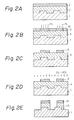
- Figs. 2A to 2E are cross-sectional views showing, in sequence, the pattern formation process according to a two layer resist process of the present invention;
- Fig. 3 is a cross-sectional view showing the down flow etching apparatus used in the pattern formation process of the present invention;
- Fig. 4 is a graph showing the relationship between the Si content in the resist and ratio of the etching rate of said resist; and,
- Fig. 5 is a graph showing the relationship between the energy level of radiation irradiated on the resist layer and the retention rate of the resist.
- In the practice of the present invention, a mixture of the silicon-containing polymer and the addition agent is used as the resist material. The silicon-containing polymer used may be optionally selected from a variety of well-known polymers which satisfy the requirements of the present process. The silicon-containing polymer preferably contains at least one unsaturated bond such as a double or triple bond. Typical examples of such useful silicon-containing polymers includes silylated polyacetylenes such as poly(1-methyl, 2-trimethylsilyl) acetylene, poly[1,2-bis(trimethylsilyl)]acetylene or the like and other silicon-containing polymers such as polymethylsilylmethacrylate, poly trimethylsilylmethacrylate, poly(3-pentamethyldisiloxane)methacrylate and the like, although the present invention is not restricted to these polymers.
- In addition to the double bond-containing polymers, single bond-containing and triple bond-containing polymers are also available. An example of the single bond-containing polymers is


- The addition agent used in admixture with the silicon-containing polymer, as previously described, is preferably an olefin, azide, imide or derivatives thereof. Desirably, the addition agent contains at least one substituent such as aromatic groups, for example, benzene ring, or halogen atoms, for example, chlorine or bromine atoms. Typical examples of useful addition agent include, for example, cinnamoyl chloride, diphenylacetylene, 2,3-diphenylbutadiene, benzyl cinnamate, 2-cinnamoylthiophene,
2,2-dimethoxy-2-phenylacetophenone, 4-azidebenzalcyclohexane, 1,4-diphenylpolybutadiene, 2,6-dichloroquinonechloroimide, 2,6-dibromoquinonechloroimide or chloranil. Other compounds may be used as the addition agent, insofar as they can bond to the polymer upon the addition reaction as a result of exposure to suitable radiation. - The silicon-containing polymer and addition agent may be blended in a wide range of mixing ratios, depending upon factors such as desired results and the like.
- If a single resist layer is desired, the resist material can be coated from a solution thereof onto a surface of the substrate such as a silicon substrate or wafer. Spin coating is preferably used. In addition, if appropriate, vacuum deposition or other coating methods may be used to form the resist layer.
- Alternatively, if a two layer layer resist structure is desired, the above-described resist layer is used as an upper resist layer and is coated after the underlying resist layer "lower resist layer" has been coated on the substrate. The resist material for the lower resist layer is optional and can be selected from the well-known resist materials such as phenol resins, polyimide resins, polystyrene resins, epoxy resins, novolac resins, and the like.
- The single resist layer or upper resist layer is then exposed to a desired pattern of light or radiation which can cause an addition reaction of the polymer and addition agent in the layer. Useful exposure sources include light such as visible light as well as radiation such as ultraviolet radiation, deep ultraviolet radiation, X-rays, electron beams and ion beams.
- After patterning exposure, the resist layer is developed with the down flow etching method. Namely, the resist layer is dry developed with an oxygen-containing etching gas as an active species in the absence of plasma of said gas in an etching chamber positioned apart from a plasma generation chamber. The etching gas is downwardly introduced into said etching chamber, while the plasma of gas is retained in the plasma generation chamber. The etching gas is preferably produced from a mixture of oxygen (O₂) gas and carbon tetrafluoride (CF₄) gas. The resist material in an unexposed area of the resist layer is removed by this development.
- The mechanism of the formation of the resist patterns described above is explained as follows:
- If a mixed resist of the silicon-containing polymer (for example, polyacetylene with a silyl group) and the addition agent (for example, olefin) as the resist layer is exposed to a pattern of light or radiation, the following reaction occurs in an exposed area of the resist layer.

R₁ , R₂ , R₃ , R₄ , R₅ and R₆ may be the same or different and each represents a hydrogen atom or a substituted or unsubstituted alkyl or aryl group, and
n represents a polymerization degree. In the olefin of the above formula, if one or more of R₃ , R₄ , R₅ and R₆ are substituted by, for example, a phenyl group or a halogen atom (see, below), a resistance of the exposed resist to dry etching will be further increased.
- The negative resist pattern thus obtained can be used as a mask in the production of semiconductor devices or other devices. Further, if the resist layer is an upper resist layer of the two layer resist structure, the negative resist pattern can be used as a mask for etching in transferring a pattern of the upper resist layer to the lower resist layer. Etching in such instances can be advantageously carried out by using a dry plasma etching method such as O₂-RIE or ECR (electron cyclotron resonance) etching, although development of the lower resist layer according to the present invention is not restricted to these two methods.
- In connection with the two layer resist process described above, the inventor further found that undesirable shifting of the resulting patterns in the two layer resist process can be effectively prevented if a mixture of high silicon polymer such as polyacetylene having an unsaturated bond in a backbone chain of the recurring unit thereof and at least two silicon atoms on a side chain thereof and addition agent such as ultraviolet absorbing agent is used as the resist material. Useful high silicon polymers include, for example,
poly poly 
- Of course, in addition to these polymers, the polymers containing only one silicon atom on a side chain tereof such as poly 1-(trimethylsilyl)propyne (PTMSP) of the following structural formula:

- The above two layer resist process, according to a preferred embodiment of the present invention, comprises the steps of:
forming a lower resist layer of the organic resist on a substrate to be processed to level topographic features of the substrate; further forming an upper resist layer of the above-described high silicon polymer and ultraviolet absorbing agent over the lower resist layer; patterning the upper resist layer by exposure to ultraviolet radiation; heating the substrate under a reduced pressure to remove the unreacted ultraviolet absorbing agent from the upper resist layer; developing the exposed upper resist layer with the down flow etching method using a O₂/CF₄ gas to obtain a pattern of the upper resist layer; and, etching the lower resist layer, through a mask of the patterned upper resist layer, with anisotropic plasma etching. - According to the process of the present invention, since the exposed silicon-containing resist layer (and the upper resist layer in the two layer resist process) is dry developed without using a developer solution, it is possible to easily produce fine resist patterns of a submicron order. As appreciated from the above description, this is because swelling of the resist layer is avoided due to the absence of the developer solution. Further, since the dry development is carried out in accordance with the down flow etching process, namely, development is not conducted in an atmosphere of O₂ plasma as in a conventional prior art dry development process, but is based on chemical reactions free from ion bombardment, the retention rate of the resist can be remarkably improved. Furthermore, since the silicon-containing polymer, which silicon content can be easily adjusted to a high level, is used as the resist material, if the high silicon polymer is used as the upper resist layer in the two layer resist process, a satisfactorily increased resistance to O₂-RIE can be attained during RIE etching of the lower resist layer. In addition to these advantages, according to the process of the present invention, since pattern shifting of the resist during RIE etching of the lower resist layer is eliminated or reduced to regligible, proportions, the production yield of the devices, and the characteristics thereof, are improved.
- The present invention will be further described with reference to the following examples to which the present invention is not restricted.
- This is an example of the single layer resist process of the present invention and is described with reference to Figs. 1A to 1C and Fig. 3.
- A mixture (2:1) of poly(1-methyl, 2-trimethylsilyl acetylene as the silicon-containing polymer and cinnamoyl chloride as the addition agent was dissolved in xylene to prepare a ca. 1% by weight resist solution, and the resist solution was spin-coated on the substrate. The substrate used herein was a silicon substrate or wafer having cleaned surfaces. After drying, as illustrated in Fig. 1A, a resist
layer 2 having a layer thickness of about 400 nm was formed on an upper surface of thesubstrate 1. - Then, as illustrated in Fig. 1B, the resist
layer 2 was patterning exposed through a mask (not shown) to radiation from an Xe-Hg lamp for about 30 seconds. The contact exposure method was used and an illuminance on a surface of the wafer during exposure was about 5 mW/cm². An exposedarea 12 of the resistlayer 2 showed an increased resistance to dry etching in the next development step. - Development of the exposed resist layer was made in a developing apparatus of Fig. 3. The
wafer 10 was placed in anetching chamber 15 of the developingapparatus 4 and carried with a wafer holder 9. A mixed gas of O₂/CF₄ as a reaction gas was introduced from agas inlet 6 into aplasma generator 14 of theapparatus 4, and exhausted from agas outlet 7 of thesame apparatus 4. During development, a microwave (not shown) from amagnetron 5 was guided into theplasma generation chamber 14, and applied to the downwardly flowing reaction gas to generate plasma of the reaction gas. The plasma itself was stopped with ashield plate 8 for the microwave, but radicals of the atoms constituting the reaction gas (neutral active species) generated together with the gas plasma entered the etching chamber through openings of theshield plate 8. The exposed resist layer (not shown) of thewafer 10 was thus developed with the downwardly flowing plasma-free etching gas. The conditions used in this development step were as follows:Flow rate of O₂: 1000 SCCM, Flow rate of CF₄: 500 SCCM, Pressure: 6 Torr, Power of microwave: 750 W. - As a result of this development, a
negative pattern 12 of the resist layer was formed on the substrate (see Fig. 1C). It was observed that the resist pattern had a retention rate of the resist of about 90% and a resolution of about 0.5µm 1/s (line & space). - Further, the procedure of this example was repeated, except that the mixed gas of O₂/CF₄ was replaced by a mixed gas of O₂/CF₆ and a mixed gas of O₂/NF₃. In each instance, similar results were obtained.
- This is an example of the two layer resist process of the present invention and is described with reference to Figs. 2A to 2E.
- Figure 2A illustrates a cross-section of the two layer resist structure used in this example. The
substrate 1 was a silicon wafer and, as illustrated, contained topographic features. The resist structure was prepared as follows. - The novolac resist: OFPR-800, products of Tokyo Oka Laboratories Limited was spin-coated on an upper surface of the
silicon wafer 1 to level the unevennesses of the wafer surface, and a lower resistlayer 3 having a layer thickness of about 2 µm was thus formed on thesilicon wafer 1. Thereafter, the same resist material as used in Example 1 was spin-coated on the lower resistlayer 3 in accordance with the procedure of Example 1, and an upper resistlayer 2 having a thickness of about 400 nm was produced. - After preparation of the resist structure, the upper resist
layer 2 was patterning exposed as in Example 1 and as shown in Fig. 2B. An exposedarea 12 of the resistlayer 2 on the lower resistlayer 3 showed an increased resistance to dry etching. - The exposed upper resist
layer 2 was then developed as in the development step of Example 1, and as shown in Fig. 2C, anegative pattern 12 of the resist layer was formed as a result of this development. - After the resist
pattern 12 was formed, using this pattern as a mask, the underlying lower resistlayer 3 was dry etched with O₂-RIE to transfer thepattern 12 to the layer 3 (see Fig. 2D). The conditions for this reactive dry etching using O₂ gas were as follows:Flow rate of O₂: 100 SCCM, Pressure: 0.03 Torr, Output: 500 W. layer 13 was selectively etched as a result of this etching, and as shown in Fig. 2E, a negative pattern of the resist 12 plus 13 was eventually formed on the topographic features-bearingsubstrate 1. It was observed that the resist pattern had a thickness of 2 µm and a resolution of 0.5µm 1/s. - The procedure of Example 1 was repeated, except that polytrimethylsilylmethacrylate was used as the silicon-containing polymer and diphenylacetylene as the addition agent, respectively, and finally, a negative pattern of the resist layer was formed on the substrate. It was observed that the resist pattern had a retention rate of the resist of 60%, a resolution of 1 µm, and a sensitivity of 300 mJ.
- The procedure of Example 1 was repeated, except that poly[1,2-bis(trimethylsilyl)]acetylene] was used in place of poly(1-methyl, 2-trimethylsilyl)acetylene, and a negative resist pattern having a retention rate of the resist of 90%, a resolution of 0.5 µm, and a sensitivity of 120 mJ was formed.
- The procedure of Example 1 was repeated, except that poly(3-pentamethyldicyclohexane methacrylate was used in place of poly(1-methyl, 2-trimethylsilyl)acetylene, and a negative resist pattern having a retention rate of the resist of 70%, a resolution of 0.8 µm, and a sensitivity of 200 mJ was formed.
- A mixture (3:2) of poly(1-methyl, 2-trimethylsilyl)acetylene as the silicon-containing polymer and 2,3-diphenylbutadiene as the addition agent was dissolved in xylene to prepare a ca. 1% by weight resist solution. The formation of a resist layer (thickness of about 300 nm), and the exposure and development were performed as in Example 1, and as a result, a negative resist pattern having a retention rate of the resist of 80%, a resolution of 0.5 µm, and a sensitivity of 150 mJ was obtained.
- The same procedure as in Example 6 was repeated, except that diphenylacetylene was used in place of 2,3-diphenylbutadiene, and a negative resist pattern having a retention rate of the resist of 95%, a resolution of 2 µm, and a sensitivity of 230 mJ was obtained.
- The same procedure as in Example 6 was repeated, except that benzyl cinnamate was used in place of 2,3-diphenylbutadiene, and a negative resist pattern having a retention rate of the resist of 75%, a resolution of 0.6 µm, and a sensitivity of 120 mJ was obtained.
- The same procedure as in Example 6 was repeated, except that 2-cinnamoylthiophene was used in place of 2,3-diphenylbutadiene, and a negative resist pattern having a retention rate of the resist of 85%, a resolution of 0.5 µm, and a sensitivity of 200 mJ was obtained.
- The same procedure as in Example 6 was repeated, except that 2,2-dimethoxy-2-phenylacetophenone was used in place of 2,3-diphenylbutadiene, and a negative resist pattern having a retention rate of the resist of 60%, a resolution of 1.0 µm, and a sensitivity of 100 mJ was obtained.
- The same procedure as in Example 6 was repeated, except that 4-azidobenzalcyclohexanone was used in place of 2,3-diphenylbutadiene, and a negative resist pattern having a retention rate of the resist of 75%, a resolution of 0.7 µm, and a sensitivity of 70 mJ was obtained.
- The same procedure as in Example 6 was repeated, except that 1,4-diphenylpolybutadiene was used in place of 2,3-diphenylbutadiene, and a negative resist pattern having a retention rate of the resist of 80%, a resolution of 1.5 µm, and a sensitivity of 200 mJ was obtained.
- A mixture (3:2) of poly trimethylsilyl methacrylate and diphenylacetylene was dissolved in methyl cellosolve acetate to prepare a ca. 8% by weight resist solution. A silicon wafer was spin-coated with this solution, followed by drying to form a resist layer (thickness of about 300 nm). The resist layer was subjected to contact exposure for about 30 seconds by using an Xe-Hg lamp and then baked at about 70°C in vacuum. Development of the exposed resist layer was then carried out under conditions of an O₂ flow rate of 1500 SCCM, a CF₄ flow rate of 300 SCCM, 3 Torr and 750 W on the down flow developing apparatus as in Example 1. As a result, a negative resist pattern having a retention rate of the resist of 50%, a resolution of 1.5 µm, and a sensitivity of 200 mJ was obtained.
- The same procedure as in Example 13 was repeated, except that 2,3-diphenylbutadiene was used in place of diphenylacetylene, and a negative resist pattern having a retention rate of the resist of 60%, a resolution of 0.7 µm, and a sensitivity of 200 mJ was obtained.
- The same procedure as in Example 13 was repeated, except that 4-azidobenzalcyclohexanone was used in place of diphenylacetylene, and a negative resist pattern having a retention rate of the resist of 65%, a resolution of 0.6 µm, and a sensitivity of 80 mJ was obtained.
- This example followed the same procedures as performed in Example 2.
- As shown in Fig. 2A, a
wafer 1 was coated with a lower layer resist OFPR-800, and the resulting lower resist layer (thickness of about 2 µm) 3 was then coated with the resist of Example 6 as an upper resistlayer 2. The upper resistlayer 2 was exposed as in Example 6 (Fig. 2B), developed as in Example 6 (Fig. 2C), and then the lower resistlayer 3 was etched, using the thus obtained negativeupper pattern 12 as a mask, by O₂-RIE (O₂ of 50 SCCM, 0.02 Torr and 500 W) (Fig. 2D). As a result, anegative pattern 13 having a thickness of about 2 µm and having a resolution of 0.5 µm was obtained wherein a dimensional shift from the upper layer resistpattern 12 was 0.1 µm or less (Fig. 2E). - When the negative patterns prepared in Examples 7 to 15 were used as the mask during O₂-RIE, similar results were obtained.
- This example followed the same procedures performed as in Example 2.
- As shown in Fig. 2A, a
wafer 1 was coated with a lower layer resist OFPR-800, and the resulting lower resist layer (thickness of about 2 µm) 3 was then coated with the resist of Example 6 as an upper resistlayer 2. The upper resistlayer 2 was exposed as in Example 6 (Fig. 2B), developed as in Example 6 (Fig. 2C), and then the lower resistlayer 3 was etched, using the thus obtained negativeupper pattern 12 as a mask, by electron cyclone resonance (ECR) etching (O₂ of 10 SCCM, 5 x 10⁻⁴ Torr and 800 W) in place of O₂-RIE (Fig. 2D). As a result, anegative pattern 13 having a thickness of about 2 µm being a resolution of 0.5 µm, was obtained wherein a dimensional shift from the upper layer resistpattern 12 being 0.05 µm or less (Fig. 2E). - In the case that each of the negative patterns prepared in Examples 7 to 15 were used as the mask during ECR etching, similar results were obtained.
- A mixture (3:2) of poly(1-methyl, 2-trimethylsilyl)acetylene as the silicon-containing polymer and 2,6-dichloroquinonchloroimide as the addition agent was mixed to prepare a resist material, and a wafer was spin-coated with the thus prepared resist material to form a resist layer having a thickness of about 300 nm. The resist layer was then subjected to contact exposure by using of an Xe-Hg lamp and baked at about 70°C in vacuum. Development of the exposed resist layer was then carried out under the conditions of a O₂ flow rate of 1000 SCCM, a CF₄ flow rate of 500 SCCM, 6 Torr and 750 W, on the down flow developing apparatus as in Example 1, and as a result, a negative resist pattern having a retention rate of the resist of 90%, a resolution of 0.5 µm, and a sensitivity of 100 mJ was obtained.
- The same procedure as in Example 18 was repeated, except that 2,6-dibromoquinonchloroimide was used as the addition reaction initiator, and a negative resist pattern having a retention rate of the resist of 75%, a resolution of 0.7 µm, and a sensitivity of 200 mJ was obtained.
- The same procedure as in Example 18 was repeated, except that poly[1,2-bis(trimethylsilyl)acetylene was used as the silicon-containing polymer, and a negative resist pattern having a retention rate of the resist of 85%, a resolution of 0.5 µm, and a sensitivity of 100 mJ was obtained.
- The same procedure as in Example 20 was repeated, except that chloranil was used in place of 2,6-dichloroquinonchloroimide, and a negative resist pattern having a retention rate of the resist of 90%, a resolution of 0.6 µm, and a sensitivity of 150 mJ was obtained.
- The same procedure as in Example 18 was repeated, except that polytrimethylsilyl methacrylate was used as the silicon-containing polymer and the development conditions for the down flow development were changed to an O₂ of 1500 SCCM, a CF₄ of 300 SCCM, 3 Torr and 750 W. A negative resist pattern having a retention rate of the resist of 60%, a resolution of 0.6 µm, and a sensitivity of 100 mJ was obtained.
- The same procedure as in Example 22 was repeated, except that chloranil was used in place of 2,6-dichloroquinonchloroimide, and a negative resist pattern having a retention rate of the resist of 70%, a resolution of 0.7 µm, and a sensitivity of 120 mJ was obtained.
- This example followed the procedures as performed in Example 2.
- As shown in Fig. 2A, a
wafer 1 was coated with a lower layer resist OFPR-800, and the resulting lower resist layer (thickness of about 2 µm) 3 was then coated with the resist of Example 18 as an upper resistlayer 2. The upper resistlayer 2 was exposed as in Example 2 (Fig. 2B), developed as in Example 2 (Fig. 2C), and then the lower resistlayer 3 was etched, using the thus obtained uppernegative pattern 12 as a mask, by O₂-RIE (O₂ of 50 SCCM, 0.02 Torr and 500 W) (Fig. 2D). As a result, a negative pattern having a thickness of about 2 µm and having a resolution of 0.5 µm was obtained wherein a dimensional shift from the upper layer resistpattern 12 was 0.1 µm or less (Fig. 2E). - When the negative patterns prepared in Examples 19 to 23 were used as the mask during O₂-RIE, similar results were obtained.
- This example followed the procedures as performed in Example 2.
- As shown in Fig. 2A, a
wafer 1 was coated with a lower layer resist OFPR-800, and the resulting lower resist layer (thickness of about 2 µm) 3 was then coated with the resist of Example 18 as an upper resistlayer 2. The upper resistlayer 2 was exposed as in Example 2 (Fig. 2B), developed as in Example 2 (Fig. 2C), and then the lower resistlayer 3 was etched, using the thus obtained negativeupper pattern 12 as a mask, by electron cyclone resonance (ECR) etching (O₂ of 10 SCCM, 5 x 10⁻⁴ Torr and 800 W) in place of O₂-RIE (Fig. 2D). As a result, anegative pattern 13 having a thickness of about 2 µm and having a resolution of 0.5 µm was obtained wherein a dimensional shift from the upper layer resistpattern 12 was 0.05 µm or less (Fig. 2E). - When the negative patterns prepared in Examples 19 to 23 were used as the mask during ECR etching, similar results were obtained.
- This is an example of the two layer resist process of the present invention.
- The novolac resist: OFPR-800 was spin-coated on an upper surface of the silicon wafer to form a lower resist layer having a thickness of 1.5 µm, the resist layer was then baked at 200°C, and after baking, a mixture (2:1) of poly
4,4,6,6-tetramethyl-4,6-disila-2-heptyne (PTMDSH) and 2,6-dichloroquinone-4-chloroimide (DCQI) was dissolved in xylene and the resulting resist solution was spin-coated on the lower resist layer previous formed, whereby an upper resist layer having a thickness of 0.45 µm was produced. - After preparation of the two layer resist structure, the upper resist layer was subjected to patterning contact exposure by using of a high pressure Xe-Hg lamp as an exposure source. The exposed upper resist layer was then heated at 50°C for 5 minutes under a reduced pressure of 0.05 Torr to remove unreacted DCQI therefrom as a result of vaporization of the same.
- Thereafter, the silicon wafer was placed in a dry etching apparatus. Using this apparatus, the down flow etching was performed as follows: Into a plasma generation chamber wherein the O₂ flow rate of 1000 cc/min, CF₄ flow rate of 500 cc/min and reduced pressure of 6 Torr were maintained, a microwave of output 700 W was introduced to generate a plasma of the mixed gas of O₂ and CF₄. The plasma was then introduced into an etching chamber through a plasma shield plate of metal mesh. Only radicals of the mixed gas were downwardly flown within the etching chamber, and the wafer placed in the etching chamber was place in contact with said radicals, and the upper resist layer thereof was selectively etched in conformity with the pattern of the exposure radiation. A negative pattern of the upper resist layer was obtained on the lower resist layer of the resist structure.
- Subsequent to the patterning of the upper resist layer, using this patterned layer as a mask, the underlying lower resist layer was dry etched with O₂-RIE. The RIE conditions were: an O₂ flow rate of 20 cc/min, a vacuum of 0.08 Torr, and an RF power of 500 W. A pattern of the upper resist layer was exactly transferred to the underlying lower resist layer, no pattern shift was observed.
- A ratio of etching rate of the lower layer resist to the upper layer resist was then determined. The results of determination demonstrated that the ratio of the etching rate in this example was 68 times, while the ratio in another two layer resist structure using poly 1-(trimethylsilyl)propyne (PTMSP) was about 20 times.
- The procedure of Example 26 was repeated, except that PTMDSH was replaced with
poly - The results of the determination of the ratio of the etching rate in these examples are plotted in Fig. 4, together with the results for poly 1-(trimethylsilyl)propyne (PTMSP) used in place of PTMDSH in Example 26. The graph of Fig. 4 clearly shows that the ratio of the etching rate is improved with an increase of the Si content in the silicon-containing polymer as the upper resist layer.
- The procedures of Examples 26 and 27 were repeated to ascertain an effect of the energy of the radiation used in patterning on the retention rate of the resist after exposure, except that a KrF excimer laser (wavelength of 248 nm) was used as the patterning radiation.
- The results plotted in Fig. 5 clearly show that PTMDSH and PTMDSO have an excellent sensitivity, although the sensitivity of PTMSP is also acceptable.
Claims (27)
Applications Claiming Priority (4)
| Application Number | Priority Date | Filing Date | Title |
|---|---|---|---|
| JP60218/88 | 1988-03-16 | ||
| JP63060218A JP2697739B2 (en) | 1988-03-16 | 1988-03-16 | Pattern formation method |
| JP12445/89 | 1989-01-20 | ||
| JP1012445A JP2692227B2 (en) | 1989-01-20 | 1989-01-20 | Method of forming resist pattern |
Publications (3)
| Publication Number | Publication Date |
|---|---|
| EP0333591A2 true EP0333591A2 (en) | 1989-09-20 |
| EP0333591A3 EP0333591A3 (en) | 1991-04-03 |
| EP0333591B1 EP0333591B1 (en) | 1997-10-29 |
Family
ID=26348071
Family Applications (1)
| Application Number | Title | Priority Date | Filing Date |
|---|---|---|---|
| EP89400743A Expired - Lifetime EP0333591B1 (en) | 1988-03-16 | 1989-03-16 | Process for formation of resist patterns |
Country Status (2)
| Country | Link |
|---|---|
| EP (1) | EP0333591B1 (en) |
| KR (1) | KR920004176B1 (en) |
Cited By (2)
| Publication number | Priority date | Publication date | Assignee | Title |
|---|---|---|---|---|
| EP0408334A3 (en) * | 1989-07-14 | 1991-03-27 | Fujitsu Limited | Silicon-containing resists and microlithography using same |
| EP0429270A3 (en) * | 1989-11-20 | 1991-12-27 | Kokusai Electric Co., Ltd. | Continuous etching method and apparatus therefor |
Families Citing this family (9)
| Publication number | Priority date | Publication date | Assignee | Title |
|---|---|---|---|---|
| JP7653908B2 (en) | 2018-11-14 | 2025-03-31 | ラム リサーチ コーポレーション | Methods for making hard masks useful in next generation lithography |
| CN120762258A (en) | 2018-12-20 | 2025-10-10 | 朗姆研究公司 | Dry development of resist |
| TWI869221B (en) | 2019-06-26 | 2025-01-01 | 美商蘭姆研究公司 | Photoresist development with halide chemistries |
| EP4651192A3 (en) | 2020-01-15 | 2026-03-04 | Lam Research Corporation | Underlayer for photoresist adhesion and dose reduction |
| KR102601038B1 (en) | 2020-07-07 | 2023-11-09 | 램 리써치 코포레이션 | Integrated dry processes for patterning radiation photoresist patterning |
| KR102673863B1 (en) | 2020-11-13 | 2024-06-11 | 램 리써치 코포레이션 | Process tool for dry removal of photoresist |
| WO2022125388A1 (en) | 2020-12-08 | 2022-06-16 | Lam Research Corporation | Photoresist development with organic vapor |
| TW202417971A (en) | 2022-07-01 | 2024-05-01 | 美商蘭姆研究公司 | Cyclic development of metal oxide based photoresist for etch stop deterrence |
| CN120958566A (en) | 2023-03-17 | 2025-11-14 | 朗姆研究公司 | Integration of EUV patterned dry development and etching processes in a single processing chamber |
Family Cites Families (1)
| Publication number | Priority date | Publication date | Assignee | Title |
|---|---|---|---|---|
| JPS60238827A (en) * | 1984-05-14 | 1985-11-27 | Nippon Telegr & Teleph Corp <Ntt> | Photosensitive resin composition |
-
1989
- 1989-03-15 KR KR1019890003205A patent/KR920004176B1/en not_active Expired
- 1989-03-16 EP EP89400743A patent/EP0333591B1/en not_active Expired - Lifetime
Cited By (2)
| Publication number | Priority date | Publication date | Assignee | Title |
|---|---|---|---|---|
| EP0408334A3 (en) * | 1989-07-14 | 1991-03-27 | Fujitsu Limited | Silicon-containing resists and microlithography using same |
| EP0429270A3 (en) * | 1989-11-20 | 1991-12-27 | Kokusai Electric Co., Ltd. | Continuous etching method and apparatus therefor |
Also Published As
| Publication number | Publication date |
|---|---|
| KR920004176B1 (en) | 1992-05-30 |
| EP0333591A3 (en) | 1991-04-03 |
| KR890015374A (en) | 1989-10-30 |
| EP0333591B1 (en) | 1997-10-29 |
Similar Documents
| Publication | Publication Date | Title |
|---|---|---|
| US4657843A (en) | Use of polysilsesquioxane without hydroxyl group for forming mask | |
| KR890003264B1 (en) | Formation method of three-layer resist and resist pattern | |
| US5017461A (en) | Formation of a negative resist pattern utilize water-soluble polymeric material and photoacid generator | |
| EP0091651B1 (en) | Method for forming micropattern | |
| EP1061560B1 (en) | Antireflective hard mask compositions | |
| EP0067066B1 (en) | Dry-developing resist composition | |
| US5194364A (en) | Process for formation of resist patterns | |
| JPH0777809A (en) | Pattern formation method using silylation | |
| EP0333591A2 (en) | Process for formation of resist patterns | |
| EP0447111B1 (en) | Resist composition and pattern formation process | |
| US5079131A (en) | Method of forming positive images through organometallic treatment of negative acid hardening cross-linked photoresist formulations | |
| EP1231512B1 (en) | Composition for anti-reflective coating and method for manufacturing semiconductor device | |
| EP0366460A2 (en) | Process for production of semiconductor device | |
| JPH11186243A (en) | Etching method of silicon oxide layer | |
| US5759748A (en) | Method for forming photoresist pattern | |
| EP0274757A2 (en) | Bilayer lithographic process | |
| EP0067067B1 (en) | Dry-developing negative resist composition | |
| KR940011201B1 (en) | Method of forming resist pattern | |
| EP0186798B1 (en) | Top imaged plasma developable resists | |
| US6989227B2 (en) | E-beam curable resist and process for e-beam curing the resist | |
| JPS6360893B2 (en) | ||
| EP0408334A2 (en) | Silicon-containing resists and microlithography using same | |
| EP0250762B1 (en) | Formation of permeable polymeric films or layers via leaching techniques | |
| Reichmanis et al. | Materials Design Considerations for Future Lithographic Technologies | |
| JP2697739B2 (en) | Pattern formation method |
Legal Events
| Date | Code | Title | Description |
|---|---|---|---|
| PUAI | Public reference made under article 153(3) epc to a published international application that has entered the european phase |
Free format text: ORIGINAL CODE: 0009012 |
|
| AK | Designated contracting states |
Kind code of ref document: A2 Designated state(s): DE FR GB |
|
| PUAL | Search report despatched |
Free format text: ORIGINAL CODE: 0009013 |
|
| AK | Designated contracting states |
Kind code of ref document: A3 Designated state(s): DE FR GB |
|
| 17P | Request for examination filed |
Effective date: 19910909 |
|
| 17Q | First examination report despatched |
Effective date: 19920403 |
|
| GRAH | Despatch of communication of intention to grant a patent |
Free format text: ORIGINAL CODE: EPIDOS IGRA |
|
| GRAH | Despatch of communication of intention to grant a patent |
Free format text: ORIGINAL CODE: EPIDOS IGRA |
|
| RBV | Designated contracting states (corrected) |
Designated state(s): FR |
|
| REG | Reference to a national code |
Ref country code: DE Ref legal event code: 8566 |
|
| GRAA | (expected) grant |
Free format text: ORIGINAL CODE: 0009210 |
|
| AK | Designated contracting states |
Kind code of ref document: B1 Designated state(s): FR |
|
| ET | Fr: translation filed | ||
| PLBE | No opposition filed within time limit |
Free format text: ORIGINAL CODE: 0009261 |
|
| STAA | Information on the status of an ep patent application or granted ep patent |
Free format text: STATUS: NO OPPOSITION FILED WITHIN TIME LIMIT |
|
| 26N | No opposition filed | ||
| PGFP | Annual fee paid to national office [announced via postgrant information from national office to epo] |
Ref country code: FR Payment date: 20010313 Year of fee payment: 13 |
|
| PG25 | Lapsed in a contracting state [announced via postgrant information from national office to epo] |
Ref country code: FR Free format text: LAPSE BECAUSE OF NON-PAYMENT OF DUE FEES Effective date: 20021129 |
|
| REG | Reference to a national code |
Ref country code: FR Ref legal event code: ST |