EP0333572A1 - Formatting and utilisation device for induced waves generated by a DC motor, especially for position control - Google Patents
Formatting and utilisation device for induced waves generated by a DC motor, especially for position control Download PDFInfo
- Publication number
- EP0333572A1 EP0333572A1 EP89400689A EP89400689A EP0333572A1 EP 0333572 A1 EP0333572 A1 EP 0333572A1 EP 89400689 A EP89400689 A EP 89400689A EP 89400689 A EP89400689 A EP 89400689A EP 0333572 A1 EP0333572 A1 EP 0333572A1
- Authority
- EP
- European Patent Office
- Prior art keywords
- output
- motor
- pass filter
- low pass
- locked loop
- Prior art date
- Legal status (The legal status is an assumption and is not a legal conclusion. Google has not performed a legal analysis and makes no representation as to the accuracy of the status listed.)
- Granted
Links
Images


Classifications
-
- H—ELECTRICITY
- H02—GENERATION; CONVERSION OR DISTRIBUTION OF ELECTRIC POWER
- H02P—CONTROL OR REGULATION OF ELECTRIC MOTORS, ELECTRIC GENERATORS OR DYNAMO-ELECTRIC CONVERTERS; CONTROLLING TRANSFORMERS, REACTORS OR CHOKE COILS
- H02P7/00—Arrangements for regulating or controlling the speed or torque of electric DC motors
- H02P7/0094—Arrangements for regulating or controlling the speed or torque of electric DC motors wherein the position is detected using the ripple of the current caused by the commutator
-
- G—PHYSICS
- G01—MEASURING; TESTING
- G01P—MEASURING LINEAR OR ANGULAR SPEED, ACCELERATION, DECELERATION, OR SHOCK; INDICATING PRESENCE, ABSENCE, OR DIRECTION, OF MOVEMENT
- G01P3/00—Measuring linear or angular speed; Measuring differences of linear or angular speeds
- G01P3/42—Devices characterised by the use of electric or magnetic means
- G01P3/44—Devices characterised by the use of electric or magnetic means for measuring angular speed
- G01P3/48—Devices characterised by the use of electric or magnetic means for measuring angular speed by measuring frequency of generated current or voltage
-
- H—ELECTRICITY
- H02—GENERATION; CONVERSION OR DISTRIBUTION OF ELECTRIC POWER
- H02P—CONTROL OR REGULATION OF ELECTRIC MOTORS, ELECTRIC GENERATORS OR DYNAMO-ELECTRIC CONVERTERS; CONTROLLING TRANSFORMERS, REACTORS OR CHOKE COILS
- H02P7/00—Arrangements for regulating or controlling the speed or torque of electric DC motors
- H02P7/06—Arrangements for regulating or controlling the speed or torque of electric DC motors for regulating or controlling an individual dc dynamo-electric motor by varying field or armature current
- H02P7/18—Arrangements for regulating or controlling the speed or torque of electric DC motors for regulating or controlling an individual dc dynamo-electric motor by varying field or armature current by master control with auxiliary power
- H02P7/24—Arrangements for regulating or controlling the speed or torque of electric DC motors for regulating or controlling an individual dc dynamo-electric motor by varying field or armature current by master control with auxiliary power using discharge tubes or semiconductor devices
- H02P7/28—Arrangements for regulating or controlling the speed or torque of electric DC motors for regulating or controlling an individual dc dynamo-electric motor by varying field or armature current by master control with auxiliary power using discharge tubes or semiconductor devices using semiconductor devices
- H02P7/285—Arrangements for regulating or controlling the speed or torque of electric DC motors for regulating or controlling an individual dc dynamo-electric motor by varying field or armature current by master control with auxiliary power using discharge tubes or semiconductor devices using semiconductor devices controlling armature supply only
- H02P7/2855—Arrangements for regulating or controlling the speed or torque of electric DC motors for regulating or controlling an individual dc dynamo-electric motor by varying field or armature current by master control with auxiliary power using discharge tubes or semiconductor devices using semiconductor devices controlling armature supply only whereby the speed is regulated by measuring the motor speed and comparing it with a given physical value
Definitions
- the present invention relates to the field of DC motor control devices.
- the object of the present invention is to propose means making it possible to shape the armature current ripples generated by a direct current motor, with a view to subsequent operation by counting for the positioning control of a driven movable member. by the engine.
- the counting of armature current ripples can be used for example to control the positioning of mobile members such mirrors, seats, steering columns, air conditioning control elements ...
- the object of the present invention is to eliminate this drawback.
- the shaping device comprises a low-pass filter placed upstream of the phase-locked loop.
- the shaping device comprises means capable of generating a signal proportional to the f.c.e.m. of the motor and to control the frequency of the phase locked loop on the basis of the signal thus obtained.
- the shaping device comprises means capable of generating a signal proportional to the f.c.e.m. of the motor, a voltage controlled oscillator controlled by the signal proportional to the f.c.e.m. and a switched capacitance filter controlled by the output of the oscillator, placed upstream of the phase locked loop.
- the switched capacitance filter can be a low pass or band pass filter.
- the present invention also relates to a device for exploiting the current ripples generated by a motor direct current which comprises a shaping device incorporating a phase locked loop, as indicated above, means for counting the number of oscillations of the signal coming from the shaping device, and means capable of comparing the number of 'oscillations counted to a reference value to control the engine stop.
- the second input of comparator K2 receives a reference voltage Vref.
- the signal from the comparator K2 is applied to the first input of a phase comparator.
- the second input of the phase comparator receives a set frequency.
- the output signal from the phase comparator is used to control the control circuit of the motor supply voltage.
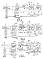
- Each of the three shaping devices illustrated in FIGS. 5, 6 and 7 annexed comprises a phase-locked loop 100 (generally called PLL).
- PLL phase-locked loop 100
- a phase locked loop comprises a phase comparator 110, a low pass filter 120 and a voltage controlled oscillator 130.
- the phase comparator 110 receives the signal to be processed at a first input 111 and a second input 112 the signal from output 132 of oscillator 130.
- the output signal of the phase comparator 110 is applied to the input of the low pass filter 120.
- the output of the low pass filter 120 controls the oscillator 130.
- the output of the phase locked loop 100 is formed by output 132 of the voltage controlled oscillator 130.
- the three shaping devices in accordance with the present invention illustrated respectively in FIGS. 5, 6 and 7 each include a low pass filter 200 and a circuit 300 for extracting a signal representative of the counterelectromotive force of the engine ( fcem).
- the low pass filter 200 and the circuit 300 have their inputs connected to the terminals of the shunt.
- the armature current ripples after filtering in the low pass filter 200, are applied to the input of the phase locked loop 100, more precisely on the input 111 of the phase comparator 110, while the oscillator 130 is driven on its auxiliary input 131 by the signal from the circuit 300.
- the center frequency of the phase locked loop 100 is driven as close as possible to the fundamental of the armature current ripples. This arrangement prevents the phase locked loop 100 from catching on a harmonic.
- the armature current ripples filtered in the low pass filter 200 pass through a switched capacity filter 400 before being applied to the input 111 of the locking loop phase 100.
- the switched capacity filter 400 is controlled by a voltage-controlled oscillator 500, itself controlled at the input by the signal from the fcem extraction circuit 300
- the voltage controlled oscillator 130 of the phase locked loop 100 remains controlled by the signal from the circuit 300.
- the filter with switched capacities 400 can be of the low pass or band pass type.
- This switched capacity filter 400 the cutoff frequency of which is controlled by the VCO 500 in proportion to the frequency of the basic undulations of the armature current, makes it possible to attenuate the harmonics of the signal applied to the input 111 of the locking loop. phase 100.
- the current ripples from the low pass filter 200 also pass through a switched capacitance filter 400 before being applied to the input 111 of the phase-locked loop 100.
- the switched capacity filter 400 is controlled by a VCO 500, itself controlled at the input by the signal from the counter-electromotive force extraction circuit 300.
- the VCO 130 of the phase locked loop 100 is no longer controlled by the signal from the circuit 300, but by a bias voltage Vpol defined to center the frequency of the locked loop 100 on the expected center frequency of the armature current ripples and open the bandwidth of the phase locked loop 100.
- the output of the shaping device corresponds to the output of the phase-locked loop 100, that is to say at the output 132 of the VCO 130.
- the signal obtained at the output 132 of the phase locked loop 100 corresponds to a logic signal coinciding with the periodic component of the armature current generated by the switching of the brushes of the DC motor.
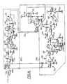
- FIG. 8 corresponds to the first alternative embodiment illustrated in FIG. 5.
- the shaping device illustrated in FIG. 8 comprises an input protection cell comprising a resistor R 202 and a zener diode D 203.
- the voltage V shunt taken from the terminals of the shunt connected in series of the armature of the motor, is applied to a first terminal of the resistor R 202.
- the zener diode D 203 connects the second terminal of the resistor R 202 to the ground.
- the second resistor terminal R 202 drives the low filter pitch 200 and the circuit 300.
- the R 202-D 203 protection cell prevents the application of overvoltage on circuits 200 and 300.
- the circuit 200 comprises connected in series between the output of the protection cell R 202-D 203 and the phase locked loop 100: a subtractor stage 210, a low pass filter 220, an amplifier stage 230, a low pass stage 240 , an amplifier stage 250, a high pass stage 260 and a follower amplifier stage 270.
- the circuit 300 comprises connected between the output of the protection cell R 202-D 203 and the phase locked loop 100: a low pass filter 310, a follower amplifier stage 320, an amplifier stage 330, a subtractor stage 340, a inverter stage 350 and a voltage-current transformation stage 360.
- Stage 320 includes an operational amplifier OP 321.
- the low-pass filter 310 comprises a resistor R 311 and a capacitor C 312.
- the resistor R 311 is connected between the point common to the resistor R 202 and the zener diode D 203, on the one hand, and the non-inverting input of the operational amplifier 321, on the other hand.
- the capacitor C 312 is connected between the non-inverting input of the amplifier OP 321 and the assembly ground.
- the inverting input of the operational amplifier OP 321 is looped back directly to the output of the latter.
- the follower amplifier stage 320 generates at its output a signal representative of the average armature current.
- Stage 210 comprises an operational amplifier OP 211.
- the inverting input thereof is connected to the output of the operational amplifier OP 321 via a link resistor R 212.
- the inverting input of the operational amplifier OP 211 is looped on its output via a resistor R 213.
- the non-inverting input of the operational amplifier OP 211 is connected, on the one hand, by the intermediate of a resistor R 214 in common with the resistor R 202 and the diode D 203, on the other hand, via a resistor R 215 to the ground of the assembly.
- the subtractor stage 210 is used to subtract the average component of the armature current, coming from the follower amplifier stage 320, from the signal taken from the terminals of the shunt.
- the signal from the subtractor stage 210 represents the periodic components of the armature current.
- the low pass filter 220 includes a resistance R 221 and a capacity C 222.
- the amplifier stage 230 includes an operational amplifier OP 231 and two resistors R 232, R 233.
- Resistor R 221 connects the output of the operational amplifier OP 211 to the non-inverting input of the operational amplifier OP 231.
- the inverting input of the operational amplifier OP 231 is connected to the mounting ground via the resistor R 232.
- the inverting input of the operational amplifier OP 231 is looped back to its output by the resistor R 233.
- the low pass filter 240 comprises a resistor R 241 and a capacitor C 242.
- the amplifier stage 250 comprises an operational amplifier OP 251, a resistor R 252 and a variable resistor R 253.
- the resistor R 241 connects the output of the amplifier OP 231 operational at the non-inverting input of the operational amplifier OP 251.
- the capacitor C 242 is connected between the non-inverting input of the operational amplifier OP 251 and the assembly ground.
- the inverting input of the operational amplifier OP 251 is connected to ground mounting via the resistor R 252.
- the inverting input of the operational amplifier OP 251 is looped at its output via the variable resistor R 253.
- the high pass filter 260 comprises a capacity C 261 and a resistor R 262.
- the amplifier stage 270 comprises an operational amplifier OP 271.
- the capacitor C 261 is connected between the output of the operational amplifier OP 251 and the non-inverting input of the operational amplifier OP 271.
- the non-inverting input of the operational amplifier OP 271 is connected to the assembly ground via the resistor R 262.
- the inverting input of the operational amplifier OP 271 is looped back directly to the output of the latter.
- the amplifier stage 330 comprises an operational amplifier OP 331.
- the non-inverting input thereof is connected, on the one hand, to the output of the operational amplifier OP 321 via a resistor R 332, on the other hand, to the assembly ground via a resistor R 333.
- the inverting input of the operational amplifier OP 331 is connected to the mounting ground via a resistor R 334.
- the inverting input of OP 331 is also connected to its output via a adjustable resistance R 335.
- the purpose of the subtractor stage 340 is to subtract from the supply voltage of the motor a signal representing the product of the average induced current by the sum of the shunt resistance and the internal resistance of the direct current motor.
- the subtractor stage 340 includes an operational amplifier OP 341.
- the non-inverting input of the amplifier operational OP 341 receives a signal linked to the supply voltage of the DC motor.
- This non-inverting input of OP 341 is connected to the mounting ground by a resistor R 342.
- the non-inverting input of OP 341 is also connected to the first terminal of a resistor R 343.
- the second terminal of the resistor R 343 is connected to the mounting ground via a cell comprising in parallel a resistor R 344 and a zener diode D 346.
- the second terminal of the resistor R 343 is connected to the supply voltage of the Ualim motor via an R 345 resistor.
- the OP 341 inverting input is connected to the OP 331 output via a resistor R 347.
- the OP 341 inverting input is also looped back to its output via a resistor R 348 .
- the inverter stage 350 comprises a PNP transistor T 351.
- the base of the transistor T 351 is connected to the output of OP 341 by means of a resistor R 352.
- the base of the transistor T 351 is connected to a terminal of positive supply + Vcc via a resistor R 353.
- the transmitter of T 351 is connected to this terminal + Vcc via a resistor R 354.
- the collector of T 351 is connected to the ground of mounting via a potentiometer P 355.
- the current voltage transformation stage 360 includes an operational amplifier OP 361 and an NPN transistor T 362.
- the cursor of potentiometer P 355 is connected to the non-inverting input of OP 361.
- the output of OP 361 attacks the base of transistor T 362.
- the emitter of T 362 is connected to the inverting input of OP 361.
- the transmitter of T 362 is connected to the mounting ground via a resistor R 363.
- the collector of T 362 is connected to the positive supply terminal + Vcc via a resistor R 364.
- the signal representing the armature current ripples generated by the switching of the brushes of the DC motor, filtered by the low pass filter 200 and intended to be applied to the input of the phase locked loop 100, is available at the output of OP 271. Furthermore, the signal representative of the fcem the motor intended to drive the VCO of the phase locked loop 100 is available on the collector of transistor T 362.
- the phase-locked loop 100 is formed of an integrated circuit type LM 565.
- the input 111 of the phase locked loop 100 illustrated in FIGS. 5, 6 and 7 corresponds to terminal 2 of the LM 565 circuit.
- This terminal 2 is connected to the output of OP 271 via a branch comprising in series a resistor R 140 and a capacitor C 141.
- the pilot input, referenced 131 in FIGS. 5, 6 and 7, of the VCO 130 integrated into the phase locking loop 100 corresponds to terminal 8 of the circuit LM 565
- This terminal 8 is connected to the collector of transistor T 362 via resistor R 365. It will also be noted that preferably, as illustrated in FIG.
- the circuit LM 565 which constitutes the phase locked loop 100 has its terminal 1 connected to a positive + Vcc power source, its input terminal 2 connected to the mounting ground via a resistor R 143, its terminal 3 connected to the mounting ground by l intermediary of a resistor R 144, its terminal 7 connected to a positive supply terminal + Vcc by the i ntermediate of a capacity C 145, its terminal 9 connected to a positive power source + Vcc via a capacity C 146 and its terminal 10 connected directly to the same positive power source + Vcc.
- the output of the shaping device is taken from outputs 4 and 5 of the LM 565 circuit connected to each other.
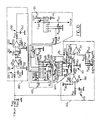
- the shaping device illustrated in FIG. 9 appended comprises an input protection cell R 202-D 203, a low pass filter 200, an f.c.e.m extraction circuit. 300 and a phase-locked loop 100 identical to the first embodiment illustrated in FIG. 8 and previously described. Therefore, these elements will not be described again later.
- the oscillations of the armature current filtered by the circuit 200 are no longer applied directly to the input of the phase locked loop 100, but pass through the filter with switched capacities. 400 before reaching the phase locked loop 100.
- the switched capacity filter 400 is itself controlled by a VCO 500.
- the switched capacity filter 400 can be formed from an integrated circuit type TSG 8550, while the associated VCO 500 is formed from an integrated circuit type AD 537.
- the pilot input of the VCO AD 537 circuit corresponds to terminal 5 thereof.
- This terminal is connected to the output of the operational amplifier OP 341 via a resistive scaling stage 370.
- This stage comprises 3 resistors R 371, R 372 and R 373.
- the resistors R 372 and R 373 are connected in series between the output of OP 341 and the earth.
- Resistor R 371 is connected between the point common to resistors R 372-R 373 and terminal 5 of the VCO 500 circuit.
- VCO AD 537 corresponds to terminal 14 of this circuit.
- the pilot input of the TSG 8550 switched capacity filter corresponds to terminal 7 of this circuit. Therefore, terminal 14 of VCO AD 537 is connected to terminal 7 of the switched capacity filter TSG 8550.
- terminal 13 of the capacity filter TSG 8550 is connected to the output of filter circuit 200, i.e. to the output of OP 271.
- terminal 11 of the switched capacity filter TSG 8550 is connected to the input terminal 2 of the phase-locked loop 100 composed of the circuit LM 565 via the series branch R 140-C 141.
- the VCO 500 driving the switched capacity filter 400 and composed of an AD 537 circuit has its terminal 1 connected to the mounting ground, its terminals 3 and 4 connected in common to the mounting ground by means of an adjustable resistor R 501, its pilot input 5 connected to the ground of the assembly by means of a capacity C 502, its terminal 8 connected to the mass of the assembly, its terminals 9 and 10 interconnected by a potentiometer R 503, its terminals 11 and 12 interconnected by a capacitor C 504, its terminal 13 connected to the cursor of the potentiometer R 503, on the one hand, and connected to its output terminal 14 by a resistor R 505, on the other hand go.
- the switched capacity filter 400 formed by a TSG 8550 circuit has its terminals 1 and 2 connected in common to a positive power supply + Vcc, its terminals 3 and 5 connected in common to the ground of the assembly, its terminal 4 connected to ground via a capacitor C 401 and to its terminal 14 via a resistor R 402, its terminal 6 connected via a resistor R 403 to its terminal 12 and this same terminal 12 via a capacitor C 404 to ground, its terminal 8 connected to the ground of the assembly by means of a resistor R 405, its terminal 9 connected to the ground of the assembly by the intermediate of a resistor R 406, its terminal 10 connected to the mounting ground via a resistor R 407, on the one hand, and connected to the output terminal 11 via an adjustable resistor R 408, on the other hand, its terminal 15 connected to terminal 14 by via a resistor R 409, on the one hand, and to ground via a resistor R 410, on the other hand.
- the resistors R 409 and R 410 determine the amplification factor of an amplifier stage integrated into the TSG 8550 circuit.
- the cell R 402-C 401 serves as a low pass filter for the signal coming from this integrated amplifier stage.
- the cell R 403-C 404 serves as the second low pass filter stage for the signal.
- Resistors R 406, R 407 and R 408 determine the gain of the output amplifier stage of the TSG 8550 circuit.
- this third embodiment in accordance with the present invention comprises a circuit 200 forming a low-pass filter, a circuit 300 serving to extract the f.c.e.m. motor, a phase locked loop 100, a switched capacity filter 400 and a VCO 500 controlling the latter.
- the device further comprises an input protection cell formed by a resistor R 202 and a zener diode D 203 in an identical manner to the embodiments illustrated in FIGS. 8 and 9.
- phase locked loop 100, the switched capacity filter 400 and the pilot VCO 500 can be formed from circuits type LM 565, TSG 8550 and AD 537 in a manner identical to the arrangements previously described with regard to FIG. 9.
- the filter circuit 200 may include a low pass stage 220, an amplifier stage 230, a high pass stage 260, an amplifier stage 250 and a low pass stage 240 similar to the arrangements of the low pass filter 200 illustrated in FIG. 8 and previously described. Note however that the low pass filter 200 illustrated in FIG. 10 differs from the low pass filter 200 illustrated in FIG. 8 by the elimination of the input subtractor stage 210, the suppression of the amplified stage follower cator 270 at output and inversion of stages low pass 240 and high pass 260.
- the circuit 300 for extracting the f.c.e.m. of the motor comprises connected in cascade: a low input pass stage 310 identical to the stage 310 illustrated in FIG. 8, an amplifier stage 380, a scaling stage 390 and a subtractor stage 340 identical to the subtractor stage 340 illustrated in FIG. 8.
- the amplifier stage 380 includes an operational amplifier OP 381.
- the non-inverting input of OP 381 is connected to the output of the low-pass stage 310.
- the inverting input of OP 381 is connected to ground by the resistor R 383 , on the one hand, and at its exit by the resistance R 382, on the other hand.
- the scaling stage 390 includes three resistors R 391, R 392 and R 393.
- Resistors R 391 and R 393 are connected in series between the output of OP 381 and ground. Resistor R 392 connects the common point with resistors R 391, R 393 and the inverting input of OP 341.
- the output of OP 341 attacks via the scaling stage 370 terminal 5 of the pilot VCO circuit AD 537.
- the output terminal 14 of the VCO circuit AD 537 attacks the pilot input 7 of the filter switched capacities TSG 8550.
- the latter receives at its input terminal 13 the signal from the low pass filter 200, more precisely from the output stage 240 of the latter.
- the oscillations of the armature current filtered by the switched capacity filter 400 are available on the output terminal 11 of the latter.
- This output terminal 11 is connected to the input terminal of the phase-locked loop 100 (terminal 2 of the LM 565 circuit) via the R 140-C 141 series branch.
- the phase locked loop 100 is therefore no longer controlled by a signal proportional to the motor fcem, but by a reference potential Vpol applied to its input 131 (terminal 8 of the LM 565 circuit) via a resistor R 147.
- the potential Vpol and the resistance R 147 are determined to center the frequency of the phase locked loop 100 on the central frequency of the undulations of the armature current.
- the device for shaping the armature current undulations described above can be integrated into an operating device comprising means for counting the number of oscillations of the signal from the shaping device (output 132 of VCO 130 in FIGS. 5, 6 and 7, terminals 4 and 5 of the LM 565 circuit according to FIGS. 8, 9 and 10) and means capable of comparing the number of oscillations counted with a reference value to control the engine shutdown.
- the counting means and the comparison means may be identical to the arrangements described in the aforementioned patent application FR-A-2 585 200.
- the electromotive force extraction circuit 300 is switched from a configuration generating a signal proportional to U - (R + r) i into a configuration generating a signal proportional to (R + r) i, U representing the supply voltage of the motor, R the shunt resistance, r the internal resistance of the DC motor and i the mean armature current, when the motor stop signal is validated.
Abstract
Description
La présente invention concerne le domaine des dispositifs de commande de moteurs à courant continu.The present invention relates to the field of DC motor control devices.
La présente invention a pour but de proposer des moyens permettant de mettre en forme les ondulations de courant d'induit générées par un moteur à courant continu, en vue d'une exploitation ultérieure par comptage pour la commande de positionnement d'un organe mobile entraîné par le moteur.The object of the present invention is to propose means making it possible to shape the armature current ripples generated by a direct current motor, with a view to subsequent operation by counting for the positioning control of a driven movable member. by the engine.
On a déjà proposé dans le document FR-A-2 585 200 de détecter la composante périodique du courant d'alimentation d'induit d'un moteur à courant continu et de compter le nombre de périodes de cette composante périodique pour contrôler la position de l'induit et donc la position d'un organe mobile associé à celui-ci. On sait en effet que la composante périodique du courant d'induit est générée par la commutation périodique des balais du moteur. Le nombre d'oscillations du courant d'induit générées à partir d'une position de référence connue est donc directement représentatif de la position instantanée du moteur. Le principe évoqué dans le document FR-A-2 585 200 est séduisant en théorie car il permet d'assurer une commande de positionnement sans exiger de capteurs auxiliaires, tels que capteurs optiques, capteurs à effet Hall ou équivalents classiquement utilisés pour contrôler la position du moteur.It has already been proposed in document FR-A-2 585 200 to detect the periodic component of the armature supply current of a DC motor and to count the number of periods of this periodic component to control the position of the armature and therefore the position of a movable member associated therewith. It is known in fact that the periodic component of the armature current is generated by the periodic switching of the brushes of the motor. The number of armature current oscillations generated from a known reference position is therefore directly representative of the instantaneous position of the motor. The principle mentioned in document FR-A-2 585 200 is attractive in theory because it makes it possible to ensure positioning control without requiring auxiliary sensors, such as optical sensors, Hall effect sensors or the equivalents conventionally used to control the position. of the motor.
Dans le cadre non limitatif du domaine automobile, le comptage des ondulations de courant d'induit peut être utilisé par exemple pour contrôler le positionnement d'organes mobiles tels que rétroviseurs, sièges, colonnes de direction, éléments de contrôle de climatisation...In the non-limiting context of the automotive field, the counting of armature current ripples can be used for example to control the positioning of mobile members such mirrors, seats, steering columns, air conditioning control elements ...
Cependant on constate dans la pratique que le courant d'induit d'un moteur à courant continu est fortement parasité.However, it has been observed in practice that the armature current of a DC motor is strongly parasitized.
On a illustré sur la figure 1 annexée le courant d'induit d'un moteur à courant continu pendant une phase de démarrage et sur la figure 2 annexée, à échelle agrandie, le courant d'induit d'un moteur à courant continu, en régime normal de fonctionnement. Après une phase de démarrage pendant laquelle une pointe de courant est appelée dans le circuit d'induit du moteur, en régime normal de fonctionnement, l'intensité se stabilise à une valeur pratiquement constante, pour une charge mécanique donnée du moteur, une composante périodique générée par la commutation des balais se superposant à la valeur sensiblement constante. La période de cette composante est référencée T sur les figures 1 et 2 annexées.Is illustrated in Figure 1 attached the armature current of a DC motor during a start-up phase and in Figure 2 attached, on an enlarged scale, the armature current of a DC motor, in normal operating conditions. After a start-up phase during which a current surge is called in the armature circuit of the motor, under normal operating conditions, the intensity stabilizes at a practically constant value, for a given mechanical load of the motor, a periodic component generated by the switching of the brushes superimposed on the substantially constant value. The period of this component is referenced T in Figures 1 and 2 attached.
On note à l'examen des figures 1 et 2 que le courant d'induit présente en outre de nombreux parasites aléatoires (harmoniques ou artéfacts). Ces parasites s'ils sont pris en compte par les moyens de comptage conduisent à un calcul erroné des périodes d'oscillations du courant d'induit, donc à un positionnement erroné.It will be noted on examining FIGS. 1 and 2 that the armature current also presents numerous random parasites (harmonics or artefacts). These parasites, if taken into account by the counting means, lead to an erroneous calculation of the periods of oscillations of the armature current, therefore to an erroneous positioning.
On a tenté d'éliminer les parasites superposés au courant d'induit d'un moteur à courant continu à l'aide du circuit illustré sur la figure 3 annexée, en filtrant dans un filtre passe bas, le signal représentatif du courant d'induit prélevé aux bornes d'un shunt connecté en série de l'induit puis en appliquant le signal filtré dans un étage trigger.Attempts have been made to eliminate the parasites superimposed on the armature current of a DC motor using the circuit illustrated in FIG. 3 appended, by filtering in a low pass filter, the signal representative of the armature current. taken from the terminals of a shunt connected in series from the armature and then applying the filtered signal in a trigger stage.
Toutefois, le circuit illustré sur la figure 3 reste très sensible aux harmoniques et aux parasites de forte intensité. Le taux d'erreur dans le comptage des ondulations du courant d'induit, varie entre 1 et 30 % selon l'état du moteur et l'environnement électromagnétique.However, the circuit illustrated in Figure 3 remains very sensitive to harmonics and high intensity noise. The error rate in counting the undulations of the armature current varies between 1 and 30% depending on the state of the motor and the electromagnetic environment.
La présente invention a pour but d'éliminer cet inconvénient.The object of the present invention is to eliminate this drawback.
Elle propose à cet effet d'intégrer une boucle à verrouillage de phase au dispositif de mise en forme des ondulations du courant d'induit générées par un moteur à courant continu.To this end, it proposes integrating a phase locked loop into the device for shaping the armature current ripples generated by a direct current motor.
La Demanderesse a constate que l'utilisation d'une boucle à verrouillage de phase permet de minimiser les erreurs sur le comptage des périodes d'oscillation.The Applicant has noted that the use of a phase locked loop makes it possible to minimize the errors in the counting of the oscillation periods.
Selon une autre caractéristique de l'invention, le dispositif de mise en forme comprend un filtre passe bas placé en amont de la boucle à verrouillage de phase.According to another characteristic of the invention, the shaping device comprises a low-pass filter placed upstream of the phase-locked loop.
Selon une autre caractéristique avantageuse de l'invention, le dispositif de mise en forme comprend des moyens aptes à générer un signal proportionnel à la f.c.e.m. du moteur et à piloter la fréquence de la boucle à verrouillage de phase sur la base du signal ainsi obtenu.According to another advantageous characteristic of the invention, the shaping device comprises means capable of generating a signal proportional to the f.c.e.m. of the motor and to control the frequency of the phase locked loop on the basis of the signal thus obtained.
Selon une autre caractéristique avantageuse de l'invention, le dispositif de mise en forme comprend des moyens aptes à générer un signal proportionnel à la f.c.e.m. du moteur,un oscillateur contrôlé en tension piloté par le signal proportionnel à la f.c.e.m. et un filtre à capacités commutées piloté par la sortie de l'oscillateur, placé en amont de la boucle à verrouillage de phase. Le filtre à capacites commutées peut être un filtre passe bas ou passe bande. Ainsi le signal appliqué à l'entrée de la boucle à verrouillage de phase transite par un filtre dont la fréquence de coupure est pilotée proportionnellement à la vitesse de rotation du moteur puisque la f.c.e.m. est proportionnelle à cette grandeur (fcem = k φ w, k = constante, φ flux, w = vitesse de rotation du moteur). Ainsi les harmoniques sont atténués en entrée de la boucle à verrouillage de phase, quelle que soit la vitesse de rotation du moteur.According to another advantageous characteristic of the invention, the shaping device comprises means capable of generating a signal proportional to the f.c.e.m. of the motor, a voltage controlled oscillator controlled by the signal proportional to the f.c.e.m. and a switched capacitance filter controlled by the output of the oscillator, placed upstream of the phase locked loop. The switched capacitance filter can be a low pass or band pass filter. Thus the signal applied to the input of the phase locked loop passes through a filter whose cutoff frequency is controlled in proportion to the speed of rotation of the motor since the f.c.e.m. is proportional to this quantity (fcem = k φ w, k = constant, φ flux, w = motor rotation speed). Thus the harmonics are attenuated at the input of the phase-locked loop, whatever the speed of rotation of the motor.
La présente invention concerne également un dispositif d'exploitation des ondulations de courant générées par un moteur a courant continu qui comprend un dispositif de mise en forme incorporant une boucle à verrouillage de phase, comme indiqué précédemment, des moyens de comptage du nombre d'oscillations du signal issu du dispositif de mise en forme, et des moyens aptes à comparer le nombre d'oscillations compté à une valeur de référence pour contrôler l'arrêt du moteur.The present invention also relates to a device for exploiting the current ripples generated by a motor direct current which comprises a shaping device incorporating a phase locked loop, as indicated above, means for counting the number of oscillations of the signal coming from the shaping device, and means capable of comparing the number of 'oscillations counted to a reference value to control the engine stop.
La Demanderesse tient à mentionner que le document Elektronik n° 25, pages 71-72 (unkonventionelle Drehzahlmessung und -regelung bei Gleichstrommotoren) décrit un circuit d'asservissement pour moteur à courant continu qui présente une certaine analogie structurelle avec la présente invention. Le circuit proposé dans ce document est illustré sur la figure 4 annexée. On aperçoit sur cette figure 4 un shunt connecté en série de l'induit du moteur à courant continu. Un comparateur K₁ reçoit sur ses entrées respectivement la tension d'alimentation du moteur et la tension prélevée aux bornes du shunt. La tension issue du comparateur K₁ est dirigée vers un oscillateur commandé en tension (VCO) qui pilote un filtre à capacités commutées. Le signal issu de ce filtre est appliqué sur la première entrée d'un second comparateur K₂. La seconde entrée du comparateur K₂ reçoit une tension de référence Vref. Le signal issu du comparateur K₂ est appliqué sur la première entrée d'un comparateur de phase. La seconde entrée du comparateur de phase reçoit une fréquence de consigne. Le signal de sortie du comparateur de phase sert à piloter le circuit d'asservissement de la tension d'alimentation du moteur.The Applicant wishes to mention that the document Elektronik n ° 25, pages 71-72 (unkonventionelle Drehzahlmessung und -regelung bei Gleichstrommotoren) describes a control circuit for a DC motor which has a certain structural analogy with the present invention. The circuit proposed in this document is illustrated in Figure 4 attached. This figure 4 shows a shunt connected in series with the armature of the DC motor. A comparator K₁ receives on its inputs respectively the supply voltage of the motor and the voltage taken from the terminals of the shunt. The voltage from the comparator K₁ is directed to a voltage controlled oscillator (VCO) which controls a filter with switched capacities. The signal from this filter is applied to the first input of a second comparator K₂. The second input of comparator K₂ receives a reference voltage Vref. The signal from the comparator K₂ is applied to the first input of a phase comparator. The second input of the phase comparator receives a set frequency. The output signal from the phase comparator is used to control the control circuit of the motor supply voltage.
On notera cependant que le document Elektronik précité n'enseigne pas d'utiliser une boucle à verrouillage de phase : qu'il n'enseigne pas de compter les ondulations de courant d'induit d'un moteur à courant continu ; qu'un tel comptage d'ondulations de courant d'induit ne présenterait d'ailleurs aucun intérêt dans le contexte du document Elektronik puisque ce document a précisément pour but de réguler la vitesse de rotation du moteur.Note, however, that the aforementioned Elektronik document does not teach to use a phase locked loop: that it does not teach to count the armature current ripples of a DC motor; that such a counting of armature current ripples would also be of no interest in the context of the Elektronik document since the purpose of this document is precisely to regulate the speed of rotation of the motor.
D'autres caractéristiques, buts et avantages de la présente invention apparaîtront à la lecture de la description détaillée qui va suivre, et en regard des dessins annexés, donnés à titre d'exemples non limitatifs et sur lesquels :
- - les figures 1 et 2 représentent, comme indiqué précédemment, le courant d'induit d'un moteur à courant continu,
- -les figure 3 et 4 précédemment décrites illustrent l'état de la technique,
- -les figures 5, 6 et 7 représentent, sous forme de blocs fonctionnels schématiques, trois variantes de réalisation d'un dispositif de mise en forme conforme à la présente invention, et
- -les figures 8, 9 et 10 représentent les schémas détaillés de ces trois variantes de réalisation respectivement.
- FIGS. 1 and 2 represent, as indicated above, the armature current of a DC motor,
- FIGS. 3 and 4 previously described illustrate the state of the art,
- FIGS. 5, 6 and 7 show, in the form of schematic functional blocks, three alternative embodiments of a shaping device according to the present invention, and
- FIGS. 8, 9 and 10 represent the detailed diagrams of these three alternative embodiments respectively.
Chacun des trois dispositifs de mise en forme illustrés les figures 5, 6 et 7 annexées comprend une boucle à verrouillage de phase 100 (dénommée généralement PLL).Each of the three shaping devices illustrated in FIGS. 5, 6 and 7 annexed comprises a phase-locked loop 100 (generally called PLL).
On rappelle qu'une boucle à verrouillage de phase comprend un comparateur de phase 110, un filtre passe bas 120 et un oscillateur commandé en tension 130. Le comparateur de phase 110 reçoit sur une première entrée 111 le signal à traiter et sur une seconde entrée 112 le signal issu de la sortie 132 de l'oscillateur 130.It will be recalled that a phase locked loop comprises a
Le signal de sortie du comparateur de phase 110 est appliqué à l'entrée du filtre passe bas 120. La sortie du filtre passe bas 120 pilote l'oscillateur 130. La sortie de la boucle à verrouillage de phase 100 est formée par la sortie 132 de l'oscillateur commandé en tension 130.The output signal of the
Sur les figures 5, 6 et 7 annexees, on a représenté schématiquement un moteur à courant continu et un shunt connecté en série de son induit. La tension prélevée aux bornes du shunt est ainsi directement proportionnelle au courant d'induit du moteur à courant continu.In Figures 5, 6 and 7 attached, there is shown schematically a DC motor and a shunt connected in series with its armature. The voltage taken from the shunt terminals is thus directly proportional to the armature current of the DC motor.
Les trois dispositifs de mise en forme conformes à la présente invention illustrés respectivement sur les figures 5, 6 et 7 comprennent chacun un filtre passe bas 200 et un circuit 300 d'extraction d'un signal représentatif de la force contre-électromotrice du moteur (f.c.e.m.). Le filtre passe bas 200 et le circuit 300 ont leurs entrées connectées aux bornes du shunt.The three shaping devices in accordance with the present invention illustrated respectively in FIGS. 5, 6 and 7 each include a
Selon la première variante de réalisation illustrée sur la figure 5 annexée les ondulations de courant d'induit, après filtrage dans le filtre passe bas 200, sont appliquées à l'entrée de la boucle à verrouillage de phase 100, plus précisément sur l'entrée 111 du comparateur de phase 110, tandis que l'oscillateur 130 est piloté sur son entrée auxiliaire 131 par le signal issu du circuit 300. Ainsi, la fréquence centrale de la boucle à verrouillage de phase 100 est pilotée au plus près de la fondamentale des ondulations du courant d'induit. Cette disposition évite un accrochage de la boucle à verrouillage de phase 100 sur une harmonique.According to the first alternative embodiment illustrated in FIG. 5 appended, the armature current ripples, after filtering in the
Selon la seconde variante de réalisation illustrée sur la figure 6 annexée, les ondulations de courant d'induit filtrées dans le filtre passe bas 200 transitent par un filtre à capacités commutées 400 avant d'être appliqué à l'entrée 111 de la boucle à verrouillage de phase 100. Le filtre à capacités commutées 400 est piloté par un oscillateur commandé en tension 500, lui-même piloté en entrée par le signal issu du circuit 300 d'extraction de f.c.e.m.According to the second variant embodiment illustrated in FIG. 6 appended, the armature current ripples filtered in the
L'oscillateur commandé en tension 130 de la boucle à verrouillage de phase 100 reste piloté par le signal issu du circuit 300.The voltage controlled
Le filtre a capacités commutées 400 peut être du type passe bas ou passe bande. Ce filtre à capacités commutées 400, dont la fréquence de coupure est pilotée par le VCO 500 proportionnellement à la fréquence des ondulations de base du courant d'induit permet d'atténuer les harmoniques du signal appliqué sur l'entrée 111 de la boucle à verrouillage de phase 100.The filter with switched
Dans le cadre de la troisième variante de réalisation conforme à la présente invention illustrée sur la figure 7, les ondulations de courant issues du filtre passe bas 200 transitent également par un filtre à capacites commutées 400 avant d'être appliquées à l'entrée 111 de la boucle à verrouillage de phase 100. De même, le filtre à capacités commutées 400 est piloté par un VCO 500, lui-même piloté en entrée par le signal issu du circuit d'extraction de force contre-électromotrice 300. Par contre, dans le cadre de ce troisième mode de réalisation, le VCO 130 de la boucle à verrouillage de phase 100 n'est plus piloté par le signal issu du circuit 300, mais par une tension de polarisation Vpol définie pour centrer la fréquence de la boucle à verrouillage de phase 100 sur la fréquence centrale attendue des ondulations du courant d'induit et ouvrir la bande passante de la boucle à verrouillage de phase 100.In the context of the third variant embodiment according to the present invention illustrated in FIG. 7, the current ripples from the
Dans les trois modes de réalisation illustrés sur les figures 5, 6 et 7, la sortie du dispositif de mise en forme correspond à la sortie de la boucle à verrouillage de phase 100, c'est-à-dire à la sortie 132 du VCO 130. En effet, le signal obtenu à la sortie 132 de la boucle à verrouillage de phase 100 correspond à un signal logique coïncidant avec la composante périodique du courant d'induit générée par la commutation des balais du moteur à courant continu.In the three embodiments illustrated in FIGS. 5, 6 and 7, the output of the shaping device corresponds to the output of the phase-locked
On va maintenant décrire dans le détail le mode de réalisation illustré sur la figure 8 annexée, qui correspond à la première variante de réalisation illustrée sur la figure 5.We will now describe in detail the embodiment illustrated in FIG. 8 appended, which corresponds to the first alternative embodiment illustrated in FIG. 5.
Le dispositif de mise en forme illustré sur la figure 8 comprend une cellule de protection en entrée comprenant une résistance R 202 et une diode zener D 203. La tension V shunt, prélevée aux bornes du shunt connecté en série de l'induit du moteur, est appliquée sur une première borne de la résistance R 202. La diode zener D 203 relie la seconde borne de la résistance R 202 à la masse. De plus, la seconde borne de la résistance R 202 attaque le filtre basse pas 200 et le circuit 300.The shaping device illustrated in FIG. 8 comprises an input protection cell comprising a resistor R 202 and a zener diode D 203. The voltage V shunt, taken from the terminals of the shunt connected in series of the armature of the motor, is applied to a first terminal of the resistor R 202. The zener diode D 203 connects the second terminal of the resistor R 202 to the ground. In addition, the second resistor terminal R 202 drives the
La cellule de protection R 202-D 203 évite l'application de surtension sur les circuits 200 et 300.The R 202-D 203 protection cell prevents the application of overvoltage on
Le circuit 200 comprend connectés en série entre la sortie de la cellule de protection R 202-D 203 et la boucle à verrouillage de phase 100 : un étage soustracteur 210, un filtre passe bas 220, un étage amplificateur 230, un étage passe bas 240, un étage amplificateur 250, un étage passe haut 260 et un étage amplificateur suiveur 270.The
Le circuit 300 comprend connectés entre la sortie de la cellule de protection R 202-D 203 et la boucle à verouillage de phase 100 : un filtre passe bas 310, un étage amplificateur suiveur 320, un étage amplificateur 330, un étage soustracteur 340, un étage inverseur 350 et un étage de transformation tension-courant 360.The
L'étage 320 comprend un amplificateur opérationnel OP 321.
Le filtre passe bas 310 comprend une résistance R 311 et une capacité C 312. La résistance R 311 est reliée entre le point commun à la résistance R 202 et la diode zener D 203, d'une part, et l'entrée non inverseuse de l'amplificateur opérationnel 321, d'autre part. La capacité C 312 est reliée entre l'entrée non inverseuse de l'amplificateur OP 321 et la masse du montage.The low-
L'entrée inverseuse de l'amplificateur opérationnel OP 321 est rebouclée directement sur la sortie de ce dernier. Ainsi l'etage amplificateur suiveur 320 génère à sa sortie un signal représentatif du courant d'induit moyen.The inverting input of the operational amplifier OP 321 is looped back directly to the output of the latter. Thus the
L'étage 210 comprend un amplificateur opérationnel OP 211. L'entrée inverseuse de celui-ci est réliée à la sortie de l'amplificateur opérationnel OP 321 par l'intermédiaire d'une résistance de liaison R 212.
L'entrée inverseuse de l'amplificateur opérationnel OP 211 est bouclée sur sa sortie par l'intermédiaire d'une résistance R 213. L'entrée non inverseuse de l'amplificateur opérationnel OP 211 est reliée, d'une part, par l'intermédiaire d'une résistance R 214 au point commun à la résistance R 202 et à la diode D 203, d'autre part, par l'intermédiaire d'une résistance R 215 à la masse du montage.The inverting input of the
L'étage soustracteur 210 sert à retrancher la composante moyenne du courant d'induit, issue de l'étage amplificateur suiveur 320, du signal prélevé aux bornes du shunt. Ainsi le signal issu de l'étage soustracteur 210 représente les composantes périodiques du courant d'induit.The
Le filtre passe bas 220 comprend une résistance R 221 et une capacité C 222.The
L'étage amplificateur 230 comprend un amplificateur opérationnel OP 231 et deux résistances R 232, R 233.The
La résistance R 221 relie la sortie de l'amplificateur opérationnel OP 211 a l'entrée non inverseuse de l'amplificateur opérationnel OP 231.Resistor R 221 connects the output of the
L'entrée inverseuse de l'amplificateur opérationnel OP 231 est reliée à la masse du montage par l'intermédiaire de la résistance R 232. De plus, l'entrée inverseuse de l'amplificateur opérationnel OP 231 est rebouclée sur sa sortie par l'intermédiaire de la résistance R 233.The inverting input of the operational amplifier OP 231 is connected to the mounting ground via the resistor R 232. In addition, the inverting input of the operational amplifier OP 231 is looped back to its output by the resistor R 233.
Le filtre passe bas 240 comprend une résistance R 241 et une capacité C 242. L'étage amplificateur 250 comprend un amplificateur opérationnel OP 251, une résistance R 252 et une résistance variable R 253. La résistance R 241 relie la sortie de l'amplificateur opérationnel OP 231 à l'entrée non inverseuse de l'amplificateur opérationnel OP 251. La capacité C 242 est reliée entre l'entrée non inverseuse de l'amplificateur opérationnel OP 251 et la masse du montage. L'entrée inverseuse de l'amplificateur opérationnel OP 251 est reliée à la masse du montage par l'intermédiaire de la résistance R 252. L'entrée inverseuse de l'amplificateur opérationnel OP 251 est bouclée sur sa sortie par l'intermédiaire de la résistance variable R 253.The
Le filtre passe haut 260 comprend une capacité C 261 et une résistance R 262.The
L'étage amplificateur 270 comprend un amplificateur opérationnel OP 271.The
La capacité C 261 est reliée entre la sortie de l'amplificateur opérationnel OP 251 et l'entrée non inverseuse de l'amplificateur opérationnel OP 271.The
L'entrée non inverseuse de l'amplificateur opérationnel OP 271 est reliée à la masse du montage par l'intermédiaire de la résistance R 262.The non-inverting input of the operational amplifier OP 271 is connected to the assembly ground via the resistor R 262.
L'entrée inverseuse de l'amplificateur opérationnel OP 271 est rebouclée directement sur la sortie de ce dernier.The inverting input of the operational amplifier OP 271 is looped back directly to the output of the latter.
L'étage amplificateur 330 comprend un amplificateur opérationnel OP 331. L'entrée non inverseuse de celui-ci est reliée, d'une part, à la sortie de l'amplificateur opérationnel OP 321 par l'intermediaire d'une résistance R 332, d'autre part, à la masse du montage par l'intermédiaire d'une résistance R 333.The
L'entrée inverseuse de l'amplificateur opérationnel OP 331 est reliée à la masse du montage par l'intermédiaire d'une résistance R 334. L'entrée inverseuse de OP 331 est par ailleurs reliée à sa sortie par l'intermédiaire d'une résistance ajustable R 335.The inverting input of the operational amplifier OP 331 is connected to the mounting ground via a resistor R 334. The inverting input of OP 331 is also connected to its output via a adjustable resistance R 335.
L'étage soustracteur 340 a pour but de soustraire de la tension d'alimentation du moteur un signal représentant le produit du courant moyen d'induit par la somme de la résistance du shunt et de la résistance interne du moteur à courant continu.The purpose of the
L'étage soustracteur 340 comprend un amplificateur opérationnel OP 341. L'entrée non inverseuse de l'amplificateur opérationnel OP 341 reçoit un signal lié à la tension d'alimentation du moteur à courant continu.The
Cette entrée non inverseuse de OP 341 est reliée à la masse du montage par une résistance R 342. L'entrée non inverseuse de OP 341 est par ailleurs reliée à la première borne d'une résistance R 343. La seconde borne de la résistance R 343 est reliée à la masse du montage par l'intermédiaire d'une cellule comprenant en parallèle une résistance R 344 et une diode zener D 346. De plus, la seconde borne de la résistance R 343 est reliée à la tension d'alimentation du moteur Ualim par l'intermédiaire d'une résistance R 345.This non-inverting input of OP 341 is connected to the mounting ground by a resistor R 342. The non-inverting input of OP 341 is also connected to the first terminal of a resistor R 343. The second terminal of the resistor R 343 is connected to the mounting ground via a cell comprising in parallel a resistor R 344 and a
L'entrée inverseuse de OP 341 est reliée à la sortie de OP 331 par l'intermédiaire d'une résistance R 347. L'entrée inverseuse de OP 341 est de plus rebouclée sur sa sortie par l'intermédiaire d'une résistance R 348.The OP 341 inverting input is connected to the OP 331 output via a resistor R 347. The OP 341 inverting input is also looped back to its output via a resistor R 348 .
L'étage inverseur 350 comprend un transistor PNP T 351. La base du transistor T 351 est reliée à la sortie de OP 341 par l'intermédiaire d'une résistance R 352. La base du transistor T 351 est reliée à une borne d'alimentation positive +Vcc par l'intermédiaire d'une résistance R 353. L'émetteur de T 351 est relié à cette borne +Vcc par l'intermédiaire d'une résistance R 354. Le collecteur de T 351 est relié à la masse du montage par l'intermédiaire d'un potentiomètre P 355. L'étage de transformation tension courant 360 comprend un amplificateur opérationnel OP 361 et un transistor NPN T 362.The
Le curseur du potentiomètre P 355 est relié à l'entrée non inverseuse de OP 361. La sortie de OP 361 attaque la base du transistor T 362. L'émetteur de T 362 est relié à l'entrée inverseuse de OP 361. De plus, l'émetteur de T 362 est relié à la masse du montage par l'intermédiaire d'une résistance R 363. Le collecteur de T 362 est relié à la borne d'alimentation positive +Vcc par l'intermédiaire d'une résistance R 364.The cursor of potentiometer P 355 is connected to the non-inverting input of
Le signal représentant les ondulations de courant d'induit générées par la commutation des balais du moteur à courant continu, filtré par le filtre passe bas 200 et destiné à être appliqué à l'entrée de la boucle à verrouillage de phase 100, est disponible sur la sortie de OP 271. Par ailleurs, le signal représentatif de la f.c.e.m. du moteur destiné à piloter le VCO de la boucle à verrouillage de phase 100 est disponible sur le collecteur du transistor T 362.The signal representing the armature current ripples generated by the switching of the brushes of the DC motor, filtered by the
Selon le mode de réalisation illustré sur la figure 8 annexée, la boucle à verrouillage de phase 100 est formée d'un circuit intégré type LM 565.According to the embodiment illustrated in FIG. 8 appended, the phase-locked
L'entrée 111 de la boucle à verrouillage de phase 100 illutrée sur les figures 5, 6 et 7 correspond à la borne 2 du circuit LM 565. Cette borne 2 est reliée à la sortie de OP 271 par l'intermédiaire d'une branche comprenant en série une résistance R 140 et une capacité C 141. L'entrée pilote, référencée 131 sur les figures 5, 6 et 7, du VCO 130 intégré à la boucle de verrouillage de phase 100 correspond à la borne 8 du circuit LM 565. Cette borne 8 est reliée au collecteur du transistor T 362 par l'intermédiaire de la résistance R 365. On notera par ailleurs que de préférence, comme illustré sur la figure 8 annexée, le circuit LM 565 qui constitue la boucle à verrouillage de phase 100 a sa borne 1 reliée à une source d'alimentation positive +Vcc, sa borne 2 d'entrée reliée à la masse du montage par l'intermédiaire d'une résistance R 143, sa borne 3 reliée à la masse du montage par l'intermédiaire d'une résistance R 144, sa borne 7 reliée à une borne d'alimentation positive +Vcc par l'intermédiaire d'une capacité C 145, sa borne 9 reliée à une source d'alimentation positive +Vcc par l'intermédiaire d'une capacité C 146 et sa borne 10 reliée directement à la même source d'alimentation positive +Vcc.The
La sortie du dispositif de mise en forme est prélevée sur les sorties 4 et 5 du circuit LM 565 reliées entre elles.The output of the shaping device is taken from
On va maintenant décrire le second mode de réalisation conforme à la présente invention illustré sur la figure 9 annexée.We will now describe the second embodiment according to the present invention illustrated in Figure 9 attached.
Le dispositif de mise en forme illustré sur la figure 9 annexée comprend une cellule de protection d'entrée R 202-D 203, un filtre passe bas 200, un circuit d'extraction de f.c.e.m. 300 et une boucle à verrouillage de phase 100 identiques au premier mode de réalisation illustré sur la figure 8 et précédemment décrit. De ce fait, ces éléments ne seront pas décrits à nouveau par la suite.The shaping device illustrated in FIG. 9 appended comprises an input protection cell R 202-D 203, a
Cependant selon le second mode de réalisation illustré sur la figure 9 les oscillations du courant d'induit filtrées par le circuit 200 ne sont plus appliquées directement à l'entrée de la boucle à verrouillage de phase 100, mais transitent par le filtre à capacités commutées 400 avant de parvenir à la boucle à verrouillage de phase 100.However according to the second embodiment illustrated in FIG. 9, the oscillations of the armature current filtered by the
Comme indiqué précédemment en regard de la figure 6, le filtre à capacités commutées 400 est lui-même piloté par un VCO 500.As indicated above with reference to FIG. 6, the switched
Le filtre à capacités commutées 400 peut être formé d'un circuit intégré type TSG 8550, alors que le VCO 500 associé est formé d'un circuit intégré type AD 537.The switched
L'entrée pilote du circuit VCO AD 537 correspond à la borne 5 de celui-ci. Cette borne est reliée à la sortie de l'amplificateur opérationnel OP 341 par l'intermédiaire d'un étage de mise à l'échelle résistif 370. Cet étage comprend 3 résistances R 371, R 372 et R 373. Les résistances R 372 et R 373 sont connectées en série entre la sortie de OP 341 et la masse. La résistance R 371 est reliée entre le point commun aux résistances R 372-R 373 et la borne 5 du circuit VCO 500.The pilot input of the VCO AD 537 circuit corresponds to
La sortie du VCO AD 537 correspond à la borne 14 de ce circuit. L'entrée pilote du filtre à capacités commutées TSG 8550 correspond à la borne 7 de ce circuit. De ce fait, la borne 14 du VCO AD 537 est reliée à la borne 7 du filtre à capacités commutées TSG 8550.The output of VCO AD 537 corresponds to
L'entrée du filtre à capacités commutées 400 correspond à la borne 13 de ce circuit. De ce fait, la borne 13 du filtre à capacités commutées TSG 8550 est reliée à la sortie du circuit de filtre 200, c'est-à-dire à la sortie de OP 271.The input of the switched
Enfin, la sortie du filtre à capacités commutées TSG 8550 est formée par la borne 11 de ce circuit. De ce fait, la borne 11 du filtre à capacités commutées TSG 8550 est reliée à la borne 2 d'entrée de la boucle à verrouillage de phase 100 composée du circuit LM 565 par l'intermédiaire de la branche série R 140-C 141.Finally, the output of the TSG 8550 switched capacity filter is formed by
On notera par ailleurs que de préférence, le VCO 500 pilotant le filtre à capacités commutées 400 et composé d'un circuit AD 537 a sa borne 1 reliée à la masse du montage, ses bornes 3 et 4 reliées en commun à la masse du montage par l'intermédiaire d'une résistance ajustable R 501, son entrée pilote 5 reliée à la masse du montage par l'intermédiaire d'une capacité C 502, sa borne 8 reliée à la masse du montage, ses bornes 9 et 10 interconnectées par un potentiomètre R 503, ses bornes 11 et 12 interconnectées par une capacité C 504, sa borne 13 reliée au curseur du potentiomètre R 503, d'une part, et reliée à sa borne de sortie 14 par une résistance R 505, d'autre part.It will also be noted that preferably, the
De même le filtre à capacités commutées 400 formé d'un circuit TSG 8550 a ses bornes 1 et 2 reliées en commun à une source d'alimentation positive +Vcc, ses bornes 3 et 5 reliées en commun à la masse du montage, sa borne 4 reliée à la masse par l'intermédiaire d'une capacité C 401 et à sa borne 14 par l'intermédiaire d'une résistance R 402, sa borne 6 reliée par l'intermédiaire d'une résistance R 403 à sa borne 12 et cette même borne 12 par l'intermédiaire d'une capacité C 404 à la masse, sa borne 8 reliée à la masse du montage par l'intermédiaire d'une résistance R 405, sa borne 9 connectée à la masse du montage par l'intermédiaire d'une résistance R 406, sa borne 10 reliée à la masse du montage par l'intermédiaire d'une résistance R 407, d'une part, et reliée à la borne 11 de sortie par l'intermédiaire d'une résistance ajustable R 408, d'autre part, sa borne 15 reliée à la borne 14 par l'intermédiaire d'une résistance R 409, d'une part, et à la masse par l'intermédiaire d'une résistance R 410, d'autre part.Similarly, the switched
Les résistances R 409 et R 410 déterminent le facteur d'amplification d'un étage amplificateur intégré au circuit TSG 8550. La cellule R 402-C 401 sert de filtre passe bas pour le signal issu de cet étage amplificateur intégré. La cellule R 403-C 404 sert de second étage filtre passe bas pour le signal. Les résistances R 406, R 407 et R 408 déterminent le gain de l'étage amplificateur de sortie du circuit TSG 8550.The resistors R 409 and R 410 determine the amplification factor of an amplifier stage integrated into the TSG 8550 circuit. The cell R 402-C 401 serves as a low pass filter for the signal coming from this integrated amplifier stage. The cell R 403-C 404 serves as the second low pass filter stage for the signal.
On va maintenant décrire le troisième mode de réalisation conforme à la présente invention illustré sur la figure 10 annexée.We will now describe the third embodiment according to the present invention illustrated in Figure 10 attached.
Comme indiqué précédemment en regard de la figure 7, ce troisième mode de réalisation conforme à la présente invention comprend un circuit 200 formant filtre passe bas, un circuit 300 servant à extraire la f.c.e.m. du moteur, une boucle à verrouillage de phase 100, un filtre à capacités commutées 400 et un VCO 500 pilotant ce dernier. Le dispositif comprend de plus une cellule de protection en entrée formée d'une résistance R 202 et d'une diode zener D 203 de façon identique aux modes de réalisation illustrés sur les figures 8 et 9.As indicated above with reference to FIG. 7, this third embodiment in accordance with the present invention comprises a
La boucle à verrouillage de phase 100, le filtre à capacités commutées 400 et le VCO pilote 500 peuvent être formés de circuits type LM 565, TSG 8550 et AD 537 de façon identique aux dispositions précédemment décrites en regard de la figure 9.The phase locked
Le circuit filtre 200 peut comprendre un étage passe bas 220, un étage amplificateur 230, un étage passe haut 260, un étage amplificateur 250 et un étage passe bas 240 similaires aux dispositions du filtre passe bas 200 illustré sur la figure 8 et précédemment décrit. On notera cependant que le filtre passe bas 200 illustré sur la figure 10 diffère du filtre passe bas 200 illustré sur la figure 8 par la suppression de l'étage soustracteur d'entrée 210, la suppression de l'étage amplifi cateur suiveur 270 en sortie et l'inversion des étages passe bas 240 et passe haut 260.The
Le circuit 300 d'extraction de la f.c.e.m. du moteur comprend connectés en cascade : un etage passe bas d'entrée 310 identique à l'étage 310 illustré sur la figure 8, un étage amplificateur 380, un étage de mise à l'échelle 390 et un étage soustracteur 340 identique à l'étage soustracteur 340 illustré sur la figure 8.The
L'étage amplificateur 380 comprend un amplificateur opérationnel OP 381. L'entrée non inverseuse de OP 381 est reliée à la sortie de l'étage passe bas 310. L'entrée inverseuse de OP 381 est reliée à la masse par la résistance R 383, d'une part, et à sa sortie par la résistance R 382, d'autre part. L'étage de mise à l'échelle 390 comprend trois résistances R 391, R 392 et R 393.The
Les résistances R 391 et R 393 sont connectées en série entre la sortie de OP 381 et la masse. La résistance R 392 relie le point commun aux résistances R 391, R 393 et l'entrée inverseuse de OP 341.Resistors R 391 and R 393 are connected in series between the output of
La sortie de OP 341 attaque par l'intermédiaire de l'etage de mise à l'échelle 370 la borne 5 du circuit VCO pilote AD 537. La borne de sortie 14 du circuit VCO AD 537 attaque l'entrée pilote 7 du filtre à capacités commutées TSG 8550. Celui-ci reçoit sur sa borne d'entrée 13 le signal issu du filtre passe bas 200, plus précisément de l'étage de sortie 240 de ce dernier. Les oscillations du courant d'induit filtrées par le filtre à capacités commutées 400 sont disponibles sur la borne de sortie 11 de ce dernier. Cette borne 11 de sortie est reliée à la borne d'entrée de la boucle à verrouillage de phase 100 (borne 2 du circuit LM 565) par l'intermédiaire de la branche série R 140-C 141.The output of OP 341 attacks via the
On notera que par rapport aux figures 8 et 9 l'étage inverseur 350 et l'étage de transformation tension courant 360 sont supprimés.It will be noted that with respect to FIGS. 8 and 9 the
La boucle à verrouillage de phase 100 n'est donc plus pilotée par un signal proportionnel à la f.c.e.m. du moteur, mais par un potentiel de référence Vpol appliqué sur son entrée 131 (borne 8 du circuit LM 565) par l'intermédiaire d'une résistance R 147.The phase locked
Le potentiel Vpol et la résistance R 147 sont déterminés pour centrer la fréquence de la boucle à verrouillage de phase 100 sur la fréquence centrale des ondulations du courant d'induit.The potential Vpol and the resistance R 147 are determined to center the frequency of the phase locked
Comme indiqué précédemment, le dispositif de mise en forme des ondulations de courant d'induit précédemment décrit, peut être intégré dans un dispositif d'exploitation comprenant des moyens de comptage du nombre d'oscillations du signal issu du dispositif de mise en forme (sortie 132 du VCO 130 sur les figures 5, 6 et 7, bornes 4 et 5 du circuit LM 565 selon les figures 8, 9 et 10) et des moyens aptes à comparer le nombre d'oscillations compté à une valeur de référence pour contrôler l'arrêt du moteur.As indicated above, the device for shaping the armature current undulations described above can be integrated into an operating device comprising means for counting the number of oscillations of the signal from the shaping device (
Les moyens de comptage et les moyens de comparaison peuvent être identiques aux dispositions décrites dans la demande de brevet FR-A-2 585 200 précitée.The counting means and the comparison means may be identical to the arrangements described in the aforementioned patent application FR-A-2 585 200.
Pour cette raison, les moyens de comptage et les moyens de comparaison ne seront pas décrits plus en détail par la suite.For this reason, the counting means and the comparison means will not be described in more detail below.
On notera cependant que l'arrêt du moteur n'est pas instantané, c'est-à-dire que le moteur continue sa rotation, par inertie, après l'application de l'ordre d'arrêt correspondant à la coupure de sa tension d'alimentation. Pour cette raison, il est nécessaire d'anticiper l'arrêt du moteur d'un nombre d'oscillations correspondant au nombre d'oscillations obtenues pendant la phase d'inertie après l'application du signal d'arrêt. Ce nombre d'oscillations générées pendant la phase d'inertie est généralement fixe et peut être prédéterminé par essai.Note however that the engine is not stopped immediately, that is to say that the engine continues its rotation, by inertia, after the application of the stop order corresponding to the cut of its voltage power supply. For this reason, it is necessary to anticipate the engine stopping by a number of oscillations corresponding to the number of oscillations obtained during the inertia phase after the application of the stop signal. This number of oscillations generated during the inertia phase is generally fixed and can be predetermined by test.
Toutefois, une telle commande par anticipation peut donner lieu à une erreur de positionnement correspondant à plus ou moins une oscillation. Cette erreur en elle-même est négligeable. Elle ne l'est plus en cas d'accumulation. Pour éliminer cet inconvénient, il peut donc être utile de compter un nombre réel d'oscillations générées pendant la phase d'arrêt du moteur, pour connaître la position réelle du moteur. Il est alors nécessaire de tenir compte du fait que pendant la phase d'arrêt du moteur celui-ci fonctionne en génératrice. Pendant cette phase d'arrêt, le circuit 300 d'extraction de la force contre-électromotrice représenté sur les figures 8, 9 et 10 (qui comprend notamment un étage soustracteur 340 qui a pour but de soustraire à la tension d'alimentation du moteur un signal représentant le produit du courant moyen d'induit par la somme de la résistance du shunt et de la résistance interne du moteur à courant continu) doit être remplacé par un circuit auxiliaire extracteur de la force contre-électromotrice qui génère un signal proportionnel au produit du courant moyen d'induit par la somme de la résistance du shunt et de la résistance interne du moteur à courant continu. En d'autres termes, le circuit d'extraction de la force électromotrice 300 est commuté d'une configuration générant un signal proportionnel à U - (R + r)i en une configuration générant un signal proportionnel à (R + r)i, U représentant la tension d'alimentation du moteur, R la résistance du shunt, r la résistance interne du moteur à courant continu et i le courant moyen d'induit, lors de la validation du signal d'arrêt du moteur.However, such an advance control can give rise to a positioning error corresponding to more or less an oscillation. This error in itself is negligible. It is no longer in case of accumulation. To eliminate this drawback, it can therefore be useful to count a real number of oscillations generated during the engine stop phase, to know the actual position of the engine. It is then necessary to take into account the fact that during the engine stopping phase it operates as a generator. During this stopping phase, the
Bien entendu la présente invention n'est pas limitée aux modes de réalisation particuliers qui viennent d'être décrits mais s'étend à toutes variantes conformes à son esprit. En particulier la référence faite aux circuits LM 565, AD 537 et TSG 8550 ne doit pas être considérée comme limitative.Of course the present invention is not limited to the particular embodiments which have just been described but extends to all variants in accordance with its spirit. In particular, the reference to circuits LM 565, AD 537 and TSG 8550 should not be considered as limiting.
Claims (13)
- un shunt connecté en série de l'induit du moteur,
- un filtre passe bas (200) dont l'entrée est connectée aux bornes du shunt,
- des moyens (300) aptes à générer un signal proportionnel à la f.c.e.m. du moteur connecté également aux bornes du shunt,
- une boucle à verrouillage de phase (100) dont l'entrée principale (111) est reliée à la sortie du filtre passe bas, l'entrée pilote (131) est reliée à la sortie des moyens (300) générant le signal proportionnel à la f.c.e.m., et la sortie constitue la sortie du dispositif. 8. Device according to one of claims 1 to 7, characterized in that it comprises:
- a shunt connected in series of the motor armature,
- a low pass filter (200) whose input is connected to the terminals of the shunt,
means (300) capable of generating a signal proportional to the fcem of the motor also connected to the terminals of the shunt,
a phase locked loop (100), the main input (111) of which is connected to the output of the low pass filter, the pilot input (131) of which is connected to the output of the means (300) generating the signal proportional to the fcem, and the output constitutes the output of the device.
- un shunt connecté en série de l'induit du moteur,
- un filtre passe bas (200) dont l'entrée est connectée aux bornes du shunt,
- des moyens (300) aptes à générer un signal proportionnel à la f.c.e.m. du moteur connecté également aux bornes du shunt,
- un oscillateur commandé en tension (VCO-500) dont l'entrée pilote est reliée à la sortie des moyens (300) générant un signal proportionnel à la f.c.e.m.,
- un filtre à capacités commutées (400) dont l'entrée principale est reliée à la sortie du filtre passe bas alors que son entrée pilote est reliée à la sortie de l'oscillateur commandé en tension (VCO-500), et
- une boucle à verrouillage de phase (100) dont l'entrée principale (111) est reliée à la sortie du filtre à capacités commutées (400), l'entrée pilote (131) est reliée à la sortie des moyens (300) générant le signal proportionnel à la f.c.e.m. et la sortie constitue la sortie du dispositif. 9. Device according to one of claims 1 to 7, characterized in that it comprises:
- a shunt connected in series of the motor armature,
- a low pass filter (200) whose input is connected to the terminals of the shunt,
means (300) capable of generating a signal proportional to the fcem of the motor also connected to the terminals of the shunt,
- a voltage controlled oscillator (VCO-500), the pilot input of which is connected to the output of the means (300) generating a signal proportional to the fcem,
- a switched capacity filter (400) whose main input is connected to the output of the low pass filter while its pilot input is connected to the output of the voltage controlled oscillator (VCO-500), and
- a phase locked loop (100) whose main input (111) is connected to the output of the switched capacity filter (400), the pilot input (131) is connected to the output of the means (300) generating the signal proportional to the fcem and the output constitutes the output of the device.
- un shunt connecté en série de l'induit du moteur,
- un filtre passe bas (200) dont l'entrée est connectée aux bornes du shunt,
- des moyens (300) aptes à générer un signal proportionnel à la f.c.e.m. du moteur connectés également aux bornes du shunt,
- un oscillateur commandé en tension (VCO-500) dont l'entrée pilote est reliée à la sortie des moyens (300) générant un signal proportionnel à la f.c.e.m.,
- un filtre à capacités commutées (400) dont l'entrée principale est reliée à la sortie du filtre passe bas alors que son entrée pilote est reliée à la sortie de l'oscillateur commandé en tension (VCO-500), et
- une boucle à verrouillage de phase (100) dont l'entrée principale (111) est reliée à la sortie du filtre à capacités commutées (400), l'entrée pilote (131) est reliée à un potentiel de polarisation prédéterminé, et la sortie constitue la sortie du dispositif. 10. Device according to one of claims 1 to 7, characterized in that it comprises:
- a shunt connected in series of the motor armature,
- a low pass filter (200) whose input is connected to the terminals of the shunt,
means (300) capable of generating a signal proportional to the fcem of the motor also connected to the terminals of the shunt,
- a voltage controlled oscillator (VCO-500), the pilot input of which is connected to the output of the means (300) generating a signal proportional to the fcem,
- a switched capacity filter (400) whose main input is connected to the output of the low pass filter while its pilot input is connected to the output of the voltage controlled oscillator (VCO-500), and
a phase locked loop (100), the main input (111) of which is connected to the output of the switched capacity filter (400), the pilot input (131) of which is connected to a predetermined bias potential, and the output constitutes the output of the device.
- un dispositif de mise en forme incorporant une boucle à verrouillage de phase (100) conforme à l'une des revendications 1 à 12,
- des moyens de comptage du nombre d'oscillations du signal issu du dispositif de mise en forme, et
- des moyens aptes à comparer le nombre d'oscillations compté à une valeur de référence pour contrôler l'arrêt du moteur. 13. Device for operating current ripples generated by a DC motor, characterized in that it comprises:
a shaping device incorporating a phase-locked loop (100) according to one of claims 1 to 12,
means for counting the number of oscillations of the signal from the shaping device, and
means capable of comparing the number of oscillations counted with a reference value to control the stopping of the engine.
Applications Claiming Priority (2)
| Application Number | Priority Date | Filing Date | Title |
|---|---|---|---|
| FR8803325 | 1988-03-15 | ||
| FR8803325A FR2628906B1 (en) | 1988-03-15 | 1988-03-15 | DEVICE FOR SHAPING AND EXPLOITING ARMATURE CURRENT Ripples GENERATED BY A DIRECT CURRENT MOTOR, PARTICULARLY FOR POSITIONING CONTROL |
Publications (2)
| Publication Number | Publication Date |
|---|---|
| EP0333572A1 true EP0333572A1 (en) | 1989-09-20 |
| EP0333572B1 EP0333572B1 (en) | 1992-09-02 |
Family
ID=9364265
Family Applications (1)
| Application Number | Title | Priority Date | Filing Date |
|---|---|---|---|
| EP89400689A Revoked EP0333572B1 (en) | 1988-03-15 | 1989-03-13 | Formatting and utilisation device for induced waves generated by a dc motor, especially for position control |
Country Status (4)
| Country | Link |
|---|---|
| US (1) | US4924166A (en) |
| EP (1) | EP0333572B1 (en) |
| DE (1) | DE68902664T2 (en) |
| FR (1) | FR2628906B1 (en) |
Cited By (5)
| Publication number | Priority date | Publication date | Assignee | Title |
|---|---|---|---|---|
| EP0689054A1 (en) * | 1994-06-24 | 1995-12-27 | Robert Bosch Gmbh | Method and apparatus for counting revolutions of a mechanically commutated dc-motor |
| WO2006044420A1 (en) | 2004-10-12 | 2006-04-27 | Rodrian James A | Method and apparatus for controlling a dc motor by counting current pulses |
| CN101953063A (en) * | 2007-11-22 | 2011-01-19 | 欧陆汽车有限责任公司 | Method and device for determining the position of a mobile closing part of a vehicle |
| FR3076677A1 (en) * | 2018-01-09 | 2019-07-12 | Inteva Products France Sas | CASCADE COUNTER CIRCUIT HAVING A VARIABLE ONDULATION THRESHOLD DETECTION |
| FR3076678A1 (en) * | 2018-01-09 | 2019-07-12 | Inteva Products France Sas | CASCADE COUNTING CIRCUIT |
Families Citing this family (37)
| Publication number | Priority date | Publication date | Assignee | Title |
|---|---|---|---|---|
| US5166583A (en) * | 1989-11-30 | 1992-11-24 | Goldstar Co., Ltd. | Driving methods and driving circuits for brushless dc motors without rotor position sensors |
| US4998163A (en) * | 1990-04-02 | 1991-03-05 | Welch Allyn, Inc. | Stepping motor control having a dynamically variable loop filter circuit |
| US5132602A (en) * | 1990-10-02 | 1992-07-21 | Calsonic International, Inc. | Actuator positioning apparatus |
| US5955854A (en) | 1992-09-29 | 1999-09-21 | Prospects Corporation | Power driven venting of a vehicle |
| WO1994022212A1 (en) * | 1993-03-17 | 1994-09-29 | Prospects Corporation | Power driven venting of a vehicle |
| DE19844330B4 (en) * | 1998-09-28 | 2012-04-05 | Danfoss A/S | Device for determining the position of a battery-operated servomotor with commutator |
| JP4395956B2 (en) * | 1999-03-18 | 2010-01-13 | アイシン精機株式会社 | Motor rotation pulse generation circuit for DC motor |
| DE19915877B4 (en) * | 1999-04-08 | 2008-11-13 | Hkr Climatec Gmbh | Method and device for controlling the speed of a DC commutator motor |
| US6157024A (en) * | 1999-06-03 | 2000-12-05 | Prospects, Corp. | Method and apparatus for improving the performance of an aperture monitoring system |
| JP4433547B2 (en) * | 2000-02-29 | 2010-03-17 | アイシン精機株式会社 | Motor rotation pulse generator |
| US6693273B1 (en) | 2000-05-02 | 2004-02-17 | Prospects, Corp. | Method and apparatus for monitoring a powered vent opening with a multifaceted sensor system |
| DE10028038A1 (en) * | 2000-06-06 | 2001-12-13 | Kostal Leopold Gmbh & Co Kg | Position determining method for DC-motor-driven element, involves moving element to block position on system side and afterwards to mechanically defined block position, and normalizing block position on system side |
| WO2001095471A1 (en) * | 2000-06-06 | 2001-12-13 | Leopold Kostal Gmbh & Co. Kg | Method for detecting the rotational position of the drive shaft of a dc motor |
| DE10028035A1 (en) * | 2000-06-06 | 2001-12-13 | Kostal Leopold Gmbh & Co Kg | Rotation position determining method for DC motor shaft, involves determining relevant current ripple component for each time first and last current ripples are detected, which are included in current ripple evaluation |
| DE10028041A1 (en) * | 2000-06-06 | 2001-12-13 | Kostal Leopold Gmbh & Co Kg | Determining the position of an element, e.g. sun roof of vehicle, actuated by the drive shaft of DC motor, involves evaluating current ripple contained in armature current signal when moving element from one block position to another |
| US7199650B1 (en) | 2000-10-11 | 2007-04-03 | Silicon Laboratories Inc. | Method and apparatus for reducing interference |
| DE10126167A1 (en) * | 2001-05-30 | 2002-12-05 | Kostal Leopold Gmbh & Co Kg | Method for correcting a rotational position determination of a drive shaft of a commutated direct current motor |
| DE10126168A1 (en) * | 2001-05-30 | 2002-12-05 | Kostal Leopold Gmbh & Co Kg | Method for determining the frequency of the current ripples contained in the armature current signal of a commutated DC motor |
| US6963184B2 (en) * | 2002-09-26 | 2005-11-08 | 3M Innovative Properties Company | Adaptable spatial notch filter |
| JP2004148952A (en) * | 2002-10-30 | 2004-05-27 | Koyo Seiko Co Ltd | Steering apparatus |
| DE202004010211U1 (en) * | 2004-06-30 | 2005-08-18 | Brose Fahrzeugteile Gmbh & Co. Kommanditgesellschaft, Coburg | Control device for controlling an adjusting device of a motor vehicle |
| JP4127251B2 (en) * | 2004-07-23 | 2008-07-30 | 株式会社デンソー | DC motor rotation information detector |
| US7453224B2 (en) * | 2004-12-30 | 2008-11-18 | Inpower Llc | Sensing mechanical transitions from current of motor driving hydraulic pump or other mechanism |
| US7548036B2 (en) * | 2006-10-10 | 2009-06-16 | Square D Company | DC motor mechanical shock protection system |
| US7642676B2 (en) * | 2006-10-30 | 2010-01-05 | Square D Company | Contact verification method for a transfer switch mechanism |
| US7521884B2 (en) * | 2006-10-30 | 2009-04-21 | Square D Company | Apparatus and method for controlling a transfer switch mechanism |
| US7511474B2 (en) * | 2006-10-30 | 2009-03-31 | Square D Company | DC motor phase detection method for determining a distance traveled by a load |
| US7397212B2 (en) * | 2006-10-30 | 2008-07-08 | Square D Company | DC motor phase estimation with phase-locked loop |
| DE102009014264A1 (en) | 2008-09-12 | 2010-04-15 | Brose Fahrzeugteile Gmbh & Co. Kommanditgesellschaft, Hallstadt | Method and device for processing a current ripple having motor signal of a DC motor |
| US8571394B2 (en) | 2008-09-16 | 2013-10-29 | Kelsey-Hayes Company | Method and apparatus for controlling the position of an electric motor |
| US8164293B2 (en) * | 2009-09-08 | 2012-04-24 | Hoffman Enclosures, Inc. | Method of controlling a motor |
| US8297369B2 (en) * | 2009-09-08 | 2012-10-30 | Sta-Rite Industries, Llc | Fire-extinguishing system with servo motor-driven foam pump |
| US8183810B2 (en) | 2009-09-08 | 2012-05-22 | Hoffman Enclosures, Inc. | Method of operating a motor |
| US20110056707A1 (en) * | 2009-09-08 | 2011-03-10 | Jonathan Gamble | Fire-Extinguishing System and Method for Operating Servo Motor-Driven Foam Pump |
| DE102011015450A1 (en) * | 2011-03-30 | 2012-10-04 | Brose Fahrzeugteile Gmbh & Co. Kommanditgesellschaft, Hallstadt | Method and device for processing a motor signal |
| CN105083057A (en) * | 2014-04-25 | 2015-11-25 | 德昌电机(深圳)有限公司 | Seat position adjusting system and method |
| FR3124662A1 (en) * | 2021-06-23 | 2022-12-30 | Inteva Products, Llc. | UNDULATION CIRCUIT INCLUDING A HALL EFFECT SENSOR |
Citations (4)
| Publication number | Priority date | Publication date | Assignee | Title |
|---|---|---|---|---|
| DE3244412A1 (en) * | 1981-12-14 | 1983-06-23 | VEB Elektromotorenwerk Hartha, DDR 7302 Hartha | Circuit arrangement for PLL speed control, with automatic setting of the operating point |
| EP0090152A1 (en) * | 1982-03-19 | 1983-10-05 | SGS Halbleiter-Bauelemente GmbH | Method to obtain a speed-proportional quantity by a D.C. motor |
| DE3234683A1 (en) * | 1982-09-18 | 1984-03-22 | Robert Bosch Gmbh, 7000 Stuttgart | Method for measuring the speed of rotation of a direct-current motor |
| EP0213992A1 (en) * | 1985-07-18 | 1987-03-11 | Jaeger | Method and device to control a DC motor |
Family Cites Families (8)
| Publication number | Priority date | Publication date | Assignee | Title |
|---|---|---|---|---|
| US4002962A (en) * | 1973-10-01 | 1977-01-11 | The United States Of America As Represented By The Secretary Of The Navy | Phase locked servo loop circuit |
| US4078194A (en) * | 1976-04-28 | 1978-03-07 | Micro Communications Corporation | Arrangement for controlling the speed of a motor |
| US4307324A (en) * | 1980-03-25 | 1981-12-22 | Fairchild Camera And Instrument Corp. | Phase locked loop motor speed control |
| FR2486731A1 (en) * | 1980-07-11 | 1982-01-15 | Cii Honeywell Bull | DEVICE FOR REGULATING THE ROTATION SPEED OF AN ELECTRIC MOTOR |
| US4370677A (en) * | 1980-12-11 | 1983-01-25 | The United States Of America As Represented By The Secretary Of The Navy | Rotating shutter system for improving the resolution of a visual display system |
| US4564795A (en) * | 1981-12-21 | 1986-01-14 | Beckman Instruments, Inc. | Motor speed control system |
| JPS59123481A (en) * | 1982-12-29 | 1984-07-17 | Canon Inc | Controller for motor |
| US4712853A (en) * | 1986-02-27 | 1987-12-15 | Spectra-Physics, Inc. | Rapidly starting low power scan mechanism |
-
1988
- 1988-03-15 FR FR8803325A patent/FR2628906B1/en not_active Expired - Lifetime
-
1989
- 1989-03-13 EP EP89400689A patent/EP0333572B1/en not_active Revoked
- 1989-03-13 DE DE8989400689T patent/DE68902664T2/en not_active Revoked
- 1989-03-14 US US07/323,959 patent/US4924166A/en not_active Expired - Fee Related
Patent Citations (4)
| Publication number | Priority date | Publication date | Assignee | Title |
|---|---|---|---|---|
| DE3244412A1 (en) * | 1981-12-14 | 1983-06-23 | VEB Elektromotorenwerk Hartha, DDR 7302 Hartha | Circuit arrangement for PLL speed control, with automatic setting of the operating point |
| EP0090152A1 (en) * | 1982-03-19 | 1983-10-05 | SGS Halbleiter-Bauelemente GmbH | Method to obtain a speed-proportional quantity by a D.C. motor |
| DE3234683A1 (en) * | 1982-09-18 | 1984-03-22 | Robert Bosch Gmbh, 7000 Stuttgart | Method for measuring the speed of rotation of a direct-current motor |
| EP0213992A1 (en) * | 1985-07-18 | 1987-03-11 | Jaeger | Method and device to control a DC motor |
Non-Patent Citations (1)
| Title |
|---|
| ELEKTRONIC, vol. 33, no. 25, 14 décembre 1984, pages 71-72, Munich, DE; M. BIRK: "Unkonventionelle Drehzahlmessung und -regelung bei Gleichstrommotoren" * |
Cited By (16)
| Publication number | Priority date | Publication date | Assignee | Title |
|---|---|---|---|---|
| EP0689054A1 (en) * | 1994-06-24 | 1995-12-27 | Robert Bosch Gmbh | Method and apparatus for counting revolutions of a mechanically commutated dc-motor |
| WO2006044420A1 (en) | 2004-10-12 | 2006-04-27 | Rodrian James A | Method and apparatus for controlling a dc motor by counting current pulses |
| EP1805883A1 (en) * | 2004-10-12 | 2007-07-11 | James A. Rodrian | Method and apparatus for controlling a dc motor by counting current pulses |
| EP1805883A4 (en) * | 2004-10-12 | 2011-01-05 | James A Rodrian | Method and apparatus for controlling a dc motor by counting current pulses |
| CN101953063A (en) * | 2007-11-22 | 2011-01-19 | 欧陆汽车有限责任公司 | Method and device for determining the position of a mobile closing part of a vehicle |
| CN101953063B (en) * | 2007-11-22 | 2015-08-26 | 大陆汽车有限公司 | For to automobile can the method and apparatus that positions of the closure member of movement |
| FR3076677A1 (en) * | 2018-01-09 | 2019-07-12 | Inteva Products France Sas | CASCADE COUNTER CIRCUIT HAVING A VARIABLE ONDULATION THRESHOLD DETECTION |
| FR3076678A1 (en) * | 2018-01-09 | 2019-07-12 | Inteva Products France Sas | CASCADE COUNTING CIRCUIT |
| WO2019137934A1 (en) * | 2018-01-09 | 2019-07-18 | Inteva Products France Sas | Ripple count circuit |
| WO2019137933A1 (en) * | 2018-01-09 | 2019-07-18 | Inteva Products France Sas | Ripple count circuit including varying ripple threshold detection |
| CN111406369A (en) * | 2018-01-09 | 2020-07-10 | 恩坦华产品法国公司 | Ripple counting circuit |
| US11177809B2 (en) | 2018-01-09 | 2021-11-16 | Inteva Products France Sas | Ripple count circuit |
| US11496080B2 (en) | 2018-01-09 | 2022-11-08 | Inteva France | Ripple count circuit including varying ripple threshold detection |
| US11705836B2 (en) | 2018-01-09 | 2023-07-18 | Inteva France | Ripple count circuit including varying ripple threshold detection |
| CN111406369B (en) * | 2018-01-09 | 2023-10-24 | 恩坦华法国公司 | Ripple counting circuit |
| US11838023B2 (en) | 2018-01-09 | 2023-12-05 | Inteva France | Ripple count circuit |
Also Published As
| Publication number | Publication date |
|---|---|
| DE68902664D1 (en) | 1992-10-08 |
| US4924166A (en) | 1990-05-08 |
| DE68902664T2 (en) | 1993-04-15 |
| EP0333572B1 (en) | 1992-09-02 |
| FR2628906A1 (en) | 1989-09-22 |
| FR2628906B1 (en) | 1990-08-24 |
Similar Documents
| Publication | Publication Date | Title |
|---|---|---|
| EP0333572B1 (en) | Formatting and utilisation device for induced waves generated by a dc motor, especially for position control | |
| FR2591345A1 (en) | METHOD FOR FORMING THE OUTPUT SIGNAL OF A ROTATION SPEED SENSOR | |
| FR2495401A1 (en) | PHASE LOCKED LOOP MOTOR CONTROL SYSTEM | |
| EP0285478A1 (en) | Circuit for converting analogous signals into digital signals | |
| FR2598568A1 (en) | CONTROL CIRCUIT FOR ASYNCHRONOUS DIRECT CURRENT MOTOR | |
| CH635948A5 (en) | POSITION CONTROL DEVICE. | |
| EP0128865A1 (en) | Method to improve dumping during the stoppage of a polyphase motor, particularly a step motor, and apparatus for carrying out the method | |
| FR2672705A1 (en) | GENERATOR CIRCUIT FOR A VARIABLE REFERENCE VOLTAGE BASED ON THE TEMPERATURE, IN PARTICULAR FOR REGULATING THE CHARGING VOLTAGE OF A BATTERY BY AN ALTERNATOR. | |
| FR2476933A1 (en) | CIRCUIT FOR DRIVING A MOTOR WITH CONTINUOUS DIRECT CURRENT. | |
| EP0415313B1 (en) | Servo-control arrangement for a feedback system and application to amplifiers and servomechanisms | |
| FR3076678A1 (en) | CASCADE COUNTING CIRCUIT | |
| EP0271938B1 (en) | Automatic gain-controlled amplifier circuit | |
| EP0530061A1 (en) | Charging voltage control circuit for an alternator supplied battery | |
| FR2565437A1 (en) | FREQUENCY SYNTHESIS STAGE OF FREQUENCY ADDING LARGE FREQUENCY STEPS TO AN INITIAL FREQUENCY. | |
| FR2671442A1 (en) | SYNTHESIZER WITH PHASE LOADING LOOP, HAVING CERTAIN TOLERANCE IN VARIATIONS IN THE PARAMETERS OF ITS COMPONENTS. | |
| FR2492615A1 (en) | COMBINATION AND FILTERING CIRCUIT FOR PHASE LOCK LOOP | |
| EP0488881B1 (en) | Apparatus for regulating the charge voltage of a battery, delivered by an alternator | |
| EP0120723A1 (en) | Process and device for detecting speed reduction of a DC motor, and a motor comprising such a device | |
| FR2514217A1 (en) | DIGITAL TEMPORAL DOMAIN NOISE FILTER | |
| FR2488074A1 (en) | OPEN LOOP SPEED CONTROL CIRCUIT FOR DC MOTOR | |
| FR2480191A1 (en) | INSTALLATION FOR CONTROLLING AND MONITORING ADJUSTING DEVICES FOR PRINTING MACHINES | |
| CA2062342A1 (en) | Phase loop demodulator | |
| EP0736961A1 (en) | Angular control device for a stepping motor | |
| EP0736963B1 (en) | Process and apparatus for controlling a stepping motor | |
| EP0520897B1 (en) | Controller for a crossed-coil meter |
Legal Events
| Date | Code | Title | Description |
|---|---|---|---|
| PUAI | Public reference made under article 153(3) epc to a published international application that has entered the european phase |
Free format text: ORIGINAL CODE: 0009012 |
|
| AK | Designated contracting states |
Kind code of ref document: A1 Designated state(s): DE ES FR GB IT |
|
| 17P | Request for examination filed |
Effective date: 19891023 |
|
| 17Q | First examination report despatched |
Effective date: 19911213 |
|
| GRAA | (expected) grant |
Free format text: ORIGINAL CODE: 0009210 |
|
| AK | Designated contracting states |
Kind code of ref document: B1 Designated state(s): DE ES FR GB IT |
|
| PG25 | Lapsed in a contracting state [announced via postgrant information from national office to epo] |
Ref country code: IT Free format text: LAPSE BECAUSE OF FAILURE TO SUBMIT A TRANSLATION OF THE DESCRIPTION OR TO PAY THE FEE WITHIN THE PRESCRIBED TIME-LIMIT;WARNING: LAPSES OF ITALIAN PATENTS WITH EFFECTIVE DATE BEFORE 2007 MAY HAVE OCCURRED AT ANY TIME BEFORE 2007. THE CORRECT EFFECTIVE DATE MAY BE DIFFERENT FROM THE ONE RECORDED. Effective date: 19920902 Ref country code: GB Effective date: 19920902 |
|
| REF | Corresponds to: |
Ref document number: 68902664 Country of ref document: DE Date of ref document: 19921008 |
|
| PG25 | Lapsed in a contracting state [announced via postgrant information from national office to epo] |
Ref country code: ES Free format text: LAPSE BECAUSE OF FAILURE TO SUBMIT A TRANSLATION OF THE DESCRIPTION OR TO PAY THE FEE WITHIN THE PRESCRIBED TIME-LIMIT Effective date: 19921203 |
|
| GBV | Gb: ep patent (uk) treated as always having been void in accordance with gb section 77(7)/1977 [no translation filed] |
Effective date: 19920902 |
|
| PGFP | Annual fee paid to national office [announced via postgrant information from national office to epo] |
Ref country code: FR Payment date: 19930326 Year of fee payment: 5 |
|
| PGFP | Annual fee paid to national office [announced via postgrant information from national office to epo] |
Ref country code: DE Payment date: 19930430 Year of fee payment: 5 |
|
| PLBI | Opposition filed |
Free format text: ORIGINAL CODE: 0009260 |
|
| 26 | Opposition filed |
Opponent name: PHILIPS ELECTRONICS N.V. Effective date: 19930526 |
|
| RDAG | Patent revoked |
Free format text: ORIGINAL CODE: 0009271 |
|
| STAA | Information on the status of an ep patent application or granted ep patent |
Free format text: STATUS: PATENT REVOKED |
|
| 27W | Patent revoked |
Effective date: 19931206 |
|
| PLAB | Opposition data, opponent's data or that of the opponent's representative modified |
Free format text: ORIGINAL CODE: 0009299OPPO |