EP0333564B1 - Elektronische Regen-Erkennungsvorrichtung - Google Patents
Elektronische Regen-Erkennungsvorrichtung Download PDFInfo
- Publication number
- EP0333564B1 EP0333564B1 EP19890400668 EP89400668A EP0333564B1 EP 0333564 B1 EP0333564 B1 EP 0333564B1 EP 19890400668 EP19890400668 EP 19890400668 EP 89400668 A EP89400668 A EP 89400668A EP 0333564 B1 EP0333564 B1 EP 0333564B1
- Authority
- EP
- European Patent Office
- Prior art keywords
- rich
- sensor
- electrodes
- rain
- electronic circuit
- Prior art date
- Legal status (The legal status is an assumption and is not a legal conclusion. Google has not performed a legal analysis and makes no representation as to the accuracy of the status listed.)
- Expired - Lifetime
Links
- XLYOFNOQVPJJNP-UHFFFAOYSA-N water Substances O XLYOFNOQVPJJNP-UHFFFAOYSA-N 0.000 claims description 13
- 239000011521 glass Substances 0.000 claims description 8
- 238000010438 heat treatment Methods 0.000 claims description 8
- 239000000463 material Substances 0.000 claims description 8
- 238000001514 detection method Methods 0.000 claims description 6
- 210000001520 comb Anatomy 0.000 claims description 4
- 239000004593 Epoxy Substances 0.000 claims description 2
- 239000000919 ceramic Substances 0.000 claims description 2
- 238000009795 derivation Methods 0.000 claims description 2
- 239000003989 dielectric material Substances 0.000 claims description 2
- 239000004642 Polyimide Substances 0.000 claims 1
- 229920001721 polyimide Polymers 0.000 claims 1
- 238000007789 sealing Methods 0.000 claims 1
- 239000003566 sealing material Substances 0.000 claims 1
- 239000010410 layer Substances 0.000 description 11
- 238000005516 engineering process Methods 0.000 description 3
- 239000004677 Nylon Substances 0.000 description 2
- 239000004809 Teflon Substances 0.000 description 2
- 229920006362 Teflon® Polymers 0.000 description 2
- 239000003990 capacitor Substances 0.000 description 2
- 239000004020 conductor Substances 0.000 description 2
- 238000010586 diagram Methods 0.000 description 2
- 238000005259 measurement Methods 0.000 description 2
- 229920001778 nylon Polymers 0.000 description 2
- 229920000052 poly(p-xylylene) Polymers 0.000 description 2
- 230000035945 sensitivity Effects 0.000 description 2
- 238000009736 wetting Methods 0.000 description 2
- 229920002799 BoPET Polymers 0.000 description 1
- 241000533950 Leucojum Species 0.000 description 1
- 239000005041 Mylar™ Substances 0.000 description 1
- 239000004952 Polyamide Substances 0.000 description 1
- PNEYBMLMFCGWSK-UHFFFAOYSA-N aluminium oxide Inorganic materials [O-2].[O-2].[O-2].[Al+3].[Al+3] PNEYBMLMFCGWSK-UHFFFAOYSA-N 0.000 description 1
- 230000001419 dependent effect Effects 0.000 description 1
- 235000015243 ice cream Nutrition 0.000 description 1
- 239000002184 metal Substances 0.000 description 1
- 239000003595 mist Substances 0.000 description 1
- 229920002647 polyamide Polymers 0.000 description 1
- 230000008092 positive effect Effects 0.000 description 1
- 239000011241 protective layer Substances 0.000 description 1
- 229920006395 saturated elastomer Polymers 0.000 description 1
- 238000009738 saturating Methods 0.000 description 1
- 238000007650 screen-printing Methods 0.000 description 1
- 230000010512 thermal transition Effects 0.000 description 1
Images
Classifications
-
- B—PERFORMING OPERATIONS; TRANSPORTING
- B60—VEHICLES IN GENERAL
- B60S—SERVICING, CLEANING, REPAIRING, SUPPORTING, LIFTING, OR MANOEUVRING OF VEHICLES, NOT OTHERWISE PROVIDED FOR
- B60S1/00—Cleaning of vehicles
- B60S1/02—Cleaning windscreens, windows or optical devices
- B60S1/04—Wipers or the like, e.g. scrapers
- B60S1/06—Wipers or the like, e.g. scrapers characterised by the drive
- B60S1/08—Wipers or the like, e.g. scrapers characterised by the drive electrically driven
- B60S1/0818—Wipers or the like, e.g. scrapers characterised by the drive electrically driven including control systems responsive to external conditions, e.g. by detection of moisture, dirt or the like
- B60S1/0822—Wipers or the like, e.g. scrapers characterised by the drive electrically driven including control systems responsive to external conditions, e.g. by detection of moisture, dirt or the like characterized by the arrangement or type of detection means
- B60S1/0825—Capacitive rain sensor
Definitions
- the present invention relates to an electronic rain detection device for a vehicle, not integrated into the windscreen thereof, comprising a sensor constituted by an insulating support carrying, on its face exposed to the rain, two electrodes in the form of combs nested one inside the other and an associated electronic circuit, the support carrying the electrodes being coated with a thin layer of waterproof material having dielectric properties covering said electrodes.
- Capacitive type rain detection sensors are also known. This is particularly the case of the rain sensor described in publication EP-A-0 191 639. This sensor mounted on the windshield of a vehicle, delivers all-or-nothing logic signals exclusively enabling the wipers to be started. ice creams or pass them on their fast speed.
- the present invention aims to provide a rain detection sensor of the capacitive type, not integrated into the vehicle windshield, and more sensitive than that described in the publication EP-A-0 191 639.
- the invention takes advantage of the fact that the capacity is linearly proportional to the amount of water deposited on the sensor, to perform an electronic measurement by derivation of a measurement of the variation in the amount of water.
- the technology of this sensor does not allow a short-circuit by fouling.
- Vehicle speed has a positive effect on vehicle clocking speed. The sensor operates normally even during snowfall thanks to an integrated heater.
- the device according to the invention is characterized by the characteristics contained in the characterizing part of claim 1.
- the waterproof material with dielectric properties belongs to the group glass, nylon, teflon, parylene.
- connection between the electrodes and the electronic circuit is effected by metallized holes passing through the support and covered by the layer of waterproof and dielectric material.
- the electronic circuit associated with the sensor is constituted by an oscillator in which the capacity of the sensor is included and directly controls the period and by means of maintaining the support at constant temperature.
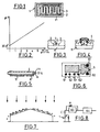
- the device consists of a reference sensor 1 as a whole and associated electronics 6.
- the senor 1 consists of an insulating support 11 whose outer face 111 exposed to the rain supports two metal electrodes in the form of combs 2 and 3. These two electrodes are nested one in the other, the lines of these electrodes being respectively alternated.
- the comb lines are close enough to detect a small drop or fog. As an indication, a spacing of about 0.25 mm between the electrodes 2 and 3 is a good compromise.
- the insulating support 11 is made of ceramic, for example of alumina (A1 2 0 3 at 96%).
- the electrodes 2 and 3 are produced by screen printing, for example according to the technology of thick layers.
- the sensor could be produced using hard or flexible printed circuit technology, the support being of the epoxy, polyamide, mylar type.
- the support could be constituted by the glass of the windshield, the electrodes being directly deposited on the glass of the windshield crossed by conductors.
- the face 111 of the support 11 is covered by a thin dielectric layer 4 of waterproof material having dielectric properties and preferably non-wetting.
- This layer completely covers, continuously, the electrodes 2 and 3 and the support 11. It transforms the sensor into a capacitor whose armatures are materialized by the two combs.
- This layer has a thickness between 5 and 100 f, .lm.
- the dielectric constant of the material should be less than the dielectric constant of water. In general, a dielectric constant less than or equal to 10 is sufficient.
- the diélec layer trique makes it possible to reduce, or even make almost linear, the non-linearities usually attributed to this type of sensor.
- a thickness of 20 ⁇ m of glass makes it possible to satisfy the detection of droplets and of mist.
- the material constituting the dielectric layer 4 belongs to the group glass, nylon, teflon, parylene.
- the electrodes 2 and 3 are connected to an associated electronic circuit 6 which translates the variations in capacity into variations in the period.
- connection between the electrodes 2 and 3 and the electronics 6 are made by connecting conductors which pass through the support in holes 13, 14 piercing the support right through.
- the holes are covered by layer 4.
- the sensor is thus completely isolated by layer 4.
- the sensor capacity is included in an RC type oscillator 63.
- the frequency supplied by this oscillator is divided by a frequency divider logic circuit 64 so that the signal is transported to a processing card.
- the divided frequency signal is sent to a circuit (eg PLL phase locked loop), measuring the positive variations of the signal period.
- An increase in the period corresponds to an increase in the capacity of the sensor, therefore to a supply of water to the glass.
- a heating circuit 5 is mounted under the support 11. This heating circuit is supplied by studs 51 and 52. It includes a thermistor with a positive temperature coefficient.
- the thermistor has a thermal transition point at the desired temperature.
- the thermistor is screen printed or deposited on the support 11 and it is associated with an electronic circuit keeping it at constant temperature.
- the associated electronic circuit 6 and the heating circuit 5 are arranged on the back of the insulating support 11 on the side protected from the rain.
- a first mode of mounting the sensor 1 consists in mounting it with an inclination very close to the windshield, if possible on the driver's side.
- the senor in a second embodiment, illustrated in FIG. 7, the sensor consists of two planar and inclined half-sensors each provided with electrodes and a dielectric layer.
- This roof arrangement promotes the flow of water on each side of the sensor.
- This solution could be useful in the case of rain coming from only one side of the vehicle, one of the planes remaining sensitive to rain. Due to the inclined position of the capture surface and the speed of the vehicle, the sensor in normal rain can never be in saturation. In the case of very heavy rain saturating the sensor, the abnormally high capacity, therefore easily detectable, makes it possible to automatically activate the rapid timing of the wipers.
- the electronic circuit supplies at the output of the oscillator a signal whose period is directly proportional to the capacity, that is to say to the presence of water on the sensor and the variation of period to the size of the drops.
- the signal frequency is divided to allow the signal to be transported to the processing board.
- the variation in capacity depends on the size of the drop and its impact on the protective layer 4. We can thus distinguish the different kinds of rain and automatically correct, by the impact crushing the drop on the glass, the variations due to the vehicle speed and rain intensity.
- the heating circuit located on the back of the sensor puts this sensor at a temperature at least equal to that of the windshield. It simulates the internal temperature of the passenger compartment directly influencing the windshield. It simulates the passage of the windscreen wipers evacuating rain on the windshield by a thermal evacuation of the drops on the sensor. It allows, in the case of fine rain or fog, to evacuate the water on the sensor and to have a good sensitivity to these fine droplets. It allows, in the case of snow, to defrost the sensor and to be sensitive to snowflakes turning into water on contact with the sensor.
Landscapes
- Engineering & Computer Science (AREA)
- Automation & Control Theory (AREA)
- Mechanical Engineering (AREA)
- Investigating Or Analyzing Materials By The Use Of Electric Means (AREA)
Claims (5)
Applications Claiming Priority (2)
| Application Number | Priority Date | Filing Date | Title |
|---|---|---|---|
| FR8803518 | 1988-03-18 | ||
| FR8803518A FR2628840B1 (fr) | 1988-03-18 | 1988-03-18 | Dispositif electronique de detection de pluie |
Publications (2)
| Publication Number | Publication Date |
|---|---|
| EP0333564A1 EP0333564A1 (de) | 1989-09-20 |
| EP0333564B1 true EP0333564B1 (de) | 1992-07-08 |
Family
ID=9364385
Family Applications (1)
| Application Number | Title | Priority Date | Filing Date |
|---|---|---|---|
| EP19890400668 Expired - Lifetime EP0333564B1 (de) | 1988-03-18 | 1989-03-10 | Elektronische Regen-Erkennungsvorrichtung |
Country Status (3)
| Country | Link |
|---|---|
| EP (1) | EP0333564B1 (de) |
| DE (1) | DE68901989T2 (de) |
| FR (1) | FR2628840B1 (de) |
Families Citing this family (8)
| Publication number | Priority date | Publication date | Assignee | Title |
|---|---|---|---|---|
| US4965698A (en) * | 1989-09-27 | 1990-10-23 | Johnson Service Company | Capacitance humidity sensor |
| DE4000736A1 (de) * | 1990-01-12 | 1991-07-18 | Vdo Schindling | Verfahren und anordnung zur steuerung eines scheibenwischers |
| DE19536621C2 (de) * | 1995-09-30 | 2000-11-23 | Bayerische Motoren Werke Ag | Vorrichtung zur elektronischen Steuerung eines Scheibenwischers bei Kraftfahrzeugen |
| US6612677B2 (en) * | 2001-07-25 | 2003-09-02 | Hewlett-Packard Company | Ink drop sensor |
| JP2007533961A (ja) | 2003-09-19 | 2007-11-22 | 滕▲しん▼ ▲孫▼ | 自動車ウィンドシールドガラスの環境変化を検知する装置と方法 |
| DE10348357A1 (de) * | 2003-10-17 | 2005-05-19 | Volkswagen Ag | Vorrichtung und Verfahren zum Steuern einer Scheibenwischeranlage eines Kraftfahrzeugs |
| CN108333644A (zh) * | 2018-03-12 | 2018-07-27 | 四平市吉华高新技术有限公司 | 一种雨量传感器元件及其制作方法和一种雨量传感器 |
| DE102020205401A1 (de) * | 2020-04-29 | 2021-11-04 | Robert Bosch Gesellschaft mit beschränkter Haftung | Regenerkennungsvorrichtung, Gartengerät mit der Regenerkennungsvorrichtung und Verfahren zu einer Erfassung von Regentropfen auf einer Oberfläche mittels einer Regenerkennungsvorrichtung |
Family Cites Families (6)
| Publication number | Priority date | Publication date | Assignee | Title |
|---|---|---|---|---|
| DE2010970A1 (de) * | 1970-03-09 | 1971-09-30 | Steger, Robert, 7030 Boblingen | Elektronisch gesteuerter Feuchtigkeits automat zum selbsttätigen Em und Aus schalten von elektrischen Scheibenwisch anlagen |
| FR2279303A1 (fr) * | 1974-06-28 | 1976-02-13 | Uralsky Politekhn Inst | Structure multicouche et procede de formation de jonctions intercouches dans ladite structure |
| DE2610896C3 (de) * | 1976-03-16 | 1979-02-22 | Guenther 3151 Eddesse Grassmann | Sensor zur Steuerung eines Scheibenwischermotors |
| US4317073A (en) * | 1977-02-03 | 1982-02-23 | Henry Blaszkowski | Windshield wiper control system |
| JPS59137842A (ja) * | 1983-01-28 | 1984-08-08 | Jidosha Denki Kogyo Co Ltd | 雨滴検出器の振動板保持構造 |
| EP0191639A3 (de) * | 1985-02-15 | 1989-07-12 | Toyota Jidosha Kabushiki Kaisha | Anlage und Verfahren zum Steuern eines Wischers |
-
1988
- 1988-03-18 FR FR8803518A patent/FR2628840B1/fr not_active Expired - Fee Related
-
1989
- 1989-03-10 EP EP19890400668 patent/EP0333564B1/de not_active Expired - Lifetime
- 1989-03-10 DE DE1989601989 patent/DE68901989T2/de not_active Expired - Fee Related
Also Published As
| Publication number | Publication date |
|---|---|
| EP0333564A1 (de) | 1989-09-20 |
| DE68901989T2 (de) | 1993-03-25 |
| FR2628840A1 (fr) | 1989-09-22 |
| FR2628840B1 (fr) | 1995-01-27 |
| DE68901989D1 (de) | 1992-08-13 |
Similar Documents
| Publication | Publication Date | Title |
|---|---|---|
| US4805070A (en) | Capacitive coupled moisture sensor | |
| CA2509975C (en) | Moisture detection system and method of use thereof | |
| EP0333564B1 (de) | Elektronische Regen-Erkennungsvorrichtung | |
| US4210021A (en) | Method and device for detecting icing of objects found in air flow | |
| US20050115308A1 (en) | Windshield moisture detector | |
| EP0762359B1 (de) | Verfahren und Vorrichtung zur Messung des Zustands einer Strassenoberfläche | |
| US5484121A (en) | Icing detector for aircraft surfaces | |
| US5821501A (en) | Heated mirror | |
| KR100367193B1 (ko) | 윈도우서리제거장치를자동작동시키기위한장치및방법 | |
| EP1396425A1 (de) | Eisdetektor für ein breites Spektrum von Vereisungsbedingungen | |
| FR2721107A1 (fr) | Dispositif de jaugeage de carburant. | |
| US7156552B2 (en) | Temperature sensor system for mobile platforms | |
| WO2008021809A2 (en) | Multi-layer windshield moisture detector | |
| EP0563174A1 (de) | Eisdetektor | |
| US3118063A (en) | Horizon sensors selectively responsive to a gaseous atmospheric component | |
| US20090033502A1 (en) | Aircraft icing sensor | |
| EP0485312B1 (de) | Verfahren zur Herstellung einer übertragbaren Zusammensetzung von einer elektronischen Schaltung für das Lesen und/oder den Betrieb und von einem Leitungsfähigen (oder nicht-)Träger | |
| EP0323937B1 (de) | Trägerstruktur für Gassensoren | |
| EP0458691A1 (de) | Verbesserung für thermische Druckknöpfe | |
| EP1902600B1 (de) | Verbesserte bestückte leiterplatte mit der fähigkeit zur erkennung unbeabsichtigter erhitzung | |
| JPH02503953A (ja) | 氷検出プローブ | |
| CA1310692C (en) | Capacitive coupled moisture sensor | |
| FR2782159A1 (fr) | Dispositif de detection d'atteinte a l'integrite d'une paroi | |
| FR3100419A1 (fr) | vitrage à chauffage électrique avec capteur d’état de surface capacitif | |
| WO2025257191A1 (fr) | Sonde de mesure aérodynamique |
Legal Events
| Date | Code | Title | Description |
|---|---|---|---|
| PUAI | Public reference made under article 153(3) epc to a published international application that has entered the european phase |
Free format text: ORIGINAL CODE: 0009012 |
|
| 17P | Request for examination filed |
Effective date: 19890315 |
|
| AK | Designated contracting states |
Kind code of ref document: A1 Designated state(s): DE ES GB IT |
|
| 17Q | First examination report despatched |
Effective date: 19901220 |
|
| GRAA | (expected) grant |
Free format text: ORIGINAL CODE: 0009210 |
|
| AK | Designated contracting states |
Kind code of ref document: B1 Designated state(s): DE ES GB IT |
|
| PG25 | Lapsed in a contracting state [announced via postgrant information from national office to epo] |
Ref country code: IT Free format text: LAPSE BECAUSE OF FAILURE TO SUBMIT A TRANSLATION OF THE DESCRIPTION OR TO PAY THE FEE WITHIN THE PRE;WARNING: LAPSES OF ITALIAN PATENTS WITH EFFECTIVE DATE BEFORE 2007 MAY HAVE OCCURRED AT ANY TIME BEFORE 2007. THE CORRECT EFFECTIVE DATE MAY BE DIFFERENT FROM THE ONE RECORDED.SCRIBED TIME-LIMIT Effective date: 19920708 Ref country code: ES Free format text: THE PATENT HAS BEEN ANNULLED BY A DECISION OF A NATIONAL AUTHORITY Effective date: 19920708 |
|
| REF | Corresponds to: |
Ref document number: 68901989 Country of ref document: DE Date of ref document: 19920813 |
|
| GBT | Gb: translation of ep patent filed (gb section 77(6)(a)/1977) | ||
| PLBE | No opposition filed within time limit |
Free format text: ORIGINAL CODE: 0009261 |
|
| STAA | Information on the status of an ep patent application or granted ep patent |
Free format text: STATUS: NO OPPOSITION FILED WITHIN TIME LIMIT |
|
| 26N | No opposition filed | ||
| PGFP | Annual fee paid to national office [announced via postgrant information from national office to epo] |
Ref country code: DE Payment date: 19960528 Year of fee payment: 8 |
|
| PGFP | Annual fee paid to national office [announced via postgrant information from national office to epo] |
Ref country code: GB Payment date: 19960529 Year of fee payment: 8 |
|
| PG25 | Lapsed in a contracting state [announced via postgrant information from national office to epo] |
Ref country code: GB Effective date: 19970310 |
|
| GBPC | Gb: european patent ceased through non-payment of renewal fee |
Effective date: 19970310 |
|
| PG25 | Lapsed in a contracting state [announced via postgrant information from national office to epo] |
Ref country code: DE Effective date: 19971202 |