EP0333191B1 - Hydraulic pump, particularly for dishwashers or the like - Google Patents
Hydraulic pump, particularly for dishwashers or the like Download PDFInfo
- Publication number
- EP0333191B1 EP0333191B1 EP89104730A EP89104730A EP0333191B1 EP 0333191 B1 EP0333191 B1 EP 0333191B1 EP 89104730 A EP89104730 A EP 89104730A EP 89104730 A EP89104730 A EP 89104730A EP 0333191 B1 EP0333191 B1 EP 0333191B1
- Authority
- EP
- European Patent Office
- Prior art keywords
- impeller
- inlet
- movable element
- hydraulic pump
- diffusion chamber
- Prior art date
- Legal status (The legal status is an assumption and is not a legal conclusion. Google has not performed a legal analysis and makes no representation as to the accuracy of the status listed.)
- Expired - Lifetime
Links
- 238000009792 diffusion process Methods 0.000 claims description 31
- 239000007788 liquid Substances 0.000 description 6
- 238000005406 washing Methods 0.000 description 5
- 238000004851 dishwashing Methods 0.000 description 2
- 238000005293 physical law Methods 0.000 description 1
- 230000001105 regulatory effect Effects 0.000 description 1
Images
Classifications
-
- F—MECHANICAL ENGINEERING; LIGHTING; HEATING; WEAPONS; BLASTING
- F04—POSITIVE - DISPLACEMENT MACHINES FOR LIQUIDS; PUMPS FOR LIQUIDS OR ELASTIC FLUIDS
- F04D—NON-POSITIVE-DISPLACEMENT PUMPS
- F04D29/00—Details, component parts, or accessories
- F04D29/40—Casings; Connections of working fluid
- F04D29/42—Casings; Connections of working fluid for radial or helico-centrifugal pumps
- F04D29/44—Fluid-guiding means, e.g. diffusers
- F04D29/46—Fluid-guiding means, e.g. diffusers adjustable
- F04D29/466—Fluid-guiding means, e.g. diffusers adjustable especially adapted for liquid fluid pumps
-
- A—HUMAN NECESSITIES
- A47—FURNITURE; DOMESTIC ARTICLES OR APPLIANCES; COFFEE MILLS; SPICE MILLS; SUCTION CLEANERS IN GENERAL
- A47L—DOMESTIC WASHING OR CLEANING; SUCTION CLEANERS IN GENERAL
- A47L15/00—Washing or rinsing machines for crockery or tableware
- A47L15/42—Details
- A47L15/4214—Water supply, recirculation or discharge arrangements; Devices therefor
- A47L15/4225—Arrangements or adaption of recirculation or discharge pumps
Definitions
- the present invention relates to a hydraulic pump, particularly for dishwashers or the like.
- a first type of hydraulic pump which is constituted by a casing which accommodates an impeller and defines, around said impeller, a diffusion chamber with a passage cross section which increases in the direction of the liquid propelled by the impeller.
- the diffusion chamber is connected in output, i.e. at its greater passage cross section, to a first delivery duct which feeds the sprinkler of the lower dish-holder.
- a second delivery duct extends from said first duct after the pump and feeds the sprinkler of the upper dish-holder.
- a second type of hydraulic pump is also known; said pump is constituted by a casing which accommodates an impeller and defines, about said impeller, a diffusion chamber which is connected to two delivery ducts having angularily spaced inlets with respect to the axis of the impeller; said delivery ducts respectively feed the sprinkler of the lower dish-holder and the sprinkler of the upper dish-holder.
- the diffusion chamber is practically divided into two chambers, the passage cross sections whereof increase in the direction of the liquid propelled by the impeller towards the related inlet of one of the delivery ducts.
- the pump can be assimilated to two pumps which have an equal head and a capacity which is proportional to the arc of extension of the related diffusion chamber and separately feed the two delivery ducts.
- Some dishwashing machines which use pumps of the first type, can wash dishes contained in the lower dish-holder, for example in case of small loads.
- the upper sprinkler may be manually overturned so that the two sprinklers strike the dishes contained in the lower dish-holder with the pump's entire capacity.
- the flow-rate can be adjusted in one of the delivery ducts by acting manually on a valve arranged on a duct to be adjusted, generally on the delivery duct which feeds the upper sprinkler.
- a radial flow turbo-machine i.e. a centrifugal pump or fan, including a multipart wall, the relative positions of the parts of said multipart wall being adjustable radially as to enable the cross-sectional area of each flow passage to be varied and thereby to provide a control over flow through the volute chamber.
- the described system cannot allow to modify substantially the ratio between the two flows, but only to adjust the value of both, from a maximum to a minimum, may be zero.
- the aim of the present invention is to obviate the above described disadvantages by providing a hydraulic pump, in particular for dishwashers, which allows to feed one or both of the delivery ducts automatically according to the requirements.
- an object of the invention is to provide a hydraulic pump which allows to automatically adjust the flow-rate on the two delivery ducts fed by said pump and/or of the head on only one of said ducts .
- Another object of the invention is to provide a pump which fully meets the various requirements of the preset washing cycles.
- Still another object of the invention is to provide a pump which reduces consumption and noise, particularly in the cycles which require low hydraulic power, such as for example during rinsing or in so-called economy cycles.
- Not least object of the invention is to provide a pump in which the various possible adjustments can be controlled by an automatic programming element.
- a hydraulic pump particularly for dishwashers or the like, comprising a casing which rotatably accommodates an impeller and defines, peripherally to said impeller, a diffusion chamber which has a first inlet for a first delivery duct and a second inlet for a second delivery duct, said two inlets being located on approximately diametrically opposite positions, and wherein, proximate to at least the second one of said inlets, adjustment means are provided in said diffusion chamber, and can be controllably actuated to vary the degree of opening of said second one of said inlets, characterised in that said adjustment means comprise a movable element, which, in a first position, divides said diffusion chamber into two partial diffusion chambers, hydraulically substantially independent from one another, each of said partial diffusion chambers being connected to one of said inlets, and, in a second position, closes said second inlet realising only one diffusion chamber, which connects to said first inlet.
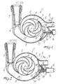
- the pump according to the invention comprises a casing 2 which, like known pumps, rotatably accommodates an impeller 3 with vanes 4.
- the casing 2 defines a diffusion chamber 5 around the impeller 3; said chamber has a first inlet 6, to be connected for example to a first delivery duct 7 which feeds the lower sprinkler of a dishwasher, and a second inlet 8, to be connected for example to a second delivery duct 9 which feeds the upper sprinkler.
- the diffusion chamber 5 is shaped so that its passage cross section increases concordantly with the direction of the liquid propelled through said chamber by the impeller 3.
- the first inlet 6 is arranged in output to the diffusion chamber 5, i.e. at the greater passage cross section of said chamber, while the second inlet 8 is arranged ahead of the first inlet 6 with respect to the direction of flow of the liquid propelled by the impeller 3.
- adjustment means 10 are provided proximate to the second inlet 8 in the diffusion chamber 5 and can be controllably actuated to vary the degree of opening of the second inlet 8.
- the adjustment means 10 are constituted by a movable element 11 in the shape of a vane which is concave on the side directed toward the impeller 3 and can be controllably moved from an opening position, in which it keeps the second inlet 8 open, to a closure position, in which it completely closes said inlet 8, with the possibility of intermediate positions.
- One of the ends of the vane 11 is pivoted to the casing 2 proximate to the wall thereof which radially delimits the diffusion chamber 5, while the opposite end extends proximate to the second inlet 8.
- the vane 11 can oscillate controllably about an axis 12 which is parallel to the axis 23 of the impeller 3 to pass from the opening position to the closure position or vice versa.
- the impeller 11 has, on its side directed toward the impeller 3, a curved profile which is connected to the inner surface of the casing, which radially delimits the diffusion chamber 5, when said vane is in its closure position and connects to the perimeter of the impeller 3 when the vane is in its opening position.
- the vane 11 Proximate to its free end, on its side directed oppositely to the impeller, the vane 11 has a first portion 11a which connects to the perimeter of the impeller in its opening position and a second portion 11b which is concave on its side directed towards the inlet 8 and connects the first portion 11a to the inlet 8.
- a cavity 13 is advantageously defined on the wall of the casing which radially delimits the diffusion chamber 5; said cavity is adapted to partially accommodate the vane 11 in its closure position.
- the vane 11 has its free end close to the impeller in its opening position and divides the diffusion chamber 5 into two hydraulically independent partial diffusion chambers; each chamber is connected to one of the inlets 6 and 8 and its passage cross section increases towards the related inlet.
- actuation means 15 can be used which act on the pivoting pin 14 of the vane 11 or directly on the vane 11.
- said actuation means are advantageously constituted by a known linear motor 16 which is associated with the casing 2 proximate to the cavity 13 and has a control rod 17 pivoted with its free end to the vane 11. More particularly, the free end of the actuation rod 17 is pivoted in a slot 18 defined in the vane 11.
- Elastic means 19 are furthermore provided between the vane 11 and the casing 2; said means are constituted for example by a spring and elastically bias the action of the linear motor 16.
- the impeller 3 may be advantageously actuated by an electric motor of a known type, not illustrated, having a controllably variable rpm rate.
- the vane 11 is moved to its closure position so as to close the second inlet 8 (figure 2 ). In this manner the pump's entire capacity is conveyed to the lower sprinkler.
- the rotation rate of the motor which actuates the impeller 3 can be reduced according to the various requirements, keeping the vane 11 respectively in its opening position or in its closure position.
- a further variation of the flow-rate and/or the head on the two ducts 7 and 9, according to the requirements, can be obtained by appropriately arranging the vane 11 in an intermediate position between its opening position and its closure position.
- the pump according to the invention fully achieves the intended aim, since it allows to automatically adjust the flow-rate and/or the head on the two delivery ducts or on a single duct so as to fully meet the most disparate washing requirements of a dishwasher, and furthermore achieves greater washing efficiency and a reduction in costs. With such adjustments it is furthermore possible to adapt the pump's hydraulic characteristics even to operating conditions which require reduced flow-rates, thus avoiding noise.
Landscapes
- Engineering & Computer Science (AREA)
- Mechanical Engineering (AREA)
- General Engineering & Computer Science (AREA)
- Water Supply & Treatment (AREA)
- Structures Of Non-Positive Displacement Pumps (AREA)
- Details Of Reciprocating Pumps (AREA)
Description
- The present invention relates to a hydraulic pump, particularly for dishwashers or the like.
- As is known, in dishwashing machines it is necessary to use the same pump to feed the delivery conduits of two or more separate hydraulic circuits, such as for example the circuit of the sprinkler of the upper dish-holder and that of the lower dish-holder. A first type of hydraulic pump is known which is constituted by a casing which accommodates an impeller and defines, around said impeller, a diffusion chamber with a passage cross section which increases in the direction of the liquid propelled by the impeller. The diffusion chamber is connected in output, i.e. at its greater passage cross section, to a first delivery duct which feeds the sprinkler of the lower dish-holder. A second delivery duct extends from said first duct after the pump and feeds the sprinkler of the upper dish-holder.
- A second type of hydraulic pump is also known; said pump is constituted by a casing which accommodates an impeller and defines, about said impeller, a diffusion chamber which is connected to two delivery ducts having angularily spaced inlets with respect to the axis of the impeller; said delivery ducts respectively feed the sprinkler of the lower dish-holder and the sprinkler of the upper dish-holder. The diffusion chamber is practically divided into two chambers, the passage cross sections whereof increase in the direction of the liquid propelled by the impeller towards the related inlet of one of the delivery ducts. In this case the pump can be assimilated to two pumps which have an equal head and a capacity which is proportional to the arc of extension of the related diffusion chamber and separately feed the two delivery ducts.
- Some dishwashing machines, which use pumps of the first type, can wash dishes contained in the lower dish-holder, for example in case of small loads. In such machines the upper sprinkler may be manually overturned so that the two sprinklers strike the dishes contained in the lower dish-holder with the pump's entire capacity.
- In other kinds of machine, the flow-rate can be adjusted in one of the delivery ducts by acting manually on a valve arranged on a duct to be adjusted, generally on the delivery duct which feeds the upper sprinkler.
- Such known types of machine, though they respectively allow to wash the dishes contained in a single dish-holder or to adjust the flow-rate along one of the delivery ducts, have the disadvantages of requiring a manual intervention on the part by the user and of not allowing a satisfactory adjustment of the flow-rate and/or of the head on the delivery ducts according to the actual requirements of the machine's washing cycles.
- From GB Patent No 1,379,075 it is known a radial flow turbo-machine, i.e. a centrifugal pump or fan, including a multipart wall, the relative positions of the parts of said multipart wall being adjustable radially as to enable the cross-sectional area of each flow passage to be varied and thereby to provide a control over flow through the volute chamber.
- The described system cannot allow to modify substantially the ratio between the two flows, but only to adjust the value of both, from a maximum to a minimum, may be zero.
- From Japan Patent application No 58-133407 it is known a multi-vane fan, where a movable damper plate is turnably fitted on the inside of the casing, allowing in a first position to close a first delivery port, in a second position to close a second delivery port, and, in an intermediate position, to increase the air flow through the second delivery port while additional air is sucked through the first delivery port, which is turned into a supply port.
- Fans however are machines that work on physical laws different of those regulating liquid pumps; in fact air (and gas in general) are well compressible, while liquids are incompressible; problems and behaviour are very different.
- The aim of the present invention is to obviate the above described disadvantages by providing a hydraulic pump, in particular for dishwashers, which allows to feed one or both of the delivery ducts automatically according to the requirements.
- Within the scope of this aim, an object of the invention is to provide a hydraulic pump which allows to automatically adjust the flow-rate on the two delivery ducts fed by said pump and/or of the head on only one of said ducts .
- Another object of the invention is to provide a pump which fully meets the various requirements of the preset washing cycles.
- Still another object of the invention is to provide a pump which reduces consumption and noise, particularly in the cycles which require low hydraulic power, such as for example during rinsing or in so-called economy cycles.
- Not least object of the invention is to provide a pump in which the various possible adjustments can be controlled by an automatic programming element.
- This aim, as well as these and other objects which will become apparent hereinafter, are achieved by a hydraulic pump, particularly for dishwashers or the like, comprising a casing which rotatably accommodates an impeller and defines, peripherally to said impeller, a diffusion chamber which has a first inlet for a first delivery duct and a second inlet for a second delivery duct, said two inlets being located on approximately diametrically opposite positions, and wherein, proximate to at least the second one of said inlets, adjustment means are provided in said diffusion chamber, and can be controllably actuated to vary the degree of opening of said second one of said inlets, characterised in that said adjustment means comprise a movable element, which, in a first position, divides said diffusion chamber into two partial diffusion chambers, hydraulically substantially independent from one another, each of said partial diffusion chambers being connected to one of said inlets, and, in a second position, closes said second inlet realising only one diffusion chamber, which connects to said first inlet.
- Further characteristics and advantages of the invention will become apparent from the description of a preferred but not exclusive embodiment of the pump according to the invention, illustrated only by way of non-limiting example in the accompanying drawings, wherein:
- figure 1 is a schematic sectional view of the pump according to the invention, taken along a plane which is perpendicular to the axis of the impeller, in an operating condition; and
- figure 2 is a schematic sectional view of the pump according to the invention, similar to figure 1, in another operating condition.
- With reference to the above described figures, the pump according to the invention, generally indicated by the reference numeral 1, comprises a casing 2 which, like known pumps, rotatably accommodates an
impeller 3 withvanes 4. The casing 2 defines adiffusion chamber 5 around theimpeller 3; said chamber has afirst inlet 6, to be connected for example to afirst delivery duct 7 which feeds the lower sprinkler of a dishwasher, and asecond inlet 8, to be connected for example to asecond delivery duct 9 which feeds the upper sprinkler. Thediffusion chamber 5 is shaped so that its passage cross section increases concordantly with the direction of the liquid propelled through said chamber by theimpeller 3. - The
first inlet 6 is arranged in output to thediffusion chamber 5, i.e. at the greater passage cross section of said chamber, while thesecond inlet 8 is arranged ahead of thefirst inlet 6 with respect to the direction of flow of the liquid propelled by theimpeller 3. - According to the invention, adjustment means 10 are provided proximate to the
second inlet 8 in thediffusion chamber 5 and can be controllably actuated to vary the degree of opening of thesecond inlet 8. - More particularly, the adjustment means 10 are constituted by a
movable element 11 in the shape of a vane which is concave on the side directed toward theimpeller 3 and can be controllably moved from an opening position, in which it keeps thesecond inlet 8 open, to a closure position, in which it completely closes saidinlet 8, with the possibility of intermediate positions. - One of the ends of the
vane 11 is pivoted to the casing 2 proximate to the wall thereof which radially delimits thediffusion chamber 5, while the opposite end extends proximate to thesecond inlet 8. Thevane 11 can oscillate controllably about anaxis 12 which is parallel to theaxis 23 of theimpeller 3 to pass from the opening position to the closure position or vice versa. - The
impeller 11 has, on its side directed toward theimpeller 3, a curved profile which is connected to the inner surface of the casing, which radially delimits thediffusion chamber 5, when said vane is in its closure position and connects to the perimeter of theimpeller 3 when the vane is in its opening position. - Proximate to its free end, on its side directed oppositely to the impeller, the
vane 11 has afirst portion 11a which connects to the perimeter of the impeller in its opening position and asecond portion 11b which is concave on its side directed towards theinlet 8 and connects thefirst portion 11a to theinlet 8. - A
cavity 13 is advantageously defined on the wall of the casing which radially delimits thediffusion chamber 5; said cavity is adapted to partially accommodate thevane 11 in its closure position. - In this manner, by virtue of its configuration and of the
cavity 13, thevane 11 has its free end close to the impeller in its opening position and divides thediffusion chamber 5 into two hydraulically independent partial diffusion chambers; each chamber is connected to one of theinlets - In order to move the
vane 11 from its opening position to its closure position, or to an intermediate position, actuation means 15 can be used which act on the pivotingpin 14 of thevane 11 or directly on thevane 11. In the illustrated embodiment said actuation means are advantageously constituted by a knownlinear motor 16 which is associated with the casing 2 proximate to thecavity 13 and has acontrol rod 17 pivoted with its free end to thevane 11. More particularly, the free end of theactuation rod 17 is pivoted in aslot 18 defined in thevane 11.Elastic means 19 are furthermore provided between thevane 11 and the casing 2; said means are constituted for example by a spring and elastically bias the action of thelinear motor 16. - In order to vary the flow-rate and the head of the pump under invariant hydraulic conditions set by positioning the
vane 11, theimpeller 3 may be advantageously actuated by an electric motor of a known type, not illustrated, having a controllably variable rpm rate. - The operation of the pump according to the invention is as follows.
- If both the upper sprinkler and the lower sprinkler must be fed, the
vane 11 is moved to its open position (figure 1). In this manner the pump behaves like two independent pumps which separately feed the twodelivery ducts - If only the lower sprinkler is to be fed, the
vane 11 is moved to its closure position so as to close the second inlet 8 (figure 2 ). In this manner the pump's entire capacity is conveyed to the lower sprinkler.
During the steps of the washing cycle which require a reduced head and/or capacity both on thefirst delivery duct 7 and on thesecond delivery duct 9 or only on thesecond delivery duct 9, the rotation rate of the motor which actuates theimpeller 3 can be reduced according to the various requirements, keeping thevane 11 respectively in its opening position or in its closure position. - A further variation of the flow-rate and/or the head on the two
ducts vane 11 in an intermediate position between its opening position and its closure position. - In practice it has been observed that the pump according to the invention fully achieves the intended aim, since it allows to automatically adjust the flow-rate and/or the head on the two delivery ducts or on a single duct so as to fully meet the most disparate washing requirements of a dishwasher, and furthermore achieves greater washing efficiency and a reduction in costs. With such adjustments it is furthermore possible to adapt the pump's hydraulic characteristics even to operating conditions which require reduced flow-rates, thus avoiding noise.
Claims (10)
- Hydraulic pump, particularly for dishwashers or the like, comprising a casing (2) which rotatably accommodates an impeller (3) and defines, peripherally to said impeller, a diffusion chamber (5) which has a first inlet (6) for a first delivery duct (7) and a second inlet (8) for a second delivery duct (9), said two inlets being located on approximately diametrically opposite positions, and wherein, proximate to at least the second one (8) of said inlets, adjustment means are provided in said diffusion chamber, and can be controllably actuated to vary the degree of opening of said second one of said inlets, characterised in that said adjustment means comprise a movable element (11), which, in a first position (fig. 1), divides said diffusion chamber (5) into two partial diffusion chambers, hydraulically substantially independent from one another, each of said partial diffusion chambers being connected to one of said inlets, and, in a second position (fig. 2), closes said second inlet (8) realising only one diffusion chamber (5), which connects to said first inlet (6).
- Hydraulic pump, according to claim 1, characterised in that said movable element (11) is constituted by a vane which is concave on its side directed towards said impeller (3) and has one of its ends pivot to said casing (2), proximate to the wall which radially delimits said diffusion chamber (5), said vane being oscillable about an axis (12) which is parallel to the axis (23) of said impeller (3) to move its other end towards said impeller or away therefrom to close said second inlet (8).
- Hydraulic pump, according to one or more of the preceding claims, characterised in that said movable element (11) has, on its side directed towards said impeller (3), a curved profile which connects to the inner surface of said casing (2) which radially delimits said diffusion chamber (5) when said movable element is in said closure position and which connects to the perimeter of said impeller (3) when said movable element is in said opening position.
- Hydraulic pump, according to one or more of the preceding claims, characterised in that said movable element (11) has, on its side directed opposite to said impeller (3), a first portion (11a) which connects to the perimeter of said impeller (3) and a second concave portion (11b) which is directed towards said second inlet (8) and connects said first portion (11a) with said second inlet (8) when said movable element is in said opening position.
- Hydraulic pump, according to one or more of the preceding claims, characterised in that on the wall of said casing (2) which radially delimits said diffusion chamber (5), a cavity (13) is formed and is adapted to contain at least partially said movable element (11) in said closure position.
- Hydraulic pump, according to one or more of the preceding claims, characterised in that when said movable element (11) is in its closure position the cross section of said diffusion chamber (5) increases towards said first inlet (6), and when said movable element is in its opening position the cross section of said diffusion chamber (5) increases towards said second inlet (8) and increases from said movable element towards said first inlet (6).
- Hydraulic pump, according to one or more of the preceding claims, characterised in that said impeller (3) is actuated by a motor with a variable rpm rate.
- Hydraulic pump, according to one or more of the preceding claims, characterised in that it comprises actuation means (15) which act on said movable element (11) to vary the degree of opening of said second inlet (8).
- Hydraulic pump, according to claim 8, characterised in that said actuation means comprises a linear motor (16) which is supported by said casing (2) and has an actuation rod (17) pivoted to said movable element (11), said linear motor (16) being arranged with said movable actuation rod along a direction which has a radial component with respect to said impeller (3).
- Hydraulic pump, according to one or more of the preceding claims, characterised in that said movable element (11) can oscillate about said axis (12) which is parallel to the axis (23) of said impeller (3) in contrast with elastic means (19) or by virtue thereof.
Applications Claiming Priority (2)
| Application Number | Priority Date | Filing Date | Title |
|---|---|---|---|
| IT8819849A IT1216152B (en) | 1988-03-18 | 1988-03-18 | HYDRAULIC PUMP, PARTICULARLY FOR DISHWASHER OR SIMILAR. |
| IT1984988 | 1988-03-18 |
Publications (3)
| Publication Number | Publication Date |
|---|---|
| EP0333191A2 EP0333191A2 (en) | 1989-09-20 |
| EP0333191A3 EP0333191A3 (en) | 1990-07-18 |
| EP0333191B1 true EP0333191B1 (en) | 1993-07-14 |
Family
ID=11161789
Family Applications (1)
| Application Number | Title | Priority Date | Filing Date |
|---|---|---|---|
| EP89104730A Expired - Lifetime EP0333191B1 (en) | 1988-03-18 | 1989-03-16 | Hydraulic pump, particularly for dishwashers or the like |
Country Status (4)
| Country | Link |
|---|---|
| EP (1) | EP0333191B1 (en) |
| DE (1) | DE68907505T2 (en) |
| ES (1) | ES2043922T3 (en) |
| IT (1) | IT1216152B (en) |
Families Citing this family (4)
| Publication number | Priority date | Publication date | Assignee | Title |
|---|---|---|---|---|
| TWI356822B (en) | 2001-08-13 | 2012-01-21 | Du Pont | Novel substituted dihydro 3-halo-1h-pyrazole-5-car |
| GB0808595D0 (en) * | 2008-05-13 | 2008-06-18 | Interpet Ltd | Anti-blockage pump |
| CN108496011B (en) * | 2016-01-22 | 2021-04-13 | 利滕斯汽车合伙公司 | Pump with variable flow diverter forming volute |
| CN111765124A (en) * | 2020-06-23 | 2020-10-13 | 西安航空学院 | Angle-adjustable volute tongue assembly and fuel centrifugal pump |
Family Cites Families (2)
| Publication number | Priority date | Publication date | Assignee | Title |
|---|---|---|---|---|
| DE2208622A1 (en) * | 1972-02-24 | 1973-09-06 | Bosch Hausgeraete Gmbh | DISHWASHER WITH A CIRCULAR PUMP |
| GB1379075A (en) * | 1973-01-16 | 1975-01-02 | Lanyon T B | Radial flow turbo-machines |
-
1988
- 1988-03-18 IT IT8819849A patent/IT1216152B/en active
-
1989
- 1989-03-16 DE DE89104730T patent/DE68907505T2/en not_active Expired - Lifetime
- 1989-03-16 EP EP89104730A patent/EP0333191B1/en not_active Expired - Lifetime
- 1989-03-16 ES ES89104730T patent/ES2043922T3/en not_active Expired - Lifetime
Also Published As
| Publication number | Publication date |
|---|---|
| DE68907505T2 (en) | 1994-01-05 |
| EP0333191A3 (en) | 1990-07-18 |
| EP0333191A2 (en) | 1989-09-20 |
| IT1216152B (en) | 1990-02-22 |
| DE68907505D1 (en) | 1993-08-19 |
| ES2043922T3 (en) | 1994-01-01 |
| IT8819849A0 (en) | 1988-03-18 |
Similar Documents
| Publication | Publication Date | Title |
|---|---|---|
| US4802817A (en) | Centrifugal pump with self-regulating impeller discharge shutter | |
| US4890980A (en) | Centrifugal pump | |
| US7100623B2 (en) | Dishwasher having spray arms and a circulation pump | |
| DK169390B1 (en) | radial fan | |
| US3726308A (en) | Suction check valve for pumps | |
| CN104963894A (en) | Volute type centrifugal fan with one let and two outlets | |
| JPS5947160B2 (en) | variable performance pump | |
| EP1403521B1 (en) | Pump having one inlet and two outlets | |
| US2810345A (en) | Pump device | |
| EP0333191A2 (en) | Hydraulic pump, particularly for dishwashers or the like | |
| JPS54131104A (en) | Centrifugal compressor | |
| US2817475A (en) | Centrifugal compressor and method of controlling the same | |
| CN115444343B (en) | An assembly structure of an open water pump and a cleaning machine | |
| US4177018A (en) | Apparatus for regulating the passage and flow-rate of a liquid | |
| CN221401072U (en) | Open water pump for cleaning machine and cleaning machine | |
| US3289597A (en) | Centrifugal pump | |
| CN119769966B (en) | Cleaning machine and cleaning method | |
| CN222018269U (en) | Cleaning machine | |
| KR100457594B1 (en) | Dish washer | |
| EP3449796A1 (en) | Washing pump and dishwasher including the same | |
| CN222502186U (en) | Water pump for cleaning machine and cleaning machine | |
| CN113167256B (en) | Fluid pump | |
| US6743000B2 (en) | Hydraulic pump with flow guider | |
| WO2004020340A3 (en) | Fluid treatment system | |
| KR910003546Y1 (en) | Fluid flow control apparatus for centrifugal pump |
Legal Events
| Date | Code | Title | Description |
|---|---|---|---|
| PUAI | Public reference made under article 153(3) epc to a published international application that has entered the european phase |
Free format text: ORIGINAL CODE: 0009012 |
|
| AK | Designated contracting states |
Kind code of ref document: A2 Designated state(s): DE ES FR GB |
|
| PUAL | Search report despatched |
Free format text: ORIGINAL CODE: 0009013 |
|
| AK | Designated contracting states |
Kind code of ref document: A3 Designated state(s): DE ES FR GB |
|
| 17P | Request for examination filed |
Effective date: 19900829 |
|
| 17Q | First examination report despatched |
Effective date: 19910828 |
|
| GRAA | (expected) grant |
Free format text: ORIGINAL CODE: 0009210 |
|
| AK | Designated contracting states |
Kind code of ref document: B1 Designated state(s): DE ES FR GB |
|
| REF | Corresponds to: |
Ref document number: 68907505 Country of ref document: DE Date of ref document: 19930819 |
|
| ET | Fr: translation filed | ||
| REG | Reference to a national code |
Ref country code: ES Ref legal event code: FG2A Ref document number: 2043922 Country of ref document: ES Kind code of ref document: T3 |
|
| PLBE | No opposition filed within time limit |
Free format text: ORIGINAL CODE: 0009261 |
|
| STAA | Information on the status of an ep patent application or granted ep patent |
Free format text: STATUS: NO OPPOSITION FILED WITHIN TIME LIMIT |
|
| 26N | No opposition filed | ||
| REG | Reference to a national code |
Ref country code: GB Ref legal event code: IF02 |
|
| PGFP | Annual fee paid to national office [announced via postgrant information from national office to epo] |
Ref country code: ES Payment date: 20080328 Year of fee payment: 20 |
|
| PGFP | Annual fee paid to national office [announced via postgrant information from national office to epo] |
Ref country code: GB Payment date: 20080326 Year of fee payment: 20 |
|
| PGFP | Annual fee paid to national office [announced via postgrant information from national office to epo] |
Ref country code: DE Payment date: 20080415 Year of fee payment: 20 |
|
| PGFP | Annual fee paid to national office [announced via postgrant information from national office to epo] |
Ref country code: FR Payment date: 20080319 Year of fee payment: 20 |
|
| REG | Reference to a national code |
Ref country code: GB Ref legal event code: PE20 Expiry date: 20090315 |
|
| REG | Reference to a national code |
Ref country code: ES Ref legal event code: FD2A Effective date: 20090317 |
|
| PG25 | Lapsed in a contracting state [announced via postgrant information from national office to epo] |
Ref country code: GB Free format text: LAPSE BECAUSE OF EXPIRATION OF PROTECTION Effective date: 20090315 |
|
| PG25 | Lapsed in a contracting state [announced via postgrant information from national office to epo] |
Ref country code: ES Free format text: LAPSE BECAUSE OF EXPIRATION OF PROTECTION Effective date: 20090317 |