EP0333015A2 - Flow-control valve - Google Patents
Flow-control valve Download PDFInfo
- Publication number
- EP0333015A2 EP0333015A2 EP89104104A EP89104104A EP0333015A2 EP 0333015 A2 EP0333015 A2 EP 0333015A2 EP 89104104 A EP89104104 A EP 89104104A EP 89104104 A EP89104104 A EP 89104104A EP 0333015 A2 EP0333015 A2 EP 0333015A2
- Authority
- EP
- European Patent Office
- Prior art keywords
- control valve
- rotatable
- flow
- seal member
- defining
- Prior art date
- Legal status (The legal status is an assumption and is not a legal conclusion. Google has not performed a legal analysis and makes no representation as to the accuracy of the status listed.)
- Withdrawn
Links
Images

Classifications
-
- F—MECHANICAL ENGINEERING; LIGHTING; HEATING; WEAPONS; BLASTING
- F16—ENGINEERING ELEMENTS AND UNITS; GENERAL MEASURES FOR PRODUCING AND MAINTAINING EFFECTIVE FUNCTIONING OF MACHINES OR INSTALLATIONS; THERMAL INSULATION IN GENERAL
- F16K—VALVES; TAPS; COCKS; ACTUATING-FLOATS; DEVICES FOR VENTING OR AERATING
- F16K3/00—Gate valves or sliding valves, i.e. cut-off apparatus with closing members having a sliding movement along the seat for opening and closing
- F16K3/22—Gate valves or sliding valves, i.e. cut-off apparatus with closing members having a sliding movement along the seat for opening and closing with sealing faces shaped as surfaces of solids of revolution
- F16K3/24—Gate valves or sliding valves, i.e. cut-off apparatus with closing members having a sliding movement along the seat for opening and closing with sealing faces shaped as surfaces of solids of revolution with cylindrical valve members
-
- F—MECHANICAL ENGINEERING; LIGHTING; HEATING; WEAPONS; BLASTING
- F16—ENGINEERING ELEMENTS AND UNITS; GENERAL MEASURES FOR PRODUCING AND MAINTAINING EFFECTIVE FUNCTIONING OF MACHINES OR INSTALLATIONS; THERMAL INSULATION IN GENERAL
- F16K—VALVES; TAPS; COCKS; ACTUATING-FLOATS; DEVICES FOR VENTING OR AERATING
- F16K3/00—Gate valves or sliding valves, i.e. cut-off apparatus with closing members having a sliding movement along the seat for opening and closing
- F16K3/02—Gate valves or sliding valves, i.e. cut-off apparatus with closing members having a sliding movement along the seat for opening and closing with flat sealing faces; Packings therefor
- F16K3/04—Gate valves or sliding valves, i.e. cut-off apparatus with closing members having a sliding movement along the seat for opening and closing with flat sealing faces; Packings therefor with pivoted closure members
- F16K3/06—Gate valves or sliding valves, i.e. cut-off apparatus with closing members having a sliding movement along the seat for opening and closing with flat sealing faces; Packings therefor with pivoted closure members in the form of closure plates arranged between supply and discharge passages
- F16K3/08—Gate valves or sliding valves, i.e. cut-off apparatus with closing members having a sliding movement along the seat for opening and closing with flat sealing faces; Packings therefor with pivoted closure members in the form of closure plates arranged between supply and discharge passages with circular plates rotatable around their centres
- F16K3/085—Gate valves or sliding valves, i.e. cut-off apparatus with closing members having a sliding movement along the seat for opening and closing with flat sealing faces; Packings therefor with pivoted closure members in the form of closure plates arranged between supply and discharge passages with circular plates rotatable around their centres the axis of supply passage and the axis of discharge passage being coaxial and parallel to the axis of rotation of the plates
-
- Y—GENERAL TAGGING OF NEW TECHNOLOGICAL DEVELOPMENTS; GENERAL TAGGING OF CROSS-SECTIONAL TECHNOLOGIES SPANNING OVER SEVERAL SECTIONS OF THE IPC; TECHNICAL SUBJECTS COVERED BY FORMER USPC CROSS-REFERENCE ART COLLECTIONS [XRACs] AND DIGESTS
- Y10—TECHNICAL SUBJECTS COVERED BY FORMER USPC
- Y10T—TECHNICAL SUBJECTS COVERED BY FORMER US CLASSIFICATION
- Y10T137/00—Fluid handling
- Y10T137/8593—Systems
- Y10T137/86493—Multi-way valve unit
- Y10T137/86718—Dividing into parallel flow paths with recombining
- Y10T137/86743—Rotary
Definitions
- the present invention relates to in-line flow-control valves which seal against the flow of fluid through the valve. Arrangements of this general type are shown in the prior art U.S. Patents 263,330; 341,170; 2,556,583; 2,709,566; and 2.883,150. None of these prior art patents teaches a valve formed of a separable body and fitting which define a cavity to house a rotatable seal assembly operable to control fluid flow.
- the present invention provides an in-line flow-control valve incorporating a separable body and fitting which house a rotatable seal assembly operable from outside the body to control the flow of fluid through the valve.
- the assembled body and fitting define a cavity of finite axial length which receives and retains a seal assembly in fluid tight relation.
- the seal assembly is comprised of at least one fixed, and one rotatable seal member, having planar surfaces in face-to-face contact. Each seal member contains one or more flow ports which, when aligned, permit flow through the valve.
- Operating means external to the body and connected to the rotatable seal member effects rotation of the rotatable member to position the ports of the rotatable seal member either into or out of alignment with the flow ports of the stationary seal member.
- the rotatable seal member includes a peripheral relief defining spaced abutment surfaces.
- An operator disposed in the peripheral relief has ends in operative contact with the abutment surfaces and includes means extending from the body to effect rotation of the rotatable seal member.
- FIGURE 1 shows a side view of the flow-control valve of the present invention.
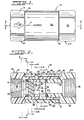
- FIGURE 2 shows a sectional view of the flow-control valve depicted in FIGURE 1 taken along lines 2-2.
- FIGURE 3 shows a cross-sectional view of the flow-control valve in FIGURE 2 taken along lines 3-3.
- FIGURE 4 shows a cross-sectional view of the flow-control valve in FIGURE 2 taken along lines 4-4.
- FIGURE 5 shows a cross-sectional view of the flow-control valve in FIGURE 2 taken along lines 5-5.
- FIGURE 6 shows a cross-sectional view of the flow-control valve in FIGURE 2 taken along lines 6-6.
- FIGURE 7 shows a cross-sectional view of the flow-control valve in FIGURE 2 taken along lines 7-7.
- FIGURES 1 and 2 A flow-control valve, generally indicated by the numeral 10, is illustrated in FIGURES 1 and 2.
- the valve 10 includes a substantially elongated, cylindrical body 12 defining a central bore 14, provided with a fluid inlet 16 at one end.
- An inwardly directed radial wall 9 defines a radial land 11.
- the opposite end of body 12 terminates in a radial stop surface 15.
- Bore 14 includes internal threads 20 adjacent radial stop surface 15.
- Body 12 includes an enlarged hexagonal portion 17, adjacent inlet 16, and the remainder of the body defines a cylindrical portion 19 which extends to radial stop surface 15.
- a circumferential slot 22 extends partially about the circumference of the body 12 in the cylindrical portion 19, and is open to bore 14. In this embodiment, the slot extends about 90 degrees. It terminates in stop surfaces 23.
- the sleeve member 24 is relatively rotatable with respect to body 12.
- a longitudinal groove 26 is formed in the inner cylindrical wall of the sleeve member 24.
- the sleeve member 24 forms the operative element of an operating means for opening and closing the valve as will be explained.
- a fitting 44 is provided which includes a central bore 45 defining a fluid outlet 18.
- An enlarged hexagonal portion 47 is formed adjacent outlet 18.
- An annular cylindrical portion 49 extends from the hexagonal portion 47 and includes threads which mate with threads 20 and body 12.
- the hexagonal portion 47 includes radial stop surface 51 adapted to be abutted by radial stop surface 15 when the fitting 44 is threaded onto threads 20.
- Fitting 44 includes an end opposite outlet 18 which includes a counterbore having a radial land 57. With fitting 44 affixed to threads 20 of body 12 and radial stop surface 15 in abutting relation to radial stop surface 51, radial land 11 of body 12 and radial land 57 of fitting 44 define a seal member receiving chamber within the body 12 of a finite axial length. This chamber receives and retains a seal assembly 28 in fluid tight relation.
- Seal assembly 28 disposed in the seal member receiving chamber in the assembled body and fitting between radial lands 11 and 57, consists of three separate parts, a stationary seal member 30 secured to the body 12 and fixed against rotation, a rotatable seal member 32 rotatable within the housing 12 and a thrust washer 42.
- Each of the seal assembly components is a generally cylindrical disc which includes spaced, parallel planar radial faces.
- the adjacent faces of the non-rotatable member 30, rotatable member 32 and thrust washer 42 are in face-to-face contact. These surfaces are polished to a degree such that this face-to-face contact seals against the flow or leakage of fluid along these mating faces.
- the discs of the seal assembly are preferably made of ceramic. It is contemplated, however, that other materials, such as plastic, carbon graphite, or stainless steel could be utilized for the discs.
- a second radial face of the non-rotatable member 30 faces radial land 11 of body 12.
- a second radial face of the thrust washer 42 faces radial land 57 of the counterbore in the end of fitting 44.
- a seal, in the form of an elastomeric O-ring, 38 is provided between land 11 and the adjacent face of stationary member 30.
- a seal, in the form of an elastomeric O-ring, 48 is provided in the counterbore and is disposed between the adjacent radial face of thrust washer 42 and radial land 57. The axial distance between radial lands 11 and 57 defines the finite axial extent of the seal member receiving chamber.
- seals namely O-rings 38 and 48 are placed in compression between the seal assembly and the radial lands 11 and 57.
- the seals provide a fluid tight seal against the associated radial faces of the seal assembly and the radial stop surfaces 11 and 57 and also provide a predetermined preload upon the discs to urge the contacting faces into fluid tight contact with each other.
- O-ring seals are illustrated, it is contemplated that a variety of seals could be used. Any form of packing is considered acceptable. It is also thought that expandable elastomeric or metallic bellows could be substituted for the O-ring seals illustrated.
- the stationary seal member 30 is pinned to body 12 by pin 70 (FIGURE 5). It includes a pair of flow ports 34, as shown in FIGURE 4. Although two ports 34 are illustrated, the actual number and size of the ports may vary depending upon the flow conditions of the application.
- the rotatable seal member 32 also has a pair of flow ports 36, as shown in FIGURE 6, which correspond with the ports 34.
- Thrust washer 42 has a passage 43 which communicates with ports 36 of rotatable seal member 32.
- the flow ports 36 of the rotatable seal member 32 are arranged relative to the flow ports 34 of the stationary seal member 30 such that rotation of the rotatable seal member 32 varies the size of the orifice defined by the alignment of the corresponding flow ports 34 and 36 of the stationary seal member 30 and the rotatable seal member 32, respectively.
- Rotatable seal member or disc 32 includes a peripheral relief 60 best seen in FIGURE 6.
- Relief 60 extends slightly more than 180 degrees about the periphery of disc 32 and terminates in spaced abutment surfaces 62.
- An operator 64 in the form of an integral thin band lies within relief 60. It includes arcuate legs 66 which conform to the outer peripheral relief 60 and which include ends engaged with abutment surfaces 62.
- An upstanding tab 68 is formed intermediate arcuate legs 66 which, as seen in FIGURES 2 and 6, protrudes from body 12 through slot 22.
- Upstanding tab 68 is disposed within longitudinal groove 26 of outer rotatable sleeve 24 to engage the operator 64 with the sleeve 24. Rotation of the sleeve causes the operator to travel within slot 22.
- the ends of legs 66 thereby impart rotational forces to disc 32 at abutment surfaces 62.
- the length of legs 66 is preferably such that when tab 68 is abutting one stop surface 23 of slot 22, the abutment surface 62 is not exposed within the slot. This insures that the operator 64 will be securely retained within the body 12 and also insures smooth operation of the valve.
- the tab 68 and ports 36 in the rotatable seal member 32 are in axial alignment, thereby providing an index for indicating the position of the disc 32 relative to the disc 30.
- Indicia 70 and 71, seen in FIGURE 1, may be used to provide an external indication of the status of the valve.
- the valve 10 may be assembled by first inserting O-ring 38, seal assembly 28 and O-ring 48 into bore 14 of body 12. Pin 70 is then installed to retain stationary disc 30. Operator 64 may then be inserted through slot 22 with legs 66 disposed in peripheral relief 60 with the ends of the legs against abutment surfaces 62. The operator should be made of steel or suitable plastic to permit the necessary bending or springing of the legs 66 to permit this insertion.
- the valve may also be assembled by inserting O-ring 38 and disc 30 and then placing operator 64 within the bore 14. Operator 64 is positioned with the legs 66 against the inner surface of bore 14 with tab 68 protruding from slot 22. Disc 32, disc 43 and O-ring 48 may then be placed within the cavity with the ends of legs 66 in operating contact with abutment surfaces 62.
- Rotatable sleeve 24 is then slid onto cylindrical portion 19 of body 14 with tab 68 disposed within groove 26. Rotation of the sleeve will thus cause rotation of operator 64 and rotatable disc 32.
- Fitting 44 is tightened onto threads 20 until radial stop surface 15 of body 12 engages radial stop surface 51 of fitting 44.
- the O-rings 38 and 48 and ceramic seal assembly 28 are compressed between radial lands 11 and 57 to seal the ceramic seal assembly within the cavity with the appropriate preload on the ceramic discs to permit rotation of disc 32 and yet prevent leakage across the contacting faces.
- Rotatable sleeve 24 is retained on cylindrical relieved portion 19 between hexagonal ends 17 of body 12 and 47 of fitting 44.
- valve 10 of the present invention is as follows. When the ports 36 of the rotatable seal member 32 are positioned as in FIGURE 2 and 6, the "closed" position, the flow of fluid though the valve 10 is prohibited. In this postion, tab 68 engages one of the two stop surfaces 23 of slot 22. When it is desired to permit the flow of fluid through the valve 10, the sleeve member 24 is rotated counter-clockwise in FIGURE 6, until tab 68 engages the other stop surface 23. This aligns the flow ports 36 in the rotatable seal member 32 with the flow ports 34 in the stationary seal member 30.
- the amount of fluid permitted to flow through the ports 34, 36 can be controlled by varying the degree of rotation and alignment of the ports such that if the sleeve member 24 were rotated 30 or 60 degrees in a counter-clockwise direction, the flow of fluid would not be as great as if the sleeve member 24 were rotated a full 90 degrees.
- the sleeve member 24 is rotated clockwise toward the "closed" position illustrated in FIGURE 6 until the desired result is obtained.
- the seal assembly provides a positive stop against flow of fluid in that, when positioned in the closed position, the planar surface of rotatable seal member 32 that is in contact with stationary member 30, closes off flow ports 34. Further, the face-to-face contact of the radial surfaces of the rotatable member 32, maintained by the preload of O-rings 38 and 48, prevents entry of contaminants along the sealing faces.
- the inclusion of thrust washer 42 in the seal assembly 28 isolates the elastomeric O-ring seals from movement of the rotatable member 32. Relative movement is limited to the planar surfaces of the discs which are in face-to-face contact.
- the present invention provides an in-line flow-control valve with a seal assembly operable from outside the housing, to regulate or prevent the flow of fluid through the valve.
Landscapes
- Engineering & Computer Science (AREA)
- General Engineering & Computer Science (AREA)
- Mechanical Engineering (AREA)
- Sliding Valves (AREA)
- Multiple-Way Valves (AREA)
- Taps Or Cocks (AREA)
Abstract
Description
- The present invention relates to in-line flow-control valves which seal against the flow of fluid through the valve. Arrangements of this general type are shown in the prior art U.S. Patents 263,330; 341,170; 2,556,583; 2,709,566; and 2.883,150. None of these prior art patents teaches a valve formed of a separable body and fitting which define a cavity to house a rotatable seal assembly operable to control fluid flow.
- The present invention provides an in-line flow-control valve incorporating a separable body and fitting which house a rotatable seal assembly operable from outside the body to control the flow of fluid through the valve. The assembled body and fitting define a cavity of finite axial length which receives and retains a seal assembly in fluid tight relation. The seal assembly is comprised of at least one fixed, and one rotatable seal member, having planar surfaces in face-to-face contact. Each seal member contains one or more flow ports which, when aligned, permit flow through the valve. Operating means external to the body and connected to the rotatable seal member, effects rotation of the rotatable member to position the ports of the rotatable seal member either into or out of alignment with the flow ports of the stationary seal member.
- In a preferred form the rotatable seal member includes a peripheral relief defining spaced abutment surfaces. An operator disposed in the peripheral relief has ends in operative contact with the abutment surfaces and includes means extending from the body to effect rotation of the rotatable seal member.
- FIGURE 1 shows a side view of the flow-control valve of the present invention.
- FIGURE 2 shows a sectional view of the flow-control valve depicted in FIGURE 1 taken along lines 2-2.
- FIGURE 3 shows a cross-sectional view of the flow-control valve in FIGURE 2 taken along lines 3-3.
- FIGURE 4 shows a cross-sectional view of the flow-control valve in FIGURE 2 taken along lines 4-4.
- FIGURE 5 shows a cross-sectional view of the flow-control valve in FIGURE 2 taken along lines 5-5.
- FIGURE 6 shows a cross-sectional view of the flow-control valve in FIGURE 2 taken along lines 6-6.
- FIGURE 7 shows a cross-sectional view of the flow-control valve in FIGURE 2 taken along lines 7-7.
- A flow-control valve, generally indicated by the
numeral 10, is illustrated in FIGURES 1 and 2. Thevalve 10 includes a substantially elongated,cylindrical body 12 defining acentral bore 14, provided with afluid inlet 16 at one end. An inwardly directed radial wall 9 defines a radial land 11. The opposite end ofbody 12 terminates in a radial stop surface 15. Bore 14 includesinternal threads 20 adjacent radial stop surface 15.Body 12 includes an enlargedhexagonal portion 17,adjacent inlet 16, and the remainder of the body defines acylindrical portion 19 which extends to radial stop surface 15. As best shown in FIGURE 6, acircumferential slot 22 extends partially about the circumference of thebody 12 in thecylindrical portion 19, and is open to bore 14. In this embodiment, the slot extends about 90 degrees. It terminates instop surfaces 23. - An elongated
annular sleeve member 24 open at both ends overliescylindrical portion 19 ofbody 12. Thesleeve member 24 is relatively rotatable with respect tobody 12. Alongitudinal groove 26 is formed in the inner cylindrical wall of thesleeve member 24. Thesleeve member 24 forms the operative element of an operating means for opening and closing the valve as will be explained. - A
fitting 44 is provided which includes acentral bore 45 defining afluid outlet 18. An enlargedhexagonal portion 47 is formedadjacent outlet 18. An annularcylindrical portion 49 extends from thehexagonal portion 47 and includes threads which mate withthreads 20 andbody 12. Thehexagonal portion 47 includesradial stop surface 51 adapted to be abutted by radial stop surface 15 when thefitting 44 is threaded ontothreads 20. - Fitting 44 includes an end opposite
outlet 18 which includes a counterbore having aradial land 57. Withfitting 44 affixed tothreads 20 ofbody 12 and radial stop surface 15 in abutting relation toradial stop surface 51, radial land 11 ofbody 12 andradial land 57 offitting 44 define a seal member receiving chamber within thebody 12 of a finite axial length. This chamber receives and retains aseal assembly 28 in fluid tight relation. -
Seal assembly 28, disposed in the seal member receiving chamber in the assembled body and fitting betweenradial lands 11 and 57, consists of three separate parts, astationary seal member 30 secured to thebody 12 and fixed against rotation, arotatable seal member 32 rotatable within thehousing 12 and athrust washer 42. - Each of the seal assembly components is a generally cylindrical disc which includes spaced, parallel planar radial faces. The adjacent faces of the non-rotatable
member 30,rotatable member 32 andthrust washer 42 are in face-to-face contact. These surfaces are polished to a degree such that this face-to-face contact seals against the flow or leakage of fluid along these mating faces. The discs of the seal assembly are preferably made of ceramic. It is contemplated, however, that other materials, such as plastic, carbon graphite, or stainless steel could be utilized for the discs. - A second radial face of the non-rotatable
member 30 faces radial land 11 ofbody 12. Similarly, a second radial face of the thrust washer 42 facesradial land 57 of the counterbore in the end of fitting 44. A seal, in the form of an elastomeric O-ring, 38 is provided between land 11 and the adjacent face ofstationary member 30. A seal, in the form of an elastomeric O-ring, 48 is provided in the counterbore and is disposed between the adjacent radial face ofthrust washer 42 andradial land 57. The axial distance betweenradial lands 11 and 57 defines the finite axial extent of the seal member receiving chamber. Upon attachment of fitting 44 tothreads 20 with radial stop surface 15 ofbody 12 in engagement withradial stop surface 51 of fitting 44, seals, namely O-rings radial lands 11 and 57. The seals provide a fluid tight seal against the associated radial faces of the seal assembly and theradial stop surfaces 11 and 57 and also provide a predetermined preload upon the discs to urge the contacting faces into fluid tight contact with each other. - Though O-ring seals are illustrated, it is contemplated that a variety of seals could be used. Any form of packing is considered acceptable. It is also thought that expandable elastomeric or metallic bellows could be substituted for the O-ring seals illustrated.
- The
stationary seal member 30 is pinned tobody 12 by pin 70 (FIGURE 5). It includes a pair offlow ports 34, as shown in FIGURE 4. Although twoports 34 are illustrated, the actual number and size of the ports may vary depending upon the flow conditions of the application. Therotatable seal member 32 also has a pair offlow ports 36, as shown in FIGURE 6, which correspond with theports 34.Thrust washer 42 has apassage 43 which communicates withports 36 ofrotatable seal member 32. Theflow ports 36 of therotatable seal member 32 are arranged relative to theflow ports 34 of thestationary seal member 30 such that rotation of therotatable seal member 32 varies the size of the orifice defined by the alignment of thecorresponding flow ports stationary seal member 30 and therotatable seal member 32, respectively. - Rotatable seal member or
disc 32 includes aperipheral relief 60 best seen in FIGURE 6.Relief 60 extends slightly more than 180 degrees about the periphery ofdisc 32 and terminates in spacedabutment surfaces 62. Anoperator 64 in the form of an integral thin band lies withinrelief 60. It includesarcuate legs 66 which conform to the outerperipheral relief 60 and which include ends engaged with abutment surfaces 62. - An
upstanding tab 68 is formed intermediatearcuate legs 66 which, as seen in FIGURES 2 and 6, protrudes frombody 12 throughslot 22.Upstanding tab 68 is disposed withinlongitudinal groove 26 of outerrotatable sleeve 24 to engage theoperator 64 with thesleeve 24. Rotation of the sleeve causes the operator to travel withinslot 22. The ends oflegs 66 thereby impart rotational forces todisc 32 at abutment surfaces 62. The length oflegs 66 is preferably such that whentab 68 is abutting onestop surface 23 ofslot 22, theabutment surface 62 is not exposed within the slot. This insures that theoperator 64 will be securely retained within thebody 12 and also insures smooth operation of the valve. - The
tab 68 andports 36 in therotatable seal member 32 are in axial alignment, thereby providing an index for indicating the position of thedisc 32 relative to thedisc 30.Indicia - The
valve 10 may be assembled by first inserting O-ring 38,seal assembly 28 and O-ring 48 intobore 14 ofbody 12.Pin 70 is then installed to retainstationary disc 30.Operator 64 may then be inserted throughslot 22 withlegs 66 disposed inperipheral relief 60 with the ends of the legs against abutment surfaces 62. The operator should be made of steel or suitable plastic to permit the necessary bending or springing of thelegs 66 to permit this insertion. - The valve may also be assembled by inserting O-
ring 38 anddisc 30 and then placingoperator 64 within thebore 14.Operator 64 is positioned with thelegs 66 against the inner surface ofbore 14 withtab 68 protruding fromslot 22.Disc 32,disc 43 and O-ring 48 may then be placed within the cavity with the ends oflegs 66 in operating contact with abutment surfaces 62. -
Rotatable sleeve 24 is then slid ontocylindrical portion 19 ofbody 14 withtab 68 disposed withingroove 26. Rotation of the sleeve will thus cause rotation ofoperator 64 androtatable disc 32. - Fitting 44 is tightened onto
threads 20 until radial stop surface 15 ofbody 12 engagesradial stop surface 51 of fitting 44. The O-rings ceramic seal assembly 28 are compressed betweenradial lands 11 and 57 to seal the ceramic seal assembly within the cavity with the appropriate preload on the ceramic discs to permit rotation ofdisc 32 and yet prevent leakage across the contacting faces.Rotatable sleeve 24 is retained on cylindricalrelieved portion 19 between hexagonal ends 17 ofbody - The operation of the
valve 10 of the present invention is as follows. When theports 36 of therotatable seal member 32 are positioned as in FIGURE 2 and 6, the "closed" position, the flow of fluid though thevalve 10 is prohibited. In this postion,tab 68 engages one of the two stop surfaces 23 ofslot 22. When it is desired to permit the flow of fluid through thevalve 10, thesleeve member 24 is rotated counter-clockwise in FIGURE 6, untiltab 68 engages theother stop surface 23. This aligns theflow ports 36 in therotatable seal member 32 with theflow ports 34 in thestationary seal member 30. The amount of fluid permitted to flow through theports sleeve member 24 were rotated 30 or 60 degrees in a counter-clockwise direction, the flow of fluid would not be as great as if thesleeve member 24 were rotated a full 90 degrees. When it is desired to stop, or decrease the flow of fluid through thevalve 10, thesleeve member 24 is rotated clockwise toward the "closed" position illustrated in FIGURE 6 until the desired result is obtained. - The seal assembly provides a positive stop against flow of fluid in that, when positioned in the closed position, the planar surface of
rotatable seal member 32 that is in contact withstationary member 30, closes offflow ports 34. Further, the face-to-face contact of the radial surfaces of therotatable member 32, maintained by the preload of O-rings thrust washer 42 in theseal assembly 28 isolates the elastomeric O-ring seals from movement of therotatable member 32. Relative movement is limited to the planar surfaces of the discs which are in face-to-face contact. - Thus, it has been shown that the present invention provides an in-line flow-control valve with a seal assembly operable from outside the housing, to regulate or prevent the flow of fluid through the valve. Various features of the invention have been particularly shown and described in connection with the illustrated embodiment of the invention, however, it must be understood that these particular arrangements merely illustrate and the invention is to be given its fullest interpretation within the terms of the appended claims.
Claims (39)
- A flow-control valve including a body, a fluid inlet defined in said body, said body including an elongated cylindrical portion having a continuous cylindrical wall defining a cylindrical chamber in communication with said inlet, said cylindrical portion having an open end defining a radial stop surface and said portion further defining a radial land at an end of said continuous cylindrical wall axially spaced from said radial stop surface, a separable fitting threadedly engaged with said body defining a fluid outlet, said fitting having an elongated cylindrical portion defining a passage in communication with said fluid outlet and said cylindrical chamber of said body, said cylindrical portion having a radial stop surface adjacent one end thereof in engagement with the radial stop surface of said elongated cylindrical portion of said body, said cylindrical portion of said fitting extending interiorly of said continuous cylindrical wall of said body and terminating at an end defining a radial land, said radial land defining with said radial land of said body a seal assembly receiving cavity of finite length, a ceramic seal assembly disposed in said chamber between said inlet and said outlet, at least two annular elastomeric seal members, each of which is compressed between one of said radial lands, said ceramic seal assembly and said continuous cylindrical wall, said seal assembly including a stationary, ceramic seal member nonrotatably mounted with respect to said housing, said stationary member defining one or more flow ports therethrough, a rotatable, ceramic seal member disposed adjacent to and in face-to-face contact with said stationary seal member, said rotatable seal member defining one or more ports therethrough, operator means outside the housing connected to said rotatable seal member operable to selectively position said ports of said rotatable seal member into and out of alignment with said ports of said stationary seal member.
- A valve as in Claim 1 in which said operator means includes an elongated sleeve member overlying said cylindrical portion of said body relatively rotatable with respect thereto and a member extending from said rotatable seal member and connected to said sleeve member for selective positioning of said rotatable seal member with respect to said stationary seal member.
- A valve as in Claim 1 in which said ports of said rotatable and stationary seal members are arranged such that relative rotation of said seal members between predetermined points varies the size of the orifice defined by the alignment of corresponding ports of said rotatable and stationary seal members.
- A valve as in Claim 1 including an elastomeric seal member disposed between said stationary seal member and said housing.
- A valve as in Claim 1 including a ceramic thrust washer disposed between said housing and said rotatable seal member such that said rotatable seal member is compressed between said stationary seal member on one side and said thrust washer on said other side.
- A valve as in Claim 1 including a removable fitting adapted to be secured to said housing and to exert force against said thrust washer.
- A valve as in Claim 6 including an elastomeric seal member disposed between said removable fitting and said thrust washer.
- A valve as in Claim 1 in which said inlet is axially aligned with said outlet.
- An in-line flow-control valve for controlling the flow of fluid, said valve comprising an elongated body defining a flow passage having an inlet, a separable fitting secured to said body defining a flow passage in communication with said flow passage of said body and defining an outlet;
said body including an elongated cylindrical portion having a continuous cylindrical wall defining a cylindrical chamber in communication with said inlet, said cylindrical portion having an open end defining a radial stop surface and said portion further defining a radial land at an end of said continuous cylindrical wall axially spaced from said radial stop surface, a separable fitting threadedly engaged with said body defining a fluid outlet, said fitting having an elongated cylindrical portion defining a passage in communication with said fluid outlet and said cylindrical chamber of said body, said cylindrical portion having a radial stop surface adjacent one end thereof in engagement with the radial stop surface of said elongated cylindrical portion of said body, said cylindrical portion of said fitting extending interiorly of said continuous cylindrical wall of said body and terminating at an end defining a radial land, said radial land defining with said radial land of said body a seal assembly receiving cavity of finite length, at least two annular elastomeric seal members, each of which is compressed between one of said radial lands, said seal assembly and said continuous cylindrical wall;
a seal assembly disposed within said cavity in fluid tight relation;
said seal assembly comprising at least one fixed, and one rotatable seal member having planar surfaces in face-to-face sealing contact, each such member containing at least one flow port which when aligned, permits flow through said valve;
said planar surface of said rotatable member being adapted to selectively close said at least one port of said stationary seal member; and
operating means external to said body connected to said rotatable seal member to effect rotation thereof. - An in-line flow-control valve as claimed in Claim 9 wherein said operating means includes an elongated sleeve rotatably received upon said elongated cylindrical portion connected to said rotatable seal member.
- An in-line flow-control valve as claimed in Claim 10 wherein said body includes an enlarged hexagonal portion adjacent said inlet and said fitting includes an enlarged hexagonal portion adjacent said outlet, and said sleeve is rotatably received and retained upon said body between said hexagonal portions.
- An in-line flow-control valve as claimed in Claim 10 wherein said operating means includes an operator connecting said sleeve to said rotatable seal member.
- An in-line flow-control valve as claimed in Claim 12 wherein said cylindrical portion of said body includes a circumferential slot extending partially therearound, said operator includes a tab extending from said body through said slot, and said sleeve includes a longitudinal groove which receives said tab.
- An in-line flow-control valve as claimed in Claim 13 wherein said rotatable seal member comprises a disc, said disc having a peripheral relief defining spaced abutment surfaces, said operator includes arcuate legs extending from said tab conforming to said outer peripheral relief and having ends engaging said abutment surfaces.
- An in-line flow-control valve as claimed in Claim 10 wherein said abutment surfaces are about 180 degrees apart upon said periphery of said rotatable member.
- An in-line flow-control valve as claimed in Claim 14 wherein said operator comprises an integral thin band defining said arcuate legs and said upstanding tab.
- An in-line flow-control valve as claimed in Claim 14 wherein said circumferential slot terminates in stop surfaces about 90 degrees apart, engagement of said tab with said stop surfaces defining the limit of rotation of said sleeve.
- An in-line flow-control valve as claimed in Claim 9, including means applying a predetermined pre-load upon said planar surfaces of said seal members to urge said planar faces into face-to-face sealing contact.
- An in-line flow-control valve as claimed in Claim 18 including at least one O-ring in said cavity in compression between said seal assembly and one of said radial lands.
- An in-line flow-control valve as claimed in Claim 19 including two O-rings each one of which is in compression between said seal assembly and one of said lands.
- An in-line flow-control valve as claimed in Claim 20 wherein said seal assembly includes a thrust washer having a flow passage therethrough in fluid communication with the said at least one flow port of said rotatable seal member, said thrust washer and said rotatable seal member including planar surfaces in face-to-face sealing contact.
- An in-line flow-control valve as claimed in Claim 21 wherein said stationary seal member and said thrust washer each include a second planar face spaced from said planar faces in face-to-face sealing contact with said rotatable seal member, one of said O-rings being compressed between one of said lands and said second planar face of said stationary member and the other of said O-rings being compressed between said second planar face of said thrust washer and the other of said lands.
- An in-line flow-control valve as claimed in Claim 9 wherein said seal members comprise ceramic discs.
- An in-line flow-control valve as claimed in Claim 22 wherein said seal members comprise ceramic discs.
- An in-line flow-control valve for controlling the flow of fluid, said valve defining a flow passage having an inlet, an outlet, and a seal assembly receiving cavity and a circumferential slot open to said cavity;
a seal assembly disposed within said cavity in fluid tight relation;
said seal assembly comprising at least one fixed, and one rotatable disc having planar surfaces in face-to-face sealing contact, each such disc containing at least one flow port which when aligned, permits flow through said valve;
said planar surface of said rotatable disc being adapted to selectively close said at least one port of said stationary seal member; and
operating means external to said body connected to said rotatable disc to effect rotation thereof, said operating means including a peripheral relief defining spaced abutment surfaces and an operator extending from said valve through said slot and including legs engaging said abutment surfaces. - An in-line flow-control valve as claimed in Claim 25 wherein said body includes an elongated cylindrical portion, and said operating means includes an elongated sleeve rotatably received upon said elongated cylindrical portion connected to said rotatable disc.
- An in-line flow-control valve as claimed in Claim 26 wherein said body includes an enlarged hexagonal portion adjacent said inlet and said fitting includes an enlarged hexagonal portion adjacent said outlet, and said sleeve is rotatably received and retained upon said body between said hexagonal portions.
- An in-line flow-control valve as claimed in Claim 25 wherein said operator includes a tab extending from said body through said slot, and said sleeve includes a longitudinal groove which receives said tab.
- An in-line flow-control valve as claimed in Claim 25 wherein said abutment surfaces are about 180 degrees apart upon said periphery of said rotatable member.
- An in-line flow-control valve as claimed in Claim 28 wherein said operator comprises an integral thin band defining said arcuate legs and said upstanding tab.
- An in-line flow-control valve as claimed in Claim 28 wherein said circumferential slot terminates in stop surfaces about 90 degrees apart, engagement of said tab with said stop surfaces defining the limit of rotation of said sleeve.
- An in-line flow-control valve as claimed in Claim 25 including means applying a predetermined pre-load upon said planar surfaces of said discs to urge said planar faces into face-to-face sealing contact.
- An in-line flow-control valve as claimed in Claim 25 including at least one O-ring in said cavity compressed against said seal assembly.
- An in-line flow-control valve as claimed in Claim 33 including two O-rings each one of which is compressed against said seal assembly.
- An in-line flow-control valve as claimed in Claim 21 wherein said seal assembly includes a thrust washer having a flow passage therethrough in fluid communication with the said at least one flow port of said rotatable disc, said thrust washer and said rotatable disc including planar surfaces in face-to-face sealing contact.
- An in-line flow-control valve as claimed in Claim 35 wherein said stationary disc and said thrust washer each include a second planar face spaced from said planar faces in face-to-face sealing contact with said rotatable disc, one of said O-rings being compressed against said second planar face of said stationary disc and the other of said O-rings being compressed against said second planar face of said thrust washer.
- An in-line flow control valve as claimed in Claim 36 wherein said discs are made of ceramic.
- An in-line flow control valve as claimed in Claim 25 wherein said discs are made of ceramic.
- An in-line flow control valve as claimed in Claim 34 wherein said discs are made of ceramic.
Applications Claiming Priority (2)
| Application Number | Priority Date | Filing Date | Title |
|---|---|---|---|
| US07/166,466 US4848403A (en) | 1988-03-10 | 1988-03-10 | Flow-control valve |
| US166466 | 1998-10-05 |
Publications (2)
| Publication Number | Publication Date |
|---|---|
| EP0333015A2 true EP0333015A2 (en) | 1989-09-20 |
| EP0333015A3 EP0333015A3 (en) | 1990-10-24 |
Family
ID=22603421
Family Applications (1)
| Application Number | Title | Priority Date | Filing Date |
|---|---|---|---|
| EP19890104104 Withdrawn EP0333015A3 (en) | 1988-03-10 | 1989-03-08 | Flow-control valve |
Country Status (6)
| Country | Link |
|---|---|
| US (1) | US4848403A (en) |
| EP (1) | EP0333015A3 (en) |
| JP (1) | JPH01283481A (en) |
| KR (1) | KR890014931A (en) |
| AU (1) | AU619810B2 (en) |
| CA (1) | CA1311461C (en) |
Cited By (6)
| Publication number | Priority date | Publication date | Assignee | Title |
|---|---|---|---|---|
| RU2158387C1 (en) * | 1999-02-04 | 2000-10-27 | Гельфенбуйм Исаак Викторович | Gate-valve cut-off assembly |
| WO2003027549A1 (en) * | 2001-09-21 | 2003-04-03 | Micro Mechatronic Technologies Ag | Flow rate adjusting device |
| RU2206009C2 (en) * | 2001-07-30 | 2003-06-10 | Бархатов Борис Гаврилович | Cock |
| EP1666147A1 (en) * | 2004-11-18 | 2006-06-07 | H. Lüdi + Co. AG | Laboratory fitting with shut-off mechanism |
| EP1760375A1 (en) * | 2005-09-06 | 2007-03-07 | Effebi S.p.A. | Valve for regulating and/or intercepting fluids |
| DE10347821B4 (en) * | 2003-10-10 | 2009-09-17 | Grohe Ag | Valve with actuator |
Families Citing this family (31)
| Publication number | Priority date | Publication date | Assignee | Title |
|---|---|---|---|---|
| US5312049A (en) * | 1992-07-16 | 1994-05-17 | Bayler Howard O | Improved valve mechanism for a nozzle |
| US6341762B1 (en) | 1999-05-18 | 2002-01-29 | Lockheed Martin Corporation | Service valve and use of same in reaction control system |
| WO2003006855A1 (en) * | 2000-04-07 | 2003-01-23 | Liu, Xin | A ceramics sealing three way valve |
| US6651901B2 (en) * | 2001-03-20 | 2003-11-25 | Corrigan Corporation Of America | Misting system nozzle holder with manual slide shut-off valve |
| US6913245B2 (en) * | 2002-07-18 | 2005-07-05 | Michael G. Jacoway | In-line shut-off valve and method of assembling same |
| US20060005888A1 (en) * | 2004-07-12 | 2006-01-12 | Chung-I Huang | Flow control apparatus |
| US7163027B2 (en) * | 2004-07-20 | 2007-01-16 | Mike Hwang | Air tap assembly |
| US7156120B2 (en) * | 2004-07-28 | 2007-01-02 | Cct Manufacturing, Inc. | Inline liquid flow control valve |
| US7114515B2 (en) * | 2005-02-28 | 2006-10-03 | American Standard Europe B.V.B.A. | In-line valve cartridge |
| US7726338B2 (en) * | 2007-10-26 | 2010-06-01 | Uponor Innovation Ab | Valve with ceramic discs |
| US8297305B2 (en) * | 2008-01-28 | 2012-10-30 | Kohler Co. | Valve assembly having an improved flow path |
| US20100019488A1 (en) * | 2008-07-28 | 2010-01-28 | Weimer Norris R | Hose Coupling with Flow Control |
| US20100122742A1 (en) * | 2008-11-20 | 2010-05-20 | Hsiao-Mei Lin | Fluid control throttle valve |
| WO2012024624A1 (en) * | 2010-08-20 | 2012-02-23 | Py Daniel C | Connector and related method |
| AU2014202753B2 (en) * | 2013-08-09 | 2015-04-02 | NOTT, Owen Edward Lindsay | Valve and method of purging a utilities pipe |
| FR3012196B1 (en) * | 2013-10-18 | 2016-05-13 | Air Liquide | GAS FLOW REGULATOR, DETENDOR, TAP AND BOTTLE PROVIDED WITH SUCH REGULATOR |
| US9400057B2 (en) * | 2014-04-02 | 2016-07-26 | Griswold Controls, Llc | Axially aligned rotationally adjustable flow control valve |
| EP2985498A1 (en) * | 2014-08-12 | 2016-02-17 | Griswold Controls Corporation | An axially aligned rotationally adjustable flow control valve |
| US10584468B2 (en) | 2016-03-24 | 2020-03-10 | Knarf, Llc | Universal adapter and method for manufacturing the universal adapter |
| US9982421B2 (en) | 2016-03-24 | 2018-05-29 | Knarf, Llc | Diverter and method for manufacturing the diverter |
| US9896825B2 (en) | 2016-03-24 | 2018-02-20 | Frank L. DiDea | Method for diverting a flow of a fluid |
| US10370833B2 (en) | 2016-03-24 | 2019-08-06 | Knarf, Llc | Fluid delivery system and method |
| US9841132B2 (en) * | 2016-05-10 | 2017-12-12 | Mei Thung Co., Ltd. | Quick connector |
| US10113661B2 (en) | 2016-08-30 | 2018-10-30 | Griswold Controls, Llc | Flow control valve |
| EP3509754B1 (en) | 2016-09-08 | 2021-06-30 | Water Pik, Inc. | Pause assembly for showerheads |
| US10378666B2 (en) * | 2017-06-15 | 2019-08-13 | Banza Stamping Industry Corp. | Adjustable pressure valve |
| US10385978B2 (en) | 2017-10-21 | 2019-08-20 | Hector Hernandez | Cartridge assembly for regulating flows |
| IT201900002529A1 (en) * | 2019-02-21 | 2020-08-21 | Giacomini Spa | VALVE FOR HYDRAULIC REGULATION AND BALANCING OF FLUID FLOW |
| US11493136B1 (en) * | 2021-10-25 | 2022-11-08 | conservalve, LLC | Discrete step, maximum flow-rate-selectable valve |
| WO2024254679A1 (en) * | 2023-06-12 | 2024-12-19 | Muhammad Nouman Khan | Improved valve for controlling fluid flow |
| EP4495471A1 (en) * | 2023-07-20 | 2025-01-22 | Goodrich Corporation | Water port closure assembly |
Family Cites Families (13)
| Publication number | Priority date | Publication date | Assignee | Title |
|---|---|---|---|---|
| GB296164A (en) * | 1927-07-05 | 1928-08-30 | Joseph Herman Dine | Improvements in and relating to valves and cocks for gas and other fluids |
| US2556583A (en) * | 1944-12-04 | 1951-06-12 | Gustav R Hinz | Valve |
| US2709566A (en) * | 1953-08-07 | 1955-05-31 | Catawissa Valve & Fittings Co | Orifice union for pipe lines |
| US2883150A (en) * | 1957-05-31 | 1959-04-21 | United Shoe Machinery Corp | Strain wave rotary valve |
| DE1153581B (en) * | 1959-03-14 | 1963-08-29 | Friedrich Gampper K G Metallwa | Shut-off and throttling device for fluid lines with a rotary valve |
| US3331396A (en) * | 1964-09-14 | 1967-07-18 | Willis N Elizabeth | Orifice valve |
| US3426797A (en) * | 1965-10-20 | 1969-02-11 | Willis Oil Tool Co | Multiple orifice valve |
| FR1501194A (en) * | 1965-11-11 | 1967-11-10 | Mcconnel F W Ltd | Improvements to hydraulic control valves |
| FR1454755A (en) * | 1965-11-22 | 1966-10-07 | American Radiator & Standard | Ceramic valve parts and process for their manufacture |
| FR2161194A5 (en) * | 1971-11-17 | 1973-07-06 | Guinard Pompes | |
| US4098294A (en) * | 1976-10-15 | 1978-07-04 | Woods John B | Flow control valve |
| DE3309545A1 (en) * | 1983-03-17 | 1984-09-20 | Ideal-Standard Gmbh, 5300 Bonn | 2-WAY VALVE |
| US4554948A (en) * | 1984-06-22 | 1985-11-26 | American Standard Inc. | Straight-way valve |
-
1988
- 1988-03-10 US US07/166,466 patent/US4848403A/en not_active Expired - Fee Related
-
1989
- 1989-03-08 EP EP19890104104 patent/EP0333015A3/en not_active Withdrawn
- 1989-03-09 KR KR1019890002905A patent/KR890014931A/en not_active Withdrawn
- 1989-03-10 CA CA000593289A patent/CA1311461C/en not_active Expired - Fee Related
- 1989-03-10 JP JP1059483A patent/JPH01283481A/en active Pending
- 1989-03-10 AU AU31214/89A patent/AU619810B2/en not_active Ceased
Cited By (6)
| Publication number | Priority date | Publication date | Assignee | Title |
|---|---|---|---|---|
| RU2158387C1 (en) * | 1999-02-04 | 2000-10-27 | Гельфенбуйм Исаак Викторович | Gate-valve cut-off assembly |
| RU2206009C2 (en) * | 2001-07-30 | 2003-06-10 | Бархатов Борис Гаврилович | Cock |
| WO2003027549A1 (en) * | 2001-09-21 | 2003-04-03 | Micro Mechatronic Technologies Ag | Flow rate adjusting device |
| DE10347821B4 (en) * | 2003-10-10 | 2009-09-17 | Grohe Ag | Valve with actuator |
| EP1666147A1 (en) * | 2004-11-18 | 2006-06-07 | H. Lüdi + Co. AG | Laboratory fitting with shut-off mechanism |
| EP1760375A1 (en) * | 2005-09-06 | 2007-03-07 | Effebi S.p.A. | Valve for regulating and/or intercepting fluids |
Also Published As
| Publication number | Publication date |
|---|---|
| EP0333015A3 (en) | 1990-10-24 |
| CA1311461C (en) | 1992-12-15 |
| AU619810B2 (en) | 1992-02-06 |
| AU3121489A (en) | 1989-09-14 |
| KR890014931A (en) | 1989-10-25 |
| JPH01283481A (en) | 1989-11-15 |
| US4848403A (en) | 1989-07-18 |
Similar Documents
| Publication | Publication Date | Title |
|---|---|---|
| EP0333015A2 (en) | Flow-control valve | |
| US4572239A (en) | High pressure ball valve | |
| EP0086832B1 (en) | High pressure ball valve | |
| US3556476A (en) | Butterfly valve having improved positive closure means | |
| CA2387226C (en) | Plug valve having seal segments with booster springs | |
| US5327923A (en) | Valve for installation on a pressurized fluid flow line | |
| US4844413A (en) | Shut-off/equalizing valve with molded seals | |
| EP0156574B1 (en) | A rotary valve operating mechanism | |
| US4076211A (en) | Ball valve | |
| US4026516A (en) | Ball valve stem guide | |
| US5152320A (en) | Reverse-acting diverter valve | |
| US3929316A (en) | Non-floating seat structure for expanding gate valves | |
| US4548385A (en) | Flexible seal for rotor valves | |
| US4339110A (en) | Butterfly valve | |
| US4682758A (en) | Disk/stem connection apparatus for butterfly valve | |
| US4575045A (en) | Rotary cock with generally spherical valve member | |
| US3951380A (en) | Demountable valve | |
| US4138090A (en) | Butterfly valve with two-way pressure enhanced sealing | |
| US3888460A (en) | Ball valve compression seat | |
| US4763877A (en) | Butterfly valve seal arrangement | |
| US6186476B1 (en) | Shut-off valve for pipes | |
| US4601307A (en) | Lubricated plug valve | |
| US4513779A (en) | Metering valve | |
| CA1156637A (en) | Plug valve for reduced leakage | |
| US5590683A (en) | Compensating relief valve |
Legal Events
| Date | Code | Title | Description |
|---|---|---|---|
| PUAI | Public reference made under article 153(3) epc to a published international application that has entered the european phase |
Free format text: ORIGINAL CODE: 0009012 |
|
| AK | Designated contracting states |
Kind code of ref document: A2 Designated state(s): AT BE CH DE ES FR GB GR IT LI LU NL SE |
|
| RBV | Designated contracting states (corrected) |
Designated state(s): CH DE FR IT LI NL SE |
|
| PUAL | Search report despatched |
Free format text: ORIGINAL CODE: 0009013 |
|
| AK | Designated contracting states |
Kind code of ref document: A3 Designated state(s): AT BE CH DE ES FR GB GR IT LI LU NL SE |
|
| 17P | Request for examination filed |
Effective date: 19901122 |
|
| 17Q | First examination report despatched |
Effective date: 19920917 |
|
| STAA | Information on the status of an ep patent application or granted ep patent |
Free format text: STATUS: THE APPLICATION IS DEEMED TO BE WITHDRAWN |
|
| 18D | Application deemed to be withdrawn |
Effective date: 19931001 |
|
| REG | Reference to a national code |
Ref country code: EE Ref legal event code: QB4A Ref document number: E003985 Country of ref document: EE Free format text: EXCLUSIVE LICENSE UNTIL TSILSELI Name of requester: SNPE MATERIAUX ENERGETIQUES Effective date: 20101208 |