EP0332890A2 - Cancellation of noise from a noise-degraded voice signal - Google Patents
Cancellation of noise from a noise-degraded voice signal Download PDFInfo
- Publication number
- EP0332890A2 EP0332890A2 EP89103032A EP89103032A EP0332890A2 EP 0332890 A2 EP0332890 A2 EP 0332890A2 EP 89103032 A EP89103032 A EP 89103032A EP 89103032 A EP89103032 A EP 89103032A EP 0332890 A2 EP0332890 A2 EP 0332890A2
- Authority
- EP
- European Patent Office
- Prior art keywords
- noise
- frequencies
- cancellation system
- narrowband
- sensor
- Prior art date
- Legal status (The legal status is an assumption and is not a legal conclusion. Google has not performed a legal analysis and makes no representation as to the accuracy of the status listed.)
- Granted
Links
Images

Classifications
-
- G—PHYSICS
- G10—MUSICAL INSTRUMENTS; ACOUSTICS
- G10L—SPEECH ANALYSIS OR SYNTHESIS; SPEECH RECOGNITION; SPEECH OR VOICE PROCESSING; SPEECH OR AUDIO CODING OR DECODING
- G10L21/00—Processing of the speech or voice signal to produce another audible or non-audible signal, e.g. visual or tactile, in order to modify its quality or its intelligibility
- G10L21/02—Speech enhancement, e.g. noise reduction or echo cancellation
- G10L21/0208—Noise filtering
- G10L21/0216—Noise filtering characterised by the method used for estimating noise
- G10L2021/02161—Number of inputs available containing the signal or the noise to be suppressed
- G10L2021/02165—Two microphones, one receiving mainly the noise signal and the other one mainly the speech signal
Landscapes
- Engineering & Computer Science (AREA)
- Human Computer Interaction (AREA)
- Quality & Reliability (AREA)
- Signal Processing (AREA)
- Health & Medical Sciences (AREA)
- Audiology, Speech & Language Pathology (AREA)
- Computational Linguistics (AREA)
- Physics & Mathematics (AREA)
- Acoustics & Sound (AREA)
- Multimedia (AREA)
- Soundproofing, Sound Blocking, And Sound Damping (AREA)
- Filters That Use Time-Delay Elements (AREA)
- Noise Elimination (AREA)
Abstract
Description
- The present invention, generally, relates to a method of and a system for cancelling noise from noise-corrupted speech and, more particularly, to an improved method of and system for rendering speech recognizable in a high noise environment, particularly where noise is distributed.
- One glance into the cockpit of today's commercial airliner would give an idea of the hands-busy, eyes-busy environment that exists there, and this is more true of the cockpit in today's military aircraft. The military has solved their problem somewhat by the use of voice-actuated controls for many activities, such as located in the cockpit of a fighter aircraft, and this has been accomplished through the use of voice recognition systems.
- It was realized early that, due to the relatively high noise in the cockpit of a fighter aircraft, some form of noise cancellation was required, and from that need, an adaptive filter noise cancellation technique was developed that has become a standard in the industry. More recently, that technique was tried in military helicopters, and it was found to be ineffective.
- It is understandable that the presence of high levels of noise in an audio signal will produce a substantial reduction in the intelligibility of speech, and it has been found that the most advanced voice recognition equipment is seriously ineffective in recognizing the simplest words in the high noise levels encountered in the cockpit of today's tactical fighter aircraft. A technique that was proposed by Bernard Widrow et al. in 1975, known as Adaptive Noise Cancellation (or ANC), has been tested extensively at the Research Laboratory of Electronics at the Massachusetts Institute of Technology.
- The Widrow technique is described in an article that is entitled "Adaptive Noise Cancelling: Principles and Applications", Proc. IEEE, Vol. 63, No. 12, December, 1975.
- During the M.I.T. tests, some improvements were developed in the Widrow technique, such as placements for the two microphones in a fighter cockpit environment as being one inside the oxygen facemask of the pilot and the second microphone outside the facemask. The one microphone, called the "primary" microphone, is located to sense, or to detect, the voice of the pilot plus the noise.
- The second, or "reference", microphone is located to sense, or detect, principally the noise. By locating the reference microphone outside the oxygen facemask, very little of the pilot's voice is picked up.
- The engineers at M.I.T. learned also that it is better to have the signal-to-noise ratio of the primary microphone large compared to the signal-to-noise ratio of the reference microphone, so that the adaptive filter can be kept as small as possible. Otherwise, the adaptive filter must either estimate the delay between the primary and reference signals or have a long impulse response in order to provide good cancellation of the noise from the primary signal.
- A report of the M.I.T. engineers is given in a paper entitled "Adaptive Noise Cancellation in a Fighter Cockpit Environment " by Harrison, Lim and Singer, 1984 IEEE, pages 18A.4.1 through 18A.4.4.
- With all of the expertise of these M.I.T. the engineers, conclusion was that the Adaptive Noise Cancellation technique of Widrow, while effective enough in an environment with a localized noise source, degrades in performance when there is more than one noise source present or when the noise source is distributed over a region. Actually, the many sources of noise in a helicopter make the Adaptive Noise Cancellation technique virtually ineffective in that high noise environment where the noise sources are distributed over a wide region. While those experts in the field departed to study the use of additional reference microphones in a distributed noise environment, the present invention proceeds with the development of a unique solution to this perplexing problem.
- A review of the prior patent art reveals very little to assist in developing a solution such as provided by the present invention. For example, U.S. patent No. 4,625,083 to Poikela is concerned with providing a voice operated switch that is capable of distinguishing between voice and noise. By using one microphone primarily for speech and one microphone primarily for ambient noise signals, each of these groups of signals have a certain sound pressure level, and since it is desired to have the sound pressure level of the speech signal always exceed that of the noise signal, this is accomplished in two ways. One way is by placing the two microphones in predetermined locations so that the sound pressure level distinctions are realized, and another way is by limiting the width of the frequencies, like that customarily used in telephone receivers. A typical frequency range is 100 hertz to 4 kilohertz, but a narrower frequency range of 250 hertz to 3.5 kilohertz is termed as being satisfactory. By connecting both signals to a differential amplifier, an output will result when there is speech, and there is no output when there is no speech.
- U.S. patent No. 4,649,505 to Zinser, Jr. et al. is an example of another attempt to improve on the basic adaptive filter of Widrow, identified supra, but this effort is for the purpose of eliminating crosstalk between speech and noise signals. It discloses the use of a speech input, a noise input and a reference input with a reference noise portion and a crosstalk speech portion to a digital signal processing microcontroller, a read-only-memory and a random access memory, from which the signals are processed digitally. After the inputs are converted first from analog to digital signals, they are converted next from digital serial signals to digital parallel signals for further processing. There is no mention of the problem with which the present invention is concerned.
- U.S. patent No. 4,658,426 to Chabries et al. discloses several different forms of noise suppression devices for use where the signal-to-noise ratio is poor at the input and where the characteristics of the adaptive filter adjust automatically to variations in the input signal. These adjustments utilize time and frequency domains in making the adaptive filter adjustments in order to filter noise, and a mathematical description is given in substantial detail for devices constructed to take advantage of such premises. A use for such devices is given as one tuned to filter out the normal operating sound of machinery as "noise" and to detect the unusual sound of a worn or failed component of the machinery. However, these are illustrations of localized noise, with which the adaptive filter type of device is capable of functioning quite adequately, according to the M.I.T. reference, supra.
- U.S. patent No. 4,672,674 to Clough et al. discloses a system utilizing two specially built microphones that have good near field response and poor far field response to produce signals with noise components having high correlation. Like the Poikela patent No. 4,625,083 above, the outputs from these microphones are connected to a filter to remove frequencies outside the range of 300 Hz to between 5 and 8 kHZ. The signals then pass to analog-to-digital converters, to micro-processor circuitry having delay and other capability, to achieve weighted-factor-samples for further processing. While this prior patent discloses the use of two microphones, it also suggests that a logical extension of this use is to use three or more microphones, one for speech and the outputs of the other microphones being used to cancel the noise in the signal from the one microphone.
- On the other hand, the present invention takes a different approach to providing a solution to the problem of cancelling distributed noise from a speech signal, because tests show that the Adaptive Noise Cancellation technique of the prior art degrades in performance when the noise is distributed over a region.
- It is a principal object of the present invention to provide a system for cancelling distributed noise from a signal that contains noise-degraded speech.
- An important object of the invention is to provide a method for cancelling distributed noise from a voice signal.
- Another object of the present invention is to provide a new and improved method and means for cancelling distributed noise from a voice signal.
- Yet another object of the invention is to provide a noise cancellation method and system that is effective in a high distributed noise environment.
- Still another object of the invention is to provide an effective noise cancellation method and system for use with a speech (or voice) recognition system.
- A further object of the present invention is to provide a noise cancellation method and system that will function effectively with standard speech (or voice) sensing pickups.
- A still further object of the present invention is to provide a noise cancellation method and system that will function effectively with a standard speech or voice) recognition system in a helicopter environment.
- Briefly, a method and system that is constructed and arranged in accordance with the present invention includes two sensors, or microphones, located so that a first sensor will detect both voice and noise and a second sensor will detect principally only the noise. The voice picked up at the second sensor is negligible, and the noise that is picked up at both sensors is correlated. The signal output from each sensor is connected to means to divide each respective signal output into a predetermined number of frequencies. Then, both signal outputs are connected to a circuit to cancel effectively the noise component from the signal output with both voice and noise.
- The present invention will be described with reference to the accompanying drawings, in which:
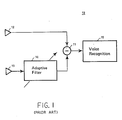
- FIG. 1 is an illustration of a conventional noise cancellation circuit that has become an industry standard.
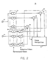
- FIG. 2 is an illustration of a noise cancellation system that embodies the features of the invention.
- FIG. 3 is a curve for use in describing the operation of the system of the invention.
- In FIG. 1 of the drawings, the conventional, or "standard", noise cancellation technique is illustrated in the form it was introduced first by Bernard Widrow et al. in 1975, and is identified generally by the
reference numeral 10. As a system, this technique is considered usually as the input for a voice recognition system. Noise cancellation is performed in asubstract circuit 11 between one signal received directly from onemicrophone 12 and the output from asecond microphone 13 after it is passed through anadaptive filter 14. The output from thesubstract circuit 11 is connected directly to avoice recognition system 15. - The outputs from the two
microphones adaptive filter 14 in this standard technique, therefore, must be capable of performing effectively over the entire audible voice frequency range. - The
adaptive filter 14 in the conventional technique must provide compensating amplitude and phase capabilities that vary greatly from one end of the voice frequency range to the other end. In addition, such anadaptive filter 14 would require a large number of adjustable elements; for example, 100 tap coefficient adjustments, or just "taps", all of which leads to problems, such as: - 1) The adjustment of a large number of control elements (using the conventional gradient method, or the like) is a very slow process.
- 2) Efforts to speed up the process of working with a large number of control elements can produce other problems, such as numerical instability due to truncation errors, rounding errors, statistical averaging errors, etc.
- Noise that is detected by the
microphones - It is an important function that is performed by the
adaptive filter 14, therefore, when it compensates for the differences in time between the two noise frequencies. It is this compensation between the two signals that results in an effective cancellation when they are combined in thesubstract circuit 11. - When the circuit illustrated in FIG. 1, therefore, was tried with noise that was distributed over a region, it was immediately apparent that its performance was degraded seriously relative to its performance with a single localized noise source. Although much effort has been devoted to solving this problem in recent years, none has been effective until the present invention.
- In FIG. 2 of the drawings there is illustrated a circuit arrangement to solve the problem of effectively cancelling the noise from voice, or similar information signals, sufficiently for a voice recognition system to be useful reliably. A noise cancellation system in accordance with the invention is sufficiently effective to be useful in every known environment where noise-degraded speech renders a voice recognition system ineffective; such as, for example, in a factory, on a manufacturing floor, in large office areas, at airports, etc., etc.
- Referring now to FIG. 2, a system that is constructed and arranged in accordance with the principles of the invention is identified generally by the
reference numeral 16. Twostandard sensors sensor 17 detects both voice and noise. It is contemplated that thesensor 17 will be located so that it will detect as much voice as possible, even though that signal is degraded by noise. - The
sensor 18, however, is located so that it will detect principally noise and very little of the voice. When used in a pilot's environment, thesensor 17 is located inside of the pilot's oxygen facemask and thesensor 18 is located outside the oxygen facemask. In other environments, where a wire-like headset is used, thesensor 17 is located close to the mouth of a speaker, and thesensor 18 is located also on the headset but as far as possible from the mouth of the speaker and is pointed in such a way that it detects principally noise. It is important to note, however, that the distance between the twosensors - The signals detected by each of the
sensors - In FIG. 2, the signal output from each of the
sensors sensor 17 are in a group that is identified generally by thereference numeral 19, and thc narrowband filters that are connected to receive the signal output from thesensor 18 are in a group that is identified generally by thereference numeral 20. - Since the usual frequency range for the voice signals spans approximately 3 kHz (or 3000 Hertz), by dividing this range into 15 different bandwidths, each one of the narrowband filters in the two
groups - Any particular number of
narrowband filters sensor sensors - Each of the narrowband filters in the
group 20 is connected to an adaptive filter in a group that is identified by thereference numeral 21. Each of the adaptive filters in thegroup 21 functions to compensate for the amplitude and phase differences in the signal detected by thesensor 18. By this means, when each of the divided signals is combined in each circuit in a group that is identified by thereference numeral 22, the noise signal from thesensor 18 is subtracted from the voice-plus-noise signal from thesensor 17 to provide the substantially noise-free voice signal. - While each circuit in the
group 22 is indicated as being a "subtract" circuit, it will be apparent to one skilled in the art that other procedures are available for obtaining a "difference" action, such as, the signals from theadaptive filters 21 can readily be inverted and then "added" to the voice-plus-noise signal from the narrowband filters 19. Other ways of obtaining a difference action also will give a similar result. - The output from each of the individual subtract circuits in the
group 22, as illustrated in FIG. 2 of the drawings, is connected to a voice recognition system 23. With asystem 16 constructed and arranged in accordance with the present invention, the voice recognition system 23 has no difficulty rcsponding to spoken commands in noisy environments and even with noises that are distributed over a wide region. - FIG. 3 of the drawings illustrates a waveform to show this division of the signal from either
sensor sensors reference numeral 24, is illustrative of a signal that is divided by the narrowband filter in eithergroup - Similarly, the
reference numeral 25 in FIG. 3 identifies the number "2" that corresponds to the narrowband filter "2" in either thegroup reference numeral 26 identifies the number "15" that corresponds to the narrowband filter "15" shown in eithergroup noise cancellation system 16, FIG. 2, divides the total signal that is detected by each of thesensors - Of course, this dividing of the total signal into a plurality of smaller frequencies may be accomplished through a variety of hardware component parts. For example, it is always acceptable to use a plurality of individual narrowband filters, but the presently preferred way the division is accomplished is by means of a computer, because a computer permits the number of the divided frequencies to be changed readily and quickly.
- Tests that have been performed on the invention show that it is possible to obtain a substantially noise-free signal by dividing the total signal into a predetermined number of individual frequencies before the cancellation is attempted. By dividing the noise signal into a plurality of narrow bands, then there is less noise in each narrow band. Now, it has been discovered that it is much easier to cancel the noise by this division technique.
- A system arranged in accordance with the invention has the following unique advantage. Since each individual adaptive filter in the
group 21, FIG. 2, must compensate for only the frequency in its own narrow band, each of the adaptive filters in thegroup 21 of the invention needs only a small number of adjustable elements; such as, 4 tap coefficients, for example. Now, it will be more readily apparent that such an adaptive filter as needed in a system of the invention can be adjusted easily, rapidly and much more accurately. - The system of the present invention, therefore, offers a solution to a problem that has been heretofore impossible technically. Moreover, published statements by researchers in this field indicate that they are considering other and materially different arrangements to solve the problem of cancelling noise from distributed sources.
- Having described the invention completely with reference to the presently preferred embodiment, it will be apparent to those skilled in this art that modifications and changes can be made, but it is understood that all such modifications and changes that come within the spirit and scope of the claims appended hereto are within the present invention.
Claims (15)
two sensors (17, 18) to detect voice and noise frequencies, one of said sensors (17) being located to detect voice plus noise frequencies, and the other of said sensors (18) being located to detect principally noise frequencies;
two groups (19, 20) of narrowband filters, one group of narrowband filters being connected to one of said sensors (17), and the other group of said two groups being connected to the other of said sensors (18); and
means(22) to process outputs from said two groups of narrowband filters to cancel said noise frequencies leaving principally voice frequencies.
detecting a noise-degraded speech signal by placing a first sensor (17) so that a speech component will be dominant over a noise component;
locating a second sensor (18) to detect a signal that is predominately said noise component, and so that a difference in phase displacement between said noise component in said noise-degraded speech and said noise component detected by said second sensor is small;
dividing each of said signals into a plurality of narrow band frequencies; and
processing said divided narrow band frequencies to obtain a speech signal that is substantially noise free.
Applications Claiming Priority (2)
| Application Number | Priority Date | Filing Date | Title |
|---|---|---|---|
| US07/167,619 US4912767A (en) | 1988-03-14 | 1988-03-14 | Distributed noise cancellation system |
| US167619 | 1988-03-14 |
Publications (3)
| Publication Number | Publication Date |
|---|---|
| EP0332890A2 true EP0332890A2 (en) | 1989-09-20 |
| EP0332890A3 EP0332890A3 (en) | 1991-04-10 |
| EP0332890B1 EP0332890B1 (en) | 1995-05-03 |
Family
ID=22608095
Family Applications (1)
| Application Number | Title | Priority Date | Filing Date |
|---|---|---|---|
| EP89103032A Expired - Lifetime EP0332890B1 (en) | 1988-03-14 | 1989-02-22 | Cancellation of noise from a noise-degraded voice signal |
Country Status (4)
| Country | Link |
|---|---|
| US (1) | US4912767A (en) |
| EP (1) | EP0332890B1 (en) |
| JP (1) | JP2897230B2 (en) |
| DE (1) | DE68922426T2 (en) |
Cited By (6)
| Publication number | Priority date | Publication date | Assignee | Title |
|---|---|---|---|---|
| DE4126902A1 (en) * | 1990-08-15 | 1992-02-20 | Ricoh Kk | Speech interval establishment unit for speech recognition system - operates in two stages on filtered, multiplexed and digitised signals from speech and background noise microphones |
| EP0522213A1 (en) * | 1989-12-06 | 1993-01-13 | National Research Council Of Canada | System for separating speech from background noise |
| DE4243831A1 (en) * | 1992-12-23 | 1994-06-30 | Daimler Benz Ag | Procedure for estimating the runtime on disturbed voice channels |
| FR2761800A1 (en) * | 1997-04-02 | 1998-10-09 | Scanera Sc | Voice detection system replacing conventional microphone of mobile phone |
| WO1999052097A1 (en) * | 1998-04-02 | 1999-10-14 | Scanera S.C. | Communication device and method |
| EP2977986A1 (en) * | 2014-07-21 | 2016-01-27 | Honeywell International Inc. | Audio command adaptive processing system and method |
Families Citing this family (38)
| Publication number | Priority date | Publication date | Assignee | Title |
|---|---|---|---|---|
| US5212764A (en) * | 1989-04-19 | 1993-05-18 | Ricoh Company, Ltd. | Noise eliminating apparatus and speech recognition apparatus using the same |
| AU633673B2 (en) * | 1990-01-18 | 1993-02-04 | Matsushita Electric Industrial Co., Ltd. | Signal processing device |
| JP2689792B2 (en) * | 1991-10-30 | 1997-12-10 | 日産自動車株式会社 | Three-dimensional sound field alarm device |
| FR2687496B1 (en) * | 1992-02-18 | 1994-04-01 | Alcatel Radiotelephone | METHOD FOR REDUCING ACOUSTIC NOISE IN A SPEAKING SIGNAL. |
| US5625684A (en) * | 1993-02-04 | 1997-04-29 | Local Silence, Inc. | Active noise suppression system for telephone handsets and method |
| JP3626492B2 (en) * | 1993-07-07 | 2005-03-09 | ポリコム・インコーポレイテッド | Reduce background noise to improve conversation quality |
| US5500902A (en) * | 1994-07-08 | 1996-03-19 | Stockham, Jr.; Thomas G. | Hearing aid device incorporating signal processing techniques |
| US8085959B2 (en) * | 1994-07-08 | 2011-12-27 | Brigham Young University | Hearing compensation system incorporating signal processing techniques |
| DE19524847C1 (en) * | 1995-07-07 | 1997-02-13 | Siemens Ag | Device for improving disturbed speech signals |
| US5737433A (en) * | 1996-01-16 | 1998-04-07 | Gardner; William A. | Sound environment control apparatus |
| DE19827134A1 (en) * | 1998-05-06 | 1999-11-11 | Volkswagen Ag | Method and device for operating voice-assisted systems in motor vehicles |
| US6980611B1 (en) * | 1999-02-08 | 2005-12-27 | Scientific Applications & Research Associates, Inc. | System and method for measuring RF radiated emissions in the presence of strong ambient signals |
| US6480610B1 (en) * | 1999-09-21 | 2002-11-12 | Sonic Innovations, Inc. | Subband acoustic feedback cancellation in hearing aids |
| DE60042313D1 (en) * | 1999-09-23 | 2009-07-16 | Koninkl Philips Electronics Nv | ENTERTAINMENT ELECTRONIC SYSTEM WITH LANGUAGE KNOWLEDGE |
| US6757395B1 (en) | 2000-01-12 | 2004-06-29 | Sonic Innovations, Inc. | Noise reduction apparatus and method |
| US20020013519A1 (en) * | 2000-06-14 | 2002-01-31 | Scott Adams | Secure test and test result delivery system |
| JP3826032B2 (en) * | 2001-12-28 | 2006-09-27 | 株式会社東芝 | Speech recognition apparatus, speech recognition method, and speech recognition program |
| US20040027490A1 (en) * | 2002-08-09 | 2004-02-12 | Koninklijke Philips Electronics N.V. | Ring triggered mute |
| KR20050115857A (en) | 2002-12-11 | 2005-12-08 | 소프트맥스 인코퍼레이티드 | System and method for speech processing using independent component analysis under stability constraints |
| US7099821B2 (en) * | 2003-09-12 | 2006-08-29 | Softmax, Inc. | Separation of target acoustic signals in a multi-transducer arrangement |
| US20050182313A1 (en) * | 2004-02-17 | 2005-08-18 | Tucker Don M. | Method and apparatus for noise extraction in measurements of electromagnetic activity in biological sources |
| EP1581026B1 (en) | 2004-03-17 | 2015-11-11 | Nuance Communications, Inc. | Method for detecting and reducing noise from a microphone array |
| KR101215944B1 (en) * | 2004-09-07 | 2012-12-27 | 센시어 피티와이 엘티디 | Hearing protector and Method for sound enhancement |
| FR2883656B1 (en) * | 2005-03-25 | 2008-09-19 | Imra Europ Sas Soc Par Actions | CONTINUOUS SPEECH TREATMENT USING HETEROGENEOUS AND ADAPTED TRANSFER FUNCTION |
| US7464029B2 (en) * | 2005-07-22 | 2008-12-09 | Qualcomm Incorporated | Robust separation of speech signals in a noisy environment |
| WO2007103037A2 (en) * | 2006-03-01 | 2007-09-13 | Softmax, Inc. | System and method for generating a separated signal |
| JP4171922B2 (en) * | 2006-04-12 | 2008-10-29 | 船井電機株式会社 | Mute device, liquid crystal display TV, and mute method |
| US8180067B2 (en) * | 2006-04-28 | 2012-05-15 | Harman International Industries, Incorporated | System for selectively extracting components of an audio input signal |
| US8036767B2 (en) * | 2006-09-20 | 2011-10-11 | Harman International Industries, Incorporated | System for extracting and changing the reverberant content of an audio input signal |
| US8160273B2 (en) * | 2007-02-26 | 2012-04-17 | Erik Visser | Systems, methods, and apparatus for signal separation using data driven techniques |
| BRPI0807703B1 (en) | 2007-02-26 | 2020-09-24 | Dolby Laboratories Licensing Corporation | METHOD FOR IMPROVING SPEECH IN ENTERTAINMENT AUDIO AND COMPUTER-READABLE NON-TRANSITIONAL MEDIA |
| KR20090123921A (en) * | 2007-02-26 | 2009-12-02 | 퀄컴 인코포레이티드 | Systems, methods, and apparatus for signal separation |
| US8175291B2 (en) * | 2007-12-19 | 2012-05-08 | Qualcomm Incorporated | Systems, methods, and apparatus for multi-microphone based speech enhancement |
| US8321214B2 (en) * | 2008-06-02 | 2012-11-27 | Qualcomm Incorporated | Systems, methods, and apparatus for multichannel signal amplitude balancing |
| US9372251B2 (en) * | 2009-10-05 | 2016-06-21 | Harman International Industries, Incorporated | System for spatial extraction of audio signals |
| US9357307B2 (en) | 2011-02-10 | 2016-05-31 | Dolby Laboratories Licensing Corporation | Multi-channel wind noise suppression system and method |
| US8880444B2 (en) | 2012-08-22 | 2014-11-04 | Kodak Alaris Inc. | Audio based control of equipment and systems |
| US9111547B2 (en) | 2012-08-22 | 2015-08-18 | Kodak Alaris Inc. | Audio signal semantic concept classification method |
Citations (2)
| Publication number | Priority date | Publication date | Assignee | Title |
|---|---|---|---|---|
| EP0065210A2 (en) * | 1981-05-09 | 1982-11-24 | Felten & Guilleaume Fernmeldeanlagen GmbH | Electrical signal conditioning method with a digital filter device |
| DE3837066A1 (en) * | 1987-11-01 | 1989-05-11 | Ricoh Kk | NOISE REDUCTION DEVICE |
Family Cites Families (11)
| Publication number | Priority date | Publication date | Assignee | Title |
|---|---|---|---|---|
| JPS5872994A (en) * | 1981-10-27 | 1983-05-02 | 電子計算機基本技術研究組合 | Signal input unit |
| JPS58142400A (en) * | 1982-02-17 | 1983-08-24 | 三洋電機株式会社 | Voice recognition unit |
| JPS58160996A (en) * | 1982-03-19 | 1983-09-24 | 日本電信電話株式会社 | Noise suppression system |
| JPS58194098A (en) * | 1982-05-10 | 1983-11-11 | 松下電器産業株式会社 | Voice recognition equipment |
| JPS58196599A (en) * | 1982-05-12 | 1983-11-16 | 松下電器産業株式会社 | Voice recognition equipment |
| FR2533100B1 (en) * | 1982-09-09 | 1986-06-27 | Sintra Alcatel Sa | METHOD AND DEVICE FOR ATTENUATING INTERFERENCE NOISE |
| US4649505A (en) * | 1984-07-02 | 1987-03-10 | General Electric Company | Two-input crosstalk-resistant adaptive noise canceller |
| US4625083A (en) * | 1985-04-02 | 1986-11-25 | Poikela Timo J | Voice operated switch |
| US4630305A (en) * | 1985-07-01 | 1986-12-16 | Motorola, Inc. | Automatic gain selector for a noise suppression system |
| US4737976A (en) * | 1985-09-03 | 1988-04-12 | Motorola, Inc. | Hands-free control system for a radiotelephone |
| GB8608288D0 (en) * | 1986-04-04 | 1986-05-08 | Pa Consulting Services | Noise compensation in speech recognition |
-
1988
- 1988-03-14 US US07/167,619 patent/US4912767A/en not_active Expired - Lifetime
- 1988-12-19 JP JP63318676A patent/JP2897230B2/en not_active Expired - Lifetime
-
1989
- 1989-02-22 DE DE68922426T patent/DE68922426T2/en not_active Expired - Lifetime
- 1989-02-22 EP EP89103032A patent/EP0332890B1/en not_active Expired - Lifetime
Patent Citations (2)
| Publication number | Priority date | Publication date | Assignee | Title |
|---|---|---|---|---|
| EP0065210A2 (en) * | 1981-05-09 | 1982-11-24 | Felten & Guilleaume Fernmeldeanlagen GmbH | Electrical signal conditioning method with a digital filter device |
| DE3837066A1 (en) * | 1987-11-01 | 1989-05-11 | Ricoh Kk | NOISE REDUCTION DEVICE |
Non-Patent Citations (3)
| Title |
|---|
| FREQUENZ, vol. 39, nos. 7/8, July/August 1985, pages 209-215, Berlin, DE; W. KELLERMANN: "Kompensation akustischer Echos in Frequenzteilb{ndern" * |
| ICASSP 84 IEEE INTERNATIONAL CONFERENCE ON ACOUSTICS, SPEECH, AND SIGNAL PROCESSING, San Diego, CA, 19th - 21st March 1984, vol. 2, pages 18A.5.1 - 18A.5.4, IEEE, New York, US; B.S. HANSON et al.: "The harmonic magnitude suppression (HMS) technique for intelligibility enhancement in the presence of interfering speech" * |
| PROCEEDINGS OF THE IEEE, vol. 66, no. 12, December 1978, pages 1658-1659, IEEE, New York, US; M. DENTINO et al.: "Adaptive filtering in the frequency domain" * |
Cited By (9)
| Publication number | Priority date | Publication date | Assignee | Title |
|---|---|---|---|---|
| EP0522213A1 (en) * | 1989-12-06 | 1993-01-13 | National Research Council Of Canada | System for separating speech from background noise |
| US5319736A (en) * | 1989-12-06 | 1994-06-07 | National Research Council Of Canada | System for separating speech from background noise |
| DE4126902A1 (en) * | 1990-08-15 | 1992-02-20 | Ricoh Kk | Speech interval establishment unit for speech recognition system - operates in two stages on filtered, multiplexed and digitised signals from speech and background noise microphones |
| DE4243831A1 (en) * | 1992-12-23 | 1994-06-30 | Daimler Benz Ag | Procedure for estimating the runtime on disturbed voice channels |
| US5479517A (en) * | 1992-12-23 | 1995-12-26 | Daimler-Benz Ag | Method of estimating delay in noise-affected voice channels |
| FR2761800A1 (en) * | 1997-04-02 | 1998-10-09 | Scanera Sc | Voice detection system replacing conventional microphone of mobile phone |
| WO1999052097A1 (en) * | 1998-04-02 | 1999-10-14 | Scanera S.C. | Communication device and method |
| EP2977986A1 (en) * | 2014-07-21 | 2016-01-27 | Honeywell International Inc. | Audio command adaptive processing system and method |
| US10276180B2 (en) | 2014-07-21 | 2019-04-30 | Honeywell International Inc. | Audio command adaptive processing system and method |
Also Published As
| Publication number | Publication date |
|---|---|
| JPH01239596A (en) | 1989-09-25 |
| EP0332890B1 (en) | 1995-05-03 |
| US4912767A (en) | 1990-03-27 |
| EP0332890A3 (en) | 1991-04-10 |
| DE68922426D1 (en) | 1995-06-08 |
| JP2897230B2 (en) | 1999-05-31 |
| DE68922426T2 (en) | 1996-02-01 |
Similar Documents
| Publication | Publication Date | Title |
|---|---|---|
| US4912767A (en) | Distributed noise cancellation system | |
| US5319736A (en) | System for separating speech from background noise | |
| Harrison et al. | A new application of adaptive noise cancellation | |
| US4932063A (en) | Noise suppression apparatus | |
| FI104663B (en) | signal Processing device | |
| US5046103A (en) | Noise reducing system for voice microphones | |
| US20120148067A1 (en) | Wind noise detection method and system | |
| US10789934B2 (en) | Active noise reduction device and active noise reduction method | |
| JP2002509620A (en) | Method for reducing audio signal impairment | |
| US6125187A (en) | Howling eliminating apparatus | |
| US5309378A (en) | Multi-channel adaptive canceler | |
| US6320968B1 (en) | Adaptive noise rejection system and method | |
| JP2992294B2 (en) | Noise removal method | |
| Zangi | A new two-sensor active noise cancellation algorithm | |
| EP0555786A2 (en) | Active noise cancellation system | |
| CN117041851A (en) | Wearing leakage detection method and system for in-ear or semi-in-ear earphone | |
| US6735303B1 (en) | Periodic signal detector | |
| Wu et al. | Audio quality improvement of vehicular hands-free communication using variable step-size affine-projection algorithm | |
| US7012854B1 (en) | Method for detecting emitted acoustic signals including signal to noise ratio enhancement | |
| JPH04227338A (en) | Voice signal processing unit | |
| KR100875264B1 (en) | Post-processing method for blind signal separation | |
| JPH04245720A (en) | Method for reducing noise | |
| Harrison et al. | Adaptive noise cancellation in a fighter cockpit environment | |
| KR920010377B1 (en) | Multi channel adaptive canceler | |
| JPH03236000A (en) | Audio signal processor |
Legal Events
| Date | Code | Title | Description |
|---|---|---|---|
| PUAI | Public reference made under article 153(3) epc to a published international application that has entered the european phase |
Free format text: ORIGINAL CODE: 0009012 |
|
| AK | Designated contracting states |
Kind code of ref document: A2 Designated state(s): DE FR GB |
|
| 17P | Request for examination filed |
Effective date: 19900120 |
|
| PUAL | Search report despatched |
Free format text: ORIGINAL CODE: 0009013 |
|
| AK | Designated contracting states |
Kind code of ref document: A3 Designated state(s): DE FR GB |
|
| 17Q | First examination report despatched |
Effective date: 19921216 |
|
| GRAA | (expected) grant |
Free format text: ORIGINAL CODE: 0009210 |
|
| AK | Designated contracting states |
Kind code of ref document: B1 Designated state(s): DE FR GB |
|
| REF | Corresponds to: |
Ref document number: 68922426 Country of ref document: DE Date of ref document: 19950608 |
|
| ET | Fr: translation filed | ||
| PG25 | Lapsed in a contracting state [announced via postgrant information from national office to epo] |
Ref country code: GB Effective date: 19960222 |
|
| PLBE | No opposition filed within time limit |
Free format text: ORIGINAL CODE: 0009261 |
|
| STAA | Information on the status of an ep patent application or granted ep patent |
Free format text: STATUS: NO OPPOSITION FILED WITHIN TIME LIMIT |
|
| 26N | No opposition filed | ||
| GBPC | Gb: european patent ceased through non-payment of renewal fee |
Effective date: 19960222 |
|
| PGFP | Annual fee paid to national office [announced via postgrant information from national office to epo] |
Ref country code: FR Payment date: 20080218 Year of fee payment: 20 Ref country code: DE Payment date: 20080331 Year of fee payment: 20 |