EP0332786A2 - Method and apparatus for manufacturing organic thin film - Google Patents
Method and apparatus for manufacturing organic thin film Download PDFInfo
- Publication number
- EP0332786A2 EP0332786A2 EP88312200A EP88312200A EP0332786A2 EP 0332786 A2 EP0332786 A2 EP 0332786A2 EP 88312200 A EP88312200 A EP 88312200A EP 88312200 A EP88312200 A EP 88312200A EP 0332786 A2 EP0332786 A2 EP 0332786A2
- Authority
- EP
- European Patent Office
- Prior art keywords
- work
- build
- monomolecular film
- region
- moving
- Prior art date
- Legal status (The legal status is an assumption and is not a legal conclusion. Google has not performed a legal analysis and makes no representation as to the accuracy of the status listed.)
- Granted
Links
Images


Classifications
-
- B—PERFORMING OPERATIONS; TRANSPORTING
- B05—SPRAYING OR ATOMISING IN GENERAL; APPLYING FLUENT MATERIALS TO SURFACES, IN GENERAL
- B05D—PROCESSES FOR APPLYING FLUENT MATERIALS TO SURFACES, IN GENERAL
- B05D1/00—Processes for applying liquids or other fluent materials
- B05D1/18—Processes for applying liquids or other fluent materials performed by dipping
- B05D1/20—Processes for applying liquids or other fluent materials performed by dipping substances to be applied floating on a fluid
- B05D1/202—Langmuir Blodgett films (LB films)
- B05D1/206—LB troughs
-
- B—PERFORMING OPERATIONS; TRANSPORTING
- B05—SPRAYING OR ATOMISING IN GENERAL; APPLYING FLUENT MATERIALS TO SURFACES, IN GENERAL
- B05C—APPARATUS FOR APPLYING FLUENT MATERIALS TO SURFACES, IN GENERAL
- B05C3/00—Apparatus in which the work is brought into contact with a bulk quantity of liquid or other fluent material
- B05C3/02—Apparatus in which the work is brought into contact with a bulk quantity of liquid or other fluent material the work being immersed in the liquid or other fluent material
-
- B—PERFORMING OPERATIONS; TRANSPORTING
- B82—NANOTECHNOLOGY
- B82Y—SPECIFIC USES OR APPLICATIONS OF NANOSTRUCTURES; MEASUREMENT OR ANALYSIS OF NANOSTRUCTURES; MANUFACTURE OR TREATMENT OF NANOSTRUCTURES
- B82Y30/00—Nanotechnology for materials or surface science, e.g. nanocomposites
-
- B—PERFORMING OPERATIONS; TRANSPORTING
- B82—NANOTECHNOLOGY
- B82Y—SPECIFIC USES OR APPLICATIONS OF NANOSTRUCTURES; MEASUREMENT OR ANALYSIS OF NANOSTRUCTURES; MANUFACTURE OR TREATMENT OF NANOSTRUCTURES
- B82Y40/00—Manufacture or treatment of nanostructures
Definitions
- the present invention relates to a method and apparatus for manufacturing organic thin films having a uniform structure and free from defects, based on the Langmuir-Blodgett technique.
- a conventional film manufacturing apparatus for an organic thin film by the LB technique basically comprises a trough for forming a liquid surface on which a monomolecular film is to be developed, a barrier for compressing the developed monomolecular film, a drive device for the barrier, and a surface pressure balance for detecting a surface pressure of the monomolecular film.
- the apparatus includes two types of apparatuses, i.e., an apparatus which has one barrier and moves the barrier in one direction, and an apparatus which has two barriers, and moves the barriers in two directions.
- organic molecules are dissolved in a developing solution such as chloroform, and the solution is dripped and developed drop by drop on the liquid surface of the trough by an injector.
- the molecules developed on the liquid surface are compressed by driving the barrier.
- the surface pressure of the monomolecular film is monitored by the surface pressure balance as a surface molecular density of the monomolecular film, and the monomolecular film is compressed to obtain predetermined surface pressure ⁇ .
- a substrate is moved perpendicularly to the liquid surface on which the monomolecular film is developed, so that the developed monomolecular film is transferred and built up onto the substrate.
- the problems occur. More specifically, when the monomolecular films are built up on the substrate, the monomolecular film on the liquid surface is decreased near the substrate, and the surface pressure is also decreased.
- the conventional film manufacturing apparatus is operated under the assumption that a decrease in surface pressure upon building-up of the monomolecular film is immediately transmitted to the entire monomolecular film and is averaged, and is detected by the surface pressure balance.
- the barrier is moved in a compression direction until the monomolecular film recovers the predetermined surface pressure. With this operation, the building-up operation of the monomolecular film is assumed to be performed constantly at the predetermined surface pressure.
- molecules which can exhibit properties according to the above assumption are only limited ones such as aliphatic molecules.
- monomolecular films formed of molecules such as dyecontaining molecules and macromolecules exhibit large viscosity, a decrease in surface pressure of the monomolecular film near the substrate is not always immediately transmitted to the surface pressure balance separate from the substrate.
- the viscosity of the monomolecular film developed on the liquid surface means propagation, relaxation characteristics of a stress (surface pressure) generated when a given surface strain acts on the monomolecular film. More specifically, the viscosity of the monomolecular film delays a propagation time of a change in surface pressure to surface pressure balance.
- the surface density of the monomolecular film near the substrate is continuously decreased.
- the density of the monomolecular film built up on the substrate is not constant, and a built-up film having a uniform structure and free from defects cannot be obtained.
- the surface pressure of the monomolecular film must be equal to or higher than a given value. This value varies depending on types of molecules, hydrophilic and hydrophobic properties and moving directions of the substrate. Therefore, under a given condition, the monomolecular film may be able to be successfully built up but may not be built up if the condition changes.
- the building-up rate of the monomolecular film may be sufficiently decreased so as to eliminate the influence of the viscosity of the monomolecular film, i.e., so as to accurately transmit the surface pressure of the monomolecular film near the substrate to the surface pressure balance.
- this method it takes a long period of time 10 to 1,000 times the existing method, and this method cannot be put into practical applications.
- the present invention has been made to solve the above problem, and has as its object to provide a method and apparatus for manufacturing organic thin films having a uniform structure and free from defects within a short period of time.
- a method according to the present invention comprises the steps of: preparing a liquid surface for forming a developing region on which a monomolecular film of organic molecules can be developed; developing the monomolecular film of the organic molecules in the developing region; compressing the developed monomolecular film to a predetermined surface pressure; and moving a work having a build-up surface through the developed monomolecular film in a direction perpendicular to the monomolecular film while moving the work ahead of the build-up surface in a horizontal direction, thereby building up the monomolecular film on the build-up surface.
- a film formation apparatus comprises: a trough for storing a liquid, the trough having a liquid surface for forming a developing region on which a monomolecular film of organic molecules is developed; compression means for compressing the developed monomolecular film to a predetermined surface pressure; vertical moving means for moving a work in a direction perpendicular to the monomolecular film; horizontal moving means for moving the work ahead of a build-up surface thereof in a horizontal direction; and drive means for driving the vertical and horizontal moving means so that the work is moved in the horizontal direction while being moved upward or downward in the vertical direction through the developed monomolecular film, thereby building up the monomolecular film on the build-up surface.
- the building-up operation is performed without causing a surface strain due to a decrease in surface pressure of the monomolecular film.
- the principle of the present invention will be described below.
- a monomolecular film developed in the developing region is compressed to a predetermined surface pressure by the compression means such as a barrier.
- the compression means such as a barrier.
- the monomolecular film can be compressed by moving a work in a direction parallel to the monomolecular film, the compression operation of the barrier need not always be performed.
- the work is moved forward at a predetermined horizontal moving speed while being moved downward through the monomolecular film.
- a first monomolecular film can be built up on the build-up surface of the work.
- the work is moved forward at the predetermined horizontal moving speed while being moved upward through the monomolecular film, thereby building up a second monomolecular film on the build-up surface.
- the horizontal movement is stopped, and the substrate is moved by a few millimeters in a state wherein the area of the liquid surface is left unchanged.
- no monomolecular film is built up on the substrate, and only a meniscal wave formed by the substrate and the liquid surface is changed.
- the above operation is repeated to form n-layered built-up films on the build-up surface of the work.
- the work is moved in a direction parallel to the monomolecular film, so that the work is moved in a direction for compressing the monomolecular film. Therefore, a decrease in surface pressure of the monomolecular film near the work, which is caused when the monomolecular film is transferred to the build-up surface of the work, can be prevented. As a result, no surface strain of the monomolecular film occurs, and a built-up film having a uniform structure and free from defects can be obtained.
- the building-up operation of the monomolecular film is preferably performed in a state wherein the flow of molecules is regulated so that the monomolecular film does not flow into that region of the developing region through which the work has passed.
- the flow of molecules relative to the build-up surface of the work during the building-up operation becomes a parallel flow toward the build-up surface. For this reason, neither sparse nor dense regions are generated in the flow of molecules, and a built-up film having a uniform structure can be more easily obtained.
- an elongated developing region having the same width as that of the work is defined by a pair of parallel spacers or a pair of parallel strings, and the building-up operation of the monomolecular film is performed while the developing region is partitioned by the work into front and rear regions with respect to the work. It is preferable that the width of the developing region is not fixed but may be desirably changed in accordance with the width of various works.
- the horizontal moving speed of the work is a speed for moving the work forward within the developing region by an area corresponding to the number of molecules of a film built up on the build-up surface per unit time by the vertical movement of the work. More specifically, the horizontal moving speed is determined to maintain the surface molecular density of the monomolecular film ahead of the build-up surface of the work constant, and the determination method includes a forced method and a surface pressure method.
- a build-up ratio of the monomolecular film is preset, and the horizontal moving speed is obtained by multiplying the vertical moving speed with the build-up ratio.
- the build-up ratio is a ratio of an area of the build-up surface, passing through the monomolecular film when the work is vertically moved, to the number of molecules built up on the build-up surface. For example, when the build-up ratio is 1, the horizontal moving speed of the work is equal to the upward/downward speed, and the work is moved in an oblique direction of 45 degrees.
- the building-up operation is preferably performed while monitoring the surface pressure of the monomolecular film using a surface pressure balance.
- the work can have a function of detecting a surface pressure of the developed monomolecular film and a function of compressing the monomolecular film. Therefore, the compression operation of the monomolecular film can be performed while controlling a molecular density near the work. For this reason, even when the entire developed monomolecular film is not compressed to a predetermined surface pressure, the building-up operation can be started as soon as only the surface pressure near the work reaches a desired value. Therefore, it is possible to build up molecules which have a large viscosity and may often be difficult to obtain a compressed film having a constant surface pressure, within a short period of time.
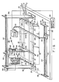
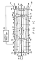
- Fig. 1 shows a film manufacturing apparatus according to a first embodiment of the present invention.
- the apparatus comprises base 10 on which trough 12 having a rectangular opening is placed.
- the inner surface of trough 12 is Teflon-coated and has a water jacket.
- Constant-temperature water 16 can be supplied into trough 12 through water-supply pipe 14 which is connected to the water jacket, and water 16 can be maintained at a predetermined temperature.
- the liquid surface of isothermal water 16 stored in trough 12 forms developing region 18 on which a monomolecular film (to be described later) can be developed.
- a pair of parallel spacers 20 formed of a Teflon tape are arranged above trough 12 to be in contact with the liquid surface of water 16, and extend in the longitudinal direction of the trough.
- Two ends of each spacer 20 are fixed to corresponding rollers 21.
- Rollers 21 are mounted on corresponding guide rods 22, which are fixed to the side walls of trough 12, to be movable in the axial direction of the rods.
- These guide rods 22 extend in a direction perpendicular to spacers 20. Therefore, the pair of spacers 20 are movable in a direction closer to or separate from each other.
- Developing region 18 is partitioned by spacers 20 into an elongated rectangular shape having the same width as the distance between the spacers. By adjusting the distance between spacers 20, the width of developing region 18 is set to be equal to that of substrate 24 serving as a work (to be described later).
- Front barrier 26 of an elongated flat plate is placed on one end portion of trough 12, and is in contact with the liquid surface of water 16. Barrier 26 extends in a direction perpendicular to spacers 20, and its two end portions extend outwardly from trough 12.
- Lead screw 27 is arranged outside trough 12, and extends parallel to spacers 20, i.e., in the longitudinal direction of the trough. Two ends of the screw are rotatably supported by a pair of support plates 28 fixed on base 10. Pulse motor 29 for rotating lead screw 27 is mounted on one supporting plate 28.
- Guide rail 30 is arranged between the pair of supporting plates 28 and extends parallel to lead screw 27. Moving table 31 is engaged with lead screw 27 and guide rail 30 and movable in their axial directions.
- Table 31 is coupled to one end of front barrier 26 through arm 32.
- pulse motor 29 when pulse motor 29 is driven, barrier 26 is moved in the longitudinal direction of trough 12 and compresses a monomolecular film developed in developing region 18 defined between spacers 20, as will be described later.
- Pulse motor 29, lead screw 27, guide rail 30, moving table 31, and arm 32 constitute barrier moving mechanism 25.
- Balance 34 supported on supporting plate 33 is arranged above developing region 18.
- Balance 34 has filter paper 34a dipped in developing region 18 and measures the surface pressure of a monomolecular film developed in the developing region.
- Pulse motor 29 is controlled by barrier drive unit 35 based on the surface pressure measured by balance 34.
- a pair of supporting columns 36 stand upright on base 10 and are located at two sides of trough 12.
- Lead screw 37 and guide rod 38 extend between columns 36 and extend parallel to spacers 20 above developing region 18.
- Horizontal movement pulse motor 39 for rotating lead screw 37 is attached to one supporting column 36.
- Moving table 40 is engaged with lead screw 37 and guide rod 38.
- table 40 is moved in the axial direction of lead screw 37, i.e., horizontal direction.
- Lead screw 37, guide rod 38, pulse motor 39, and moving table 40 constitute horizontal moving mechanism 42 for moving substrate 24 in the horizontal direction.
- Lead screw 41 and guide rod 49 extend downward from moving table 40 in a direction perpendicular to developing region 18.
- Vertical movement pulse motor 43 for rotating lead screw 41 is fixed to table 40.
- Moving table 44 is engaged with lead screw 41 and guide rod 49.
- pulse motor 43 is driven, table 44 is moved in the vertical direction.
- Rectangular substrate 24 serving as a work is supported by table 44 through supporting arm 45.
- Lead screw 41, guide rod 49, pulse motor 43, and moving table 44 constitute vertical moving mechanism 46 for moving substrate 24 upward/downward in a direction perpendicular to developing region 18.
- Elongated planar rear barrier 48 formed of Teflon is supported by moving table 44 through supporting arm 47 and extends in a direction perpendicular to spacers 20.
- Barrier 48 is in contact with the liquid surface of water 16 stored in trough 12 and is also in contact with the rear surface of substrate 24. Barrier 48 is moved in the axial direction of spacers 20 together with moving table 44.
- horizontal and vertical pulse motors 39 and 43 are controlled by horizontal/vertical movement drive unit 50.
- Drive unit 50 stores therein a contact position between substrate 24 and developing region 18.
- Unit 50 has a function of stopping rotation of pulse motor 43 when substrate 24 falls outside the developing region upon vertical movement of substrate 24.
- Substrate 24 is horizontally moved while being moved in a direction perpendicular to developing region 18 (i.e., moved upward or downward) by horizontal and vertical moving mechanisms 42 and 46 and drive unit 50.
- rear barrier 48 is horizontally moved with being in contact with the rear surface of substrate 24. In particular, when substrate 24 separates from developing region 18, rear barrier 48 prevents a monomolecular film from leaking to the liquid surface behind the substrate.
- An LB film is formed as follows using the above-mentioned film manufacturing apparatus.
- unit 35 moves front barrier 26 forward or backward so that the output from balance 34 is kept at predetermined surface pressure ⁇ .
- substrate 24 is dipped in developing region 18.
- substrate 24 is dipped so that its front surface, i.e., build-up surface 24a extends in a direction perpendicular to the longitudinal direction of spacers 20.
- the two side edges of substrate 24 are substantially in contact with corresponding spacers 20.
- substrate 24 is positioned so that its build-up surface 24a extends in a direction perpendicular to developing region 18.
- horizontal and vertical moving mechanisms 42 and 46 are driven by horizontal/vertical movement drive unit 50, so that substrate 24 is moved toward front barrier 26, i.e., ahead of build-up surface 24a while being moved downward through the monomolecular film developed in developing region 18.
- the downward moving speed and horizontal moving speed of substrate 24 are previously determine in accordance with the building-up ratio of the monomolecular film and are input to drive unit 50.
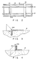
- forced control is performed by drive unit 50 so that the downward moving speed of substrate 24 coincides with the horizontal moving speed. Therefore, as is shown in Fig. 3, substrate 24 is moved obliquely downward through developing region 18. As a result, a monomolecular film of a first layer is built up on build-up surface 24a.
- spacers 20 constitute flow-in regulating means 52 for regulating the flow of molecules during the building-up operation.
- Substrate 24 is moved forward in a direction of compressing the developed monomolecular film during the building-up operation. Therefore, it is possible to compensate a decrease in surface pressure of the monomolecular film near the substrate due to attachment of the monomolecular film to build-up surface 24a of substrate 24, thus the building-up operation can be performed in a state wherein no surface strain occurs in the monomolecular film.
- the building-up operation if the monomolecular film cannot be attached to build-up surface 24a of substrate 24 for some reasons, the developed monomolecular film is excessively compressed by the horizontal movement of the substrate. As a result, molecules may be destroyed. In order to prevent such destruction of molecules, it is preferable that the building-up operation is performed while monitoring the surface pressure of the monomolecular film. When the surface pressure of the monomolecular film is abnormally increased, the building-up operation is stopped.
- Macromolecular films were actually built up as follows using a hydrophobic Si substrate as a work.
- polypeptide or polyimide molecules were developed in developing region 18 partitioned by spacers 20 and front and rear barriers 26 and 48, and were compressed to a surface pressure of 25 dyn/cm by front barrier 26.
- horizontal and vertical moving mechanisms 42 and 46 were driven to repeat the above-mentioned building-up operation.
- a 20-layered monomolecular film was built up on the build-up surface of the Si substrate.
- SEM scanning electron microscope
- the building-up operation was performed by using 5 ⁇ 10 ⁇ 6 M of AlCl3 solution as an aqueous solution in trough 12 and using a stearic acid as the developed molecular. Also in this case, a good built-up film was obtained.
- the pair of spacers 20 are used as flow-in preventing means 52.
- the flow-in preventing means may be arranged as is shown in Fig. 5.
- support shaft 54 is attached to that side wall of trough 12 which is located on the rear surface side of substrate 24, and extends along the widthwise direction of the trough.
- Roller 60 around which Teflon regulating tape 56 constituting flow-in preventing means 52 is wound, is rotatably mounted on support shaft 54.
- Tape 56 has the same width as that of substrate 24.
- support rod 57 having the same length as the width of substrate 24 is arranged to be in contact with the rear surface of the substrate.
- Support rod 57 is supported by moving table 40 through supporting arm 47.
- the free end of regulating tape 56 is fixed to support rod 57, and tape 56 is in contact with the liquid surface of constant-temperature water 16.
- regulating tape 56 When support rod 57 is moved forward together with substrate 24 upon movement of table 40, regulating tape 56 is fed from roller 60 and follows substrate 24. For this reason, during the building-up operation of the monomolecular film, regulating tape 56 is moved forward while burying that region of developing region 18 through which substrate 24 has passed, thereby preventing flow-in of molecules into this region.
- the flow of molecules during the building-up operation can become a parallel flow perpendicular to build-up surface 24a of substrate 24.
- a good built-up film can be formed.
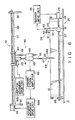
- Figs. 6 to 8 show a film manufacturing apparatus according to a third embodiment of the present invention.
- the same reference numerals as in the first embodiment denote the same parts as in the first embodiment, and a detailed description thereof will be omitted.
- a pair of spacers 20 are formed of Teflon strings in place of Teflon tapes.
- the rear barrier is omitted, and only front barrier 26 is arranged.
- Langmuir-type surface pressure balance 34 is attached to front barrier 26.
- Balance 34 has elongated float 61 floating on the liquid surface of constant-temperature water 16.
- the float is arranged inside front barrier 26 to be parallel thereto.
- Two ends of float 61 are coupled to barrier 26 through thin metal foils 62 of Au or Pt, which serve as leaf springs.
- the float is connected to strain gauge 63 mounted on barrier 26. No monomolecular film is developed on the liquid surface enclosed by front barrier 26, float 61, and metal foils 62.
- float 61 is pressed toward front barrier 26 by surface pressure ⁇ of the monomolecular film developed on developing region 18 partitioned by spacers 20, work 64 (to be described later), and the float, and is stopped when the surface pressure balances the elastic force of metal foils 62.
- the position of float 61 is detected by strain gauge 63 and is converted to an electrical signal.
- Surface pressure ⁇ of the monomolecular film is measured based on the electrical signal, i.e., the position of float 61.
- Surface pressure ⁇ detected by strain gauge 63 is input to barrier drive unit 35, and unit 35 drives pulse motor 29 of barrier moving mechanism 25 in accordance with the detected surface pressure.
- Vertical moving mechanism 46 includes strain gauge 65 of a right-angle displacement type. Work 64 is suspended from gauge 65 through supporting arm 45. When a pressure acts on gauge 65 through arm 45, a strain generates in gauge 65 and is converted to an electrical signal by dynamic strain amplifier 66. Pulse motor 39 of horizontal moving mechanism 42 is driven by horizontal movement drive unit 50a based on the electrical signal from amplifier 66. Note that pulse motor 43 of vertical moving mechanism 46 is driven by vertical movement drive mechanism 50b.
- work 64 is constituted by holder 67 fixed to the lower end of supporting arm 45, and substrate 24 held by the holder.
- Holder 67 is formed in a thin-walled rectangular prism and is fixed to supporting arm 45 so that its front surface 67a is perpendicular to developing region 18 and is perpendicular to the longitudinal direction of spacers 20.
- Front surface 67a is subjected to a surface treatment so that a monomolecular film can be attached thereto.
- Guide grooves 68 extending in the vertical direction are formed in the two vertically extending side surfaces of holder 67, respectively.
- a pair of wires 69 extending in the vertical direction are inserted through holder 67 to be movable in their axial direction.
- Teflon-coated hook 70 is fixed to each wire 69 and extends outwardly from holder 67 through corresponding guide groove 68. Therefore, each hook 70 is vertically movable along corresponding guide groove 68. Substrate 24 is held by a pair of holding members 71 while its rear surface is in tight contact with front surface 67a of holder 67.
- the lower end of work 64 is dipped in developing region 18 after the distance between spacers 20 is adjusted to be substantially equal to the width of holder 67, thereby partitioning the developing region into front and rear regions.
- organic molecules are developed in the front region, i.e., a region defined by spacers 20, work 64, and float 61 (and front barrier 26).
- the monomolecular film is compressed to obtain predetermined surface pressure ⁇ 1 by front barrier 26.
- horizontal movement drive unit 50a drives horizontal moving mechanism 42 so that when the electrical signal is smaller than a predetermined value, work 64 is moved forward; otherwise, moved backward.
- Work 64 is moved vertically (upward or downward) and horizontally by horizontal and vertical moving mechanisms 42 and 46 while the above-mentioned control operation for the pressure difference is continuously performed, thereby building up the monomolecular films on substrate 24.
- the building-up operation can be performed while keeping a constant surface pressure molecular density without applying a surface strain on the monomolecular film in developing region 18.
- a building-up operation was performed as follows. First, 2.0 mM of a cadmium chloride aqueous solution were stored in trough 12, and pentacosa-9,11-diynoic-1-acid (diacetylene molecules) was developed thereon. Thereafter, the developed molecules were compressed to obtain a surface pressure of 25 dyn/cm by front barrier 26. The diacetylene monomolecular film was irradiated with ultraviolet rays by a mercury lamp to be polymerized. A 20-layered monomolecular film was then built up by the above-mentioned building-up operation.
- the obtained film was a good Y-type built-up film having an interlayer distance of 50 ⁇ .
- a rectangular substrate having the same width as that of holder 67 is used as substrate 24.
- a monomolecular film can be built up on a substrate of any shape if the substrate is smaller than front surface 67a of holder 67.
- holder front surface 67a is partially exposed.
- front surface 67a is subjected to a surface treatment to allow attachment of a monomolecular film, a monomolecular film is also built up on the exposed portion of holder front surface 67a as well as build-up surface 24a of substrate 24 during the building-up operation.
- a monomolecular film cannot be attached to holder front surface 67a, the monomolecular film developed on the liquid surface is excessively compressed by the exposed portion of front surface 67a, and thus, molecules may be destroyed. According to this embodiment, however, a monomolecular film can be built up on substrates having various shapes without destroying molecules.
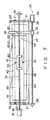
- Figs. 9 and 10 show a film manufacturing apparatus to a fourth embodiment of the present invention.
- the same reference numerals in this embodiment denote the same parts as in the third embodiment described above, and a detailed description thereof will be omitted. That is, portions different from the third embodiment will be explained below.
- rear barrier 48 is arranged on through 12 at the side opposite to front barrier 26 with interposing work 64 between barriers 26 and 28.
- Barrier moving mechanism 72 for moving rear barrier 48 in the longitudinal direction of spacers 20 comprises a pair of support plates 73, lead screw 74, moving table 75, arm 76, and pulse motor 77, as in barrier moving mechanism 25.
- Langmuir-type surface pressure balance 78 is attached to rear barrier 48.
- Balance 78 has the same structure as that of balance 34 on the side of front barrier 26, and includes float 79, metal foils 80, and strain gauge 81 as components.
- Pulse motor 77 of barrier moving mechanism 72 is driven by barrier driving unit 82 based on the surface pressure of a monomolecular film measured by surface pressure balance 78.
- Work 64 is supported by moving table 44 of vertical moving mechanism 46 through supporting arm 45.
- the upper end of arm 45 is attached to table 44 to be pivotal along the longitudinal direction of spacers 20, and is engaged with electromagnetic clamp 83 mounted on table 44.
- clamp 83 When clamp 83 is deenergized, supporting arm 45 can be freely pivoted without friction.
- arm 45 When the clamp is energized, arm 45 is fixed to be perpendicular to developing region 18.
- Work 64 is constituted by holder 67 fixed to the lower end of arm 45 and substrate 24 held by the holder.
- clamp 83 When clamp 83 is energized, build-up surface 24a of the substrate becomes perpendicular to developing region 18.
- a pair of optical sensors 84 are provided at moving table 44, and arm 45 extends between these sensors.
- Horizontal movement drive unit 50a drives horizontal moving mechanism 42 based on the detection signal from sensors 84 so that arm 45 is returned to its vertical position.
- An LB film is formed as follows using the film manufacturing apparatus with the above arrangement.
- the lower end of work 64 is dipped in the liquid surface while the distance between spacers 20 is adjusted to be substantially equal to the width of work 64, thereby partitioning developing region 18 into front and rear regions with respect to the work.
- organic molecules to be built up are developed in the front region, i.e., a region defined by spacers 20, substrate 24, and float 61, (and front barrier 26).
- Molecules with a small viscosity e.g., stearyl alcohol molecules are developed in the rear region, i.e., a region defined by spacers 20, holder 67, and float 79 (and rear barrier 48).
- ⁇ 1 ⁇ 2
- an organic thin film having a uniform structure and free from defects can be formed.
- a stearyl alcohol monomolecular film is built up also on the rear surface of holder 67.
- the monomolecular film of the first layer built up on the rear surface of holder 67 by the upward or downward operation of work 64 is reversibly peeled onto the liquid surface by the next downward or upward operation.
- the surface pressure of the stearyl alcohol monomolecular film is maintained to be a predetermined value by rear barrier 48. Therefore, the stearyl alcohol monomolecular film in the rear region is not decreased regardless of the number of monomolecular films built up on the build-up surface 24a of substrate 24. As a result, molecules need not be replenished in the rear region.
- a 20-layered diacetylene monomolecular film was built up on a substrate following the same procedures as in the fourth embodiment.
- the X-ray diffraction pattern of the obtained built-up film exhibited a high-order diffraction peak, and according to calculations, it was confirmed that the obtained film was a good Y-type built-up film having an interlayer distance of 34 ⁇ .
- a method of shortening a film formation time using the apparatus of the fourth embodiment will be described below. In this case, a description is made using the film formation apparatus of the fourth embodiment. However, as will be described later, in this method, since no compression operation by using the front barrier is performed, the front barrier and the Langmuir-type surface pressure balance attached thereto need not always be arranged.
- organic molecules to be built up are developed in the front region for work 64, and molecules having a small viscosity, e.g., stearyl alcohol molecules are developed in the rear region for the work.
- electromagnetic clamp 83 is deenergized to cause supporting arm 45 to be movable.
- the stearyl alcohol monomolecular film in the rear region is compressed to predetermined surface pressure ⁇ 2 by rear barrier 48.
- front barrier 46 is fixed in position, and the monomolecular film in the front region is not compressed. As a result, the surface pressure behind work 64 is gradually increased.
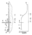
- Fig. 12 illustrates a surface pressure distribution of monomolecular films A and B in this case. As can be seen from Fig. 12, in the front region for work 64, only the surface pressure of monomolecular film B near substrate 24 is increased and balances the surface pressure of stearyl alcohol monomolecular film A.
- the surface pressure of monomolecular film B in a region far from the substrate is not yet increased.
- the building-up operation can be performed in the same manner as in the fourth embodiment. During the building-up operation is performed, a pressure is gradually transmitted to the monomolecular film developed in a region far from substrate 24, and the surface pressure has reached a predetermined value. Therefore, the building-up operation can be continuously performed.
- a compression rate of the monomolecular film by front barrier 26 must be reduced to 0.1 cm/min (1/100 as compared to stearyl alcohol having a small viscosity). For this reason, in order to form a monomolecular film having a length of 50 cm and a surface pressure of 25 dyn/cm on a trough having a width of 2.5 cm, molecules were developed in a developing region having an area twice that of the desired monomolecular film and were compressed, it took 21 hours. Then, when 20 monomolecular film layers were built up on the build-up surface of a substrate having a length of 2.5 cm with the vertical moving speed of the work being 2 mm/min, it took about 5 hours. Therefore, a total time was about 26 hours.
- This embodiment is substantially the same as the above embodiments, except that an operation of inclining a work through a predetermined angle with respect to a developed monomolecular film is performed in addition to the vertical and horizontal movements of the work.
- This embodiment utilizes a nature that even if angle ⁇ of the substrate with respect to the liquid surface is changed, the contact angle has a constant value.
- the film manufacturing apparatus comprises a rotating mechanism for inclining the substrate with respect to the liquid surface in addition to the vertical and horizontal moving mechanisms.
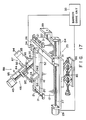
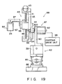
- the film formation apparatus according to the fifth embodiment will be described hereinafter with reference to Figs. 17 and 19.
- the same reference numerals in this embodiment denote the same parts as in the above embodiments, and a detailed description thereof will be omitted.
- Front barrier 26 is arranged on the right end portion of through 12, and barrier moving mechanism 25 for moving the front barrier is arranged aside the trough.
- Barrier moving mechanism 25 has elongated guide plate 84 extending in the longitudinal direction of trough 12, and the two end portions of guide plate 84 are bent at a right angle.
- Lead screw 27 extends between the two end portions of guide plate 84, and pulse motor 29 for rotating the lead screw is mounted on one end portion of the guide plate.
- Moving table 31 is engaged with lead screw 31, and one end of front barrier 26 is fixed to the moving table. Therefore, when pulse motor 29 is driven to move moving table 31, the compression operation by front barrier 26 can be performed.
- Wilhelmy-type surface pressure balance 34 for measuring a surface pressure of a monomolecular film on developing region 18 partitioned by spacers 20 is provided on front barrier 26. Pulse motor 29 of barrier moving mechanism 25 is driven by barrier drive unit 25 in accordance with the surface pressure measured by balance 34. Barrier moving mechanism 25 with the above arrangement is mounted on a platen with an anti-vibration mechanism (not shown) through high-precision jack 85 for adjusting the height of the barrier moving mechanism and magnet base 86.
- building-up mechanism 88 consisting of horizontal moving mechanism 42, vertical moving mechanism 46, and rotating mechanism 87.
- Horizontal moving mechanism 42 has elongated guide plate 89 extending in the longitudinal direction of trough 12, and two end portions of the guide plate are bent at a right angle.
- Lead screw 37 extends between the two end portions of guide plate 89, and pulse motor 39 for rotating the lead screw is mounted on one end portion of the guide plate.
- Moving table 40 is engaged with lead screw 37.
- pulse motor 39 is driven, moving table 40 is moved along the axial direction of the lead screw.
- Mechanism 42 is mounted on the platen with the anti-vibration mechanism through high-precision jack 85 and magnet base 86.
- Rotating mechanism 87 comprises supporting column 90 erected on moving table 40, and pulse motor 92 fixed to the column.
- Motor 92 is arranged so that its rotating shaft 92a is perpendicular to the longitudinal direction of trough 12 and located within a plane parallel to the liquid surface of the trough.
- Rotating shaft 92a projects from column 90 toward trough 12 and is fixed to the intermediate portion of elongated rotary plate 93. Therefore, when pulse motor 92 is driven, rotary plate 93 is rotated within a plane perpendicular to the liquid surface of trough 12.
- Vertical moving mechanism 46 is mounted on one end portion of rotary plate 93, and weight 94 for balancing a weight with mechanism 46 is mounted on the other end portion of plate 93.
- Vertical moving mechanism 46 has elongated guide plate 95 fixed to rotary plate 93.
- the guide plate extends in a direction perpendicular to rotary plate 93 and is located within a plane perpendicular to the liquid surface of trough 12.
- Two end portions of guide plate 95 are bent at a right angle, and lead screw 41 extends between the two end portions.
- Pulse motor 43 for rotating the lead screw is mounted on one end portion of guide plate 95.
- Moving table 44 is engaged with lead screw 41. When pulse motor 43 is driven, moving table 44 is moved along lead screw 41.
- vertical moving mechanism 46 can be rotated by mechanism 87 within a plane perpendicular to the liquid surface of trough 12.
- Compact X-stage 96 and supporting arm 97 are sequentially fixed on moving table 44 of vertical moving mechanism 46, and work 64 is supported by supporting arm 97.
- Work 64 is constituted by substantially U-shaped holder 67 fixed to supporting arm 97 and formed of stainless steel, and substrate 24 held by the holder.
- Work 64 is supported so that build-up surface 24a of substrate 24 is located within a plane parallel to the moving direction of moving table 44 and rotating shaft 92a of pulse motor 92 of rotating mechanism 87.
- Red semiconductor laser oscillator 98 is attached to the free end of rotating shaft 92a of pulse motor 92. The laser oscillator emits a laser beam coinciding with the central axis of rotating shaft 92a.
- work 64 can be moved horizontally and vertically with respect to the liquid surface of trough 12, i.e., developing region 18, and the inclination angle of the work with respect to the developing region can be adjusted.
- the horizontal and vertical moving speeds of work 64 are controlled by horizontal/vertical movement drive unit 50 connected to pulse motors 39 and 43 of mechanisms 42 and 46, and the inclination angle of the work is controlled by rotation drive unit 99 connected to pulse motor 92 of mechanism 87.
- the position of work 64 is adjusted by compact X-stage 96 so that build-up surface 24a of substrate 24 is located on the center of rotation of rotating mechanism 87. This adjustment is performed on the basis of a laser beam emitted from laser oscillator 98. Upon this adjustment, even when work 64 is moved by horizontal and vertical moving mechanisms 42 and 46, the substrate can always be rotated about the boundary between build-up surface 24a of substrate 24 and developing region 18.
- trough 12 is mounted on the platen with the anti-vibration mechanism through a high-precision jack and a magnet base, as barrier moving mechanism 25 and building-up mechanism 88.
- the height of trough 12, barrier moving mechanism 25, and building-up mechanism 88 are adjusted by high-precision jacks 85 so that developing region 18 of trough 12 coincides with the rotational central axis of rotating mechanism 87.
- the position of work 64 is adjusted by compact X-stage 96 so that build-up surface 24a of substrate 24 is located on the rotational central axis of mechanism 87.
- Developing region 18 having the same width as that of work 64 is defined by a pair of spacers 20.
- Work 64 is then rotated by mechanism 87 so that build-up surface 24a of substrate 24 is perpendicular to developing region 18.
- work 64 is moved downward until the lower end of the work is brought into contact with developing region 18, thereby partitioning developing region 18 into front and rear regions with respect to the work.
- a monomolecular film is developed in the front region and is compressed by front barrier 26 until a predetermined surface pressure is obtained.
- moving speed V H of horizontal moving mechanism 42 corresponds to moving speed V W of the boundary between build-up surface 24a and the monomolecular film with respect to the monomolecular film
- moving speed V I of vertical moving mechanism 46 corresponds to moving speed V S of the boundary with respect to build-up surface 24a.
- work 64 is moved upward and forward at the same speed through the monomolecular film, so that a monomolecular film of a second layer is built up on build-up surface 24a of substrate 24.
- the building-up operation can be performed while maintaining a constant surface molecular density without causing a surface strain in the monomolecular film developed in the developing region.
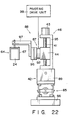
- Figs. 20 to 22 show a film manufacturing apparatus according to still another embodiment comprising a rotating mechanism.
- the same reference numerals denote the same parts as in the fifth embodiment, and a detailed description thereof will be omitted.
- guide plate 95 of vertical moving mechanism 46 is fixed to moving table 40 of horizontal moving mechanism 42 and extends vertically upward from moving table 40.
- Thin-type pulse motor 92 of rotating mechanism 87 is fixed to moving table 44 of vertical moving mechanism 46.
- Motor 92 is arranged so that its rotating shaft (not shown) extends parallel to the liquid surface of trough 12 and in a direction perpendicular to the longitudinal direction of the trough.
- Compact X-stage 96, supporting arm 97, and work 64 are sequentially attached to the rotating shaft of pulse motor 92. As can be seen from Fig. 21, the position of work 64 is adjusted by compact X-stage 96 so that buildup surface 24a of substrate 24 is located on rotational central axis C of pulse motor 92.
- region 18 having the same width as that of work 64 is defined by a pair of spacers 20.
- Work 64 is rotated by rotating mechanism 87 so that build-up surface 24a is perpendicular to developing region 18. Thereafter, the work is moved downward until the lower end of the work is brought into contact with developing region 18, thereby partitioning developing region 18 into front and rear regions with respect to the work. Subsequently, a monomolecular film is developed in the front region and is compressed by front barrier 26 until a predetermined surface pressure is obtained.
- V H the horizontal moving speed of work 64
- V V the vertical moving speed of the work
- inclination angle of substrate 24 ⁇
- V H and V V are calculated so that speeds V W and V S become predetermined values.
- work 64 is moved forward while being moved downward at speeds V H and V V for the downward movement of the substrate, so that a monomolecular film of a first layer is built up on build-up surface 24a of substrate 24.
- Work 64 is then moved upward and forward at speeds V H and V V for upward movement of the substrate through the monomolecular film, thereby building up a monomolecular film of a second layer on build-up surface 24a of substrate 24.
- the building-up operation can be performed while keeping a constant surface molecular density without causing a surface strain in a developed monomolecular film as in the fifth embodiment.
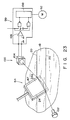
- a curvature of the liquid surface near substrate 24 may be detected by liquid surface detector 100 while work 64 is dipped in developing region 18. Then, inclination angle ⁇ of substrate 24 can be adjusted by rotating mechanism 87 based on the detection signal from detector 100 so that the curve of the liquid surface is eliminated.
- Liquid surface detector 100 comprises laser oscillator 102 and position detecting photodiode 104.
- the photodiode is connected to pulse motor 92 of rotating mechanism 87 through rotating drive unit 99.
- Laser oscillator 102 and photodiode 104 are arranged such that a laser beam is emitted from the laser oscillator on the liquid surface portion near the boundary between build-up surface 24a of substrate 24 and developing region 18, and the beam reflected by the liquid surface becomes incident on the photodiode.
- Photodiode 104 is adjusted so as to output "zero" when it receives a reflection beam from a liquid surface kept flat without being curved.
- reference numerals 106 and 108 denote a zero-cross detector and a motor driver, respectively.
Landscapes
- Engineering & Computer Science (AREA)
- Chemical & Material Sciences (AREA)
- Nanotechnology (AREA)
- Physics & Mathematics (AREA)
- Condensed Matter Physics & Semiconductors (AREA)
- General Physics & Mathematics (AREA)
- Crystallography & Structural Chemistry (AREA)
- Composite Materials (AREA)
- Materials Engineering (AREA)
- Manufacturing & Machinery (AREA)
- Coating Apparatus (AREA)
- Application Of Or Painting With Fluid Materials (AREA)
Abstract
Description
- The present invention relates to a method and apparatus for manufacturing organic thin films having a uniform structure and free from defects, based on the Langmuir-Blodgett technique.
- In recent years, electrical elements utilizing an organic thin film manufactured by the Langmuir-Blodgett technique (to be referred as the LB technique hereinafter) have been developed and studied. In order to apply an organic thin film manufactured by the LB technique to an electrical element, it is important to manufacture a built-up film having a uniform structure and free from defects.
- A conventional film manufacturing apparatus for an organic thin film by the LB technique basically comprises a trough for forming a liquid surface on which a monomolecular film is to be developed, a barrier for compressing the developed monomolecular film, a drive device for the barrier, and a surface pressure balance for detecting a surface pressure of the monomolecular film. The apparatus includes two types of apparatuses, i.e., an apparatus which has one barrier and moves the barrier in one direction, and an apparatus which has two barriers, and moves the barriers in two directions. When organic thin films are manufactured based on the LB technique using the above-mentioned apparatus, organic molecules are dissolved in a developing solution such as chloroform, and the solution is dripped and developed drop by drop on the liquid surface of the trough by an injector. The molecules developed on the liquid surface are compressed by driving the barrier. In this case, the surface pressure of the monomolecular film is monitored by the surface pressure balance as a surface molecular density of the monomolecular film, and the monomolecular film is compressed to obtain predetermined surface pressure π. Then, a substrate is moved perpendicularly to the liquid surface on which the monomolecular film is developed, so that the developed monomolecular film is transferred and built up onto the substrate.
- Since the surface pressure balance for detecting the compressed state of the monomolecular film on the liquid surface, the substrate on which the monomolecular films are built up, and the barrier for compressing the monomolecular film are displaced from each other, the problems occur. More specifically, when the monomolecular films are built up on the substrate, the monomolecular film on the liquid surface is decreased near the substrate, and the surface pressure is also decreased. The conventional film manufacturing apparatus is operated under the assumption that a decrease in surface pressure upon building-up of the monomolecular film is immediately transmitted to the entire monomolecular film and is averaged, and is detected by the surface pressure balance. Thus, the barrier is moved in a compression direction until the monomolecular film recovers the predetermined surface pressure. With this operation, the building-up operation of the monomolecular film is assumed to be performed constantly at the predetermined surface pressure.
- However, molecules which can exhibit properties according to the above assumption are only limited ones such as aliphatic molecules. In contrast to this, since monomolecular films formed of molecules such as dyecontaining molecules and macromolecules exhibit large viscosity, a decrease in surface pressure of the monomolecular film near the substrate is not always immediately transmitted to the surface pressure balance separate from the substrate. The viscosity of the monomolecular film developed on the liquid surface means propagation, relaxation characteristics of a stress (surface pressure) generated when a given surface strain acts on the monomolecular film. More specifically, the viscosity of the monomolecular film delays a propagation time of a change in surface pressure to surface pressure balance. Therefore, when the building-up operation of dye-containing molecules or macromolecules is continued based on the surface pressure detected by the surface pressure balance, the surface density of the monomolecular film near the substrate is continuously decreased. As a result, the density of the monomolecular film built up on the substrate is not constant, and a built-up film having a uniform structure and free from defects cannot be obtained. In order to transfer the monomolecular film on the liquid surface onto the substrate, the surface pressure of the monomolecular film must be equal to or higher than a given value. This value varies depending on types of molecules, hydrophilic and hydrophobic properties and moving directions of the substrate. Therefore, under a given condition, the monomolecular film may be able to be successfully built up but may not be built up if the condition changes.
- Furthermore, when the barrier, substrate, and surface balance are arranged separate from each other, molecules radially flow from a portion around the substrate toward the substrate. For this reason, even if building-up of the monomolecular film is possible, nonuniformity of molecules occur along the boundary between the substrate and the monomolecular film, and a uniform monomolecular film cannot be obtained.
- In order to prevent nonuniformity of the molecular density distribution in the conventional apparatus, the building-up rate of the monomolecular film may be sufficiently decreased so as to eliminate the influence of the viscosity of the monomolecular film, i.e., so as to accurately transmit the surface pressure of the monomolecular film near the substrate to the surface pressure balance. However, with this method, it takes a long period of
time 10 to 1,000 times the existing method, and this method cannot be put into practical applications. - The present invention has been made to solve the above problem, and has as its object to provide a method and apparatus for manufacturing organic thin films having a uniform structure and free from defects within a short period of time.
- In order to achieve the above object, a method according to the present invention comprises the steps of: preparing a liquid surface for forming a developing region on which a monomolecular film of organic molecules can be developed; developing the monomolecular film of the organic molecules in the developing region; compressing the developed monomolecular film to a predetermined surface pressure; and moving a work having a build-up surface through the developed monomolecular film in a direction perpendicular to the monomolecular film while moving the work ahead of the build-up surface in a horizontal direction, thereby building up the monomolecular film on the build-up surface.
- A film formation apparatus according to the present invention comprises: a trough for storing a liquid, the trough having a liquid surface for forming a developing region on which a monomolecular film of organic molecules is developed; compression means for compressing the developed monomolecular film to a predetermined surface pressure; vertical moving means for moving a work in a direction perpendicular to the monomolecular film; horizontal moving means for moving the work ahead of a build-up surface thereof in a horizontal direction; and drive means for driving the vertical and horizontal moving means so that the work is moved in the horizontal direction while being moved upward or downward in the vertical direction through the developed monomolecular film, thereby building up the monomolecular film on the build-up surface.
- According to the present invention, the building-up operation is performed without causing a surface strain due to a decrease in surface pressure of the monomolecular film. The principle of the present invention will be described below.
- According to the present invention, a monomolecular film developed in the developing region is compressed to a predetermined surface pressure by the compression means such as a barrier. However, according to the present invention, since the monomolecular film can be compressed by moving a work in a direction parallel to the monomolecular film, the compression operation of the barrier need not always be performed. After the monomolecular film is compressed to the predetermined surface pressure, the work is moved forward at a predetermined horizontal moving speed while being moved downward through the monomolecular film. Thus, a first monomolecular film can be built up on the build-up surface of the work. Subsequently, the work is moved forward at the predetermined horizontal moving speed while being moved upward through the monomolecular film, thereby building up a second monomolecular film on the build-up surface. Note that when the vertical movement of the work is switched from downward movement to the upward movement and viceversa, the horizontal movement is stopped, and the substrate is moved by a few millimeters in a state wherein the area of the liquid surface is left unchanged. In this case, no monomolecular film is built up on the substrate, and only a meniscal wave formed by the substrate and the liquid surface is changed. The above operation is repeated to form n-layered built-up films on the build-up surface of the work.
- As described above, during the building-up operation of the monomolecular film, the work is moved in a direction parallel to the monomolecular film, so that the work is moved in a direction for compressing the monomolecular film. Therefore, a decrease in surface pressure of the monomolecular film near the work, which is caused when the monomolecular film is transferred to the build-up surface of the work, can be prevented. As a result, no surface strain of the monomolecular film occurs, and a built-up film having a uniform structure and free from defects can be obtained.
- It is preferable that the building-up operation of the monomolecular film is preferably performed in a state wherein the flow of molecules is regulated so that the monomolecular film does not flow into that region of the developing region through which the work has passed. In this case, the flow of molecules relative to the build-up surface of the work during the building-up operation becomes a parallel flow toward the build-up surface. For this reason, neither sparse nor dense regions are generated in the flow of molecules, and a built-up film having a uniform structure can be more easily obtained. According to an embodiment of the present invention, an elongated developing region having the same width as that of the work is defined by a pair of parallel spacers or a pair of parallel strings, and the building-up operation of the monomolecular film is performed while the developing region is partitioned by the work into front and rear regions with respect to the work. It is preferable that the width of the developing region is not fixed but may be desirably changed in accordance with the width of various works.
- The horizontal moving speed of the work is a speed for moving the work forward within the developing region by an area corresponding to the number of molecules of a film built up on the build-up surface per unit time by the vertical movement of the work. More specifically, the horizontal moving speed is determined to maintain the surface molecular density of the monomolecular film ahead of the build-up surface of the work constant, and the determination method includes a forced method and a surface pressure method.
- In the forced method, a build-up ratio of the monomolecular film is preset, and the horizontal moving speed is obtained by multiplying the vertical moving speed with the build-up ratio. The build-up ratio is a ratio of an area of the build-up surface, passing through the monomolecular film when the work is vertically moved, to the number of molecules built up on the build-up surface. For example, when the build-up ratio is 1, the horizontal moving speed of the work is equal to the upward/downward speed, and the work is moved in an oblique direction of 45 degrees. In order to avoid trouble that a monomolecular film cannot be built up on the build-up surface of the work and the surface pressure of the monomolecular film is abnormally increased, the building-up operation is preferably performed while monitoring the surface pressure of the monomolecular film using a surface pressure balance.
- In the surface pressure method, a pressure acting on the work is detected, and the horizontal moving speed of the work is determined based on the detected pressure. For example, when an elongated developing region having the same width as the work is defined and is partitioned by the work into front and rear regions with respect to the work, as described above, if a surface pressure of the monomolecular film developed in the front region of the work is given as π1 and that of the monomolecular film developed on the rear region is given as π2, the work receives a pressure difference of Δπ = π1 - π2 from the front region toward the rear region. Therefore, if a pressure difference detecting section for detecting Δπ is coupled to the work and the horizontal moving speed of the work is controlled so that Δπ becomes a predetermined value, an ideal building-up operation can be performed with any build-up ratio.
- When the surface pressure method is used, a film can be formed in various modes, and pressure differences to be detected are as follows. For example, if a monomolecular film to be built up is developed and compressed on the front region ahead of the work and no molecules are developed in the rear region (π2 = 0), then Δπ =π1. If a monomolecular film to be built up is developed in the front region and a monomolecular film having a low viscosity is developed in the rear region and compressed to yield π2 = π1, then Δπ = 0. Note that in the latter case, if the work is arranged to be freely movable forward/backward along the molecule developing region to a position yielding Δπ = 0, the absolute value of the pressure difference acting on the work need not always be detected.
- According to the present invention, the work can have a function of detecting a surface pressure of the developed monomolecular film and a function of compressing the monomolecular film. Therefore, the compression operation of the monomolecular film can be performed while controlling a molecular density near the work. For this reason, even when the entire developed monomolecular film is not compressed to a predetermined surface pressure, the building-up operation can be started as soon as only the surface pressure near the work reaches a desired value. Therefore, it is possible to build up molecules which have a large viscosity and may often be difficult to obtain a compressed film having a constant surface pressure, within a short period of time.
- This invention can be more fully understood from the following detailed description when taken in conjunction with the accompanying drawings, in which:
- Figs. 1 to 4 show a film manufacturing apparatus according to a first embodiment of the present invention, in which Fig. 1 is a perspective view showing the overall apparatus, Fig. 2 is a plan view schematically showing the apparatus, and Figs. 3 and 4 are views schematically showing building-up processes of a monomolecular film;
- Fig. 5 is a perspective view showing a film manufacturing apparatus according to a second embodiment of the present invention;
- Figs. 6 to 8 show a film manufacturing apparatus according to a third embodiment of the present invention, in which Fig. 6 is a side view of the apparatus, Fig. 7 is a plan view of the apparatus, and Fig. 8 is a perspective view of a holder;
- Figs. 9 to 12 show a film manufacturing apparatus according to a fourth embodiment of the present invention, in which Fig. 9 is a side view of the apparatus, Fig. 10 is a plan view of the apparatus, Fig. 11 is a view schematically showing a compressed state of a developed monomolecular film, and Fig. 12 is a graph showing the compressed state;
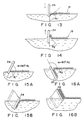
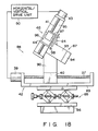
- Figs. 13 to 19 show a fifth embodiment of the present invention, in which Figs. 13 and 14 are side views showing contact angles between a substrate and a liquid surface during upward and downward movements of the substrate, respectively, Figs. 15A and 15B are side views schematically showing building-up processes during downward movement of the substrate, respectively, Figs. 16A and 16B are side views schematically showing building-up processes during upward movement of the substrate, respectively, Fig. 17 is a perspective view showing a film manufacturing apparatus according to the fifth embodiment, and Figs. 18 and 19 are a side view and a front view of a building-up mechanism;
- Figs. 20 to 22 show a film manufacturing apparatus according to a sixth embodiment of the present invention, in which Fig. 20 is a perspective view showing the overall apparatus, and Figs. 21 and 22 are a side view and a front view of a building-up mechanism; and
- Fig. 23 is a view schematically showing a modification of a position detecting mechanism and a rotary driving mechanism.
- Embodiments of the present invention will now be described with reference to the accompanying drawings.
- Fig. 1 shows a film manufacturing apparatus according to a first embodiment of the present invention. The apparatus comprises
base 10 on whichtrough 12 having a rectangular opening is placed. The inner surface oftrough 12 is Teflon-coated and has a water jacket. Constant-temperature water 16 can be supplied intotrough 12 through water-supply pipe 14 which is connected to the water jacket, andwater 16 can be maintained at a predetermined temperature. The liquid surface ofisothermal water 16 stored intrough 12forms developing region 18 on which a monomolecular film (to be described later) can be developed. A pair ofparallel spacers 20 formed of a Teflon tape are arranged abovetrough 12 to be in contact with the liquid surface ofwater 16, and extend in the longitudinal direction of the trough. Two ends of eachspacer 20 are fixed to correspondingrollers 21.Rollers 21 are mounted oncorresponding guide rods 22, which are fixed to the side walls oftrough 12, to be movable in the axial direction of the rods. These guiderods 22 extend in a direction perpendicular tospacers 20. Therefore, the pair ofspacers 20 are movable in a direction closer to or separate from each other. Developingregion 18 is partitioned byspacers 20 into an elongated rectangular shape having the same width as the distance between the spacers. By adjusting the distance betweenspacers 20, the width of developingregion 18 is set to be equal to that ofsubstrate 24 serving as a work (to be described later). -
Front barrier 26 of an elongated flat plate is placed on one end portion oftrough 12, and is in contact with the liquid surface ofwater 16.Barrier 26 extends in a direction perpendicular tospacers 20, and its two end portions extend outwardly fromtrough 12. Leadscrew 27 is arranged outsidetrough 12, and extends parallel to spacers 20, i.e., in the longitudinal direction of the trough. Two ends of the screw are rotatably supported by a pair ofsupport plates 28 fixed onbase 10.Pulse motor 29 for rotatinglead screw 27 is mounted on one supportingplate 28.Guide rail 30 is arranged between the pair of supportingplates 28 and extends parallel to leadscrew 27. Moving table 31 is engaged withlead screw 27 andguide rail 30 and movable in their axial directions. Table 31 is coupled to one end offront barrier 26 througharm 32. Thus, whenpulse motor 29 is driven,barrier 26 is moved in the longitudinal direction oftrough 12 and compresses a monomolecular film developed in developingregion 18 defined betweenspacers 20, as will be described later.Pulse motor 29,lead screw 27,guide rail 30, moving table 31, andarm 32 constitutebarrier moving mechanism 25. -
Surface pressure balance 34 supported on supportingplate 33 is arranged above developingregion 18.Balance 34 has filter paper 34a dipped in developingregion 18 and measures the surface pressure of a monomolecular film developed in the developing region.Pulse motor 29 is controlled bybarrier drive unit 35 based on the surface pressure measured bybalance 34. - A pair of supporting
columns 36 stand upright onbase 10 and are located at two sides oftrough 12. Leadscrew 37 and guiderod 38 extend betweencolumns 36 and extend parallel to spacers 20 above developingregion 18. Horizontalmovement pulse motor 39 for rotatinglead screw 37 is attached to one supportingcolumn 36. Moving table 40 is engaged withlead screw 37 and guiderod 38. Thus, whenmotor 39 is driven, table 40 is moved in the axial direction oflead screw 37, i.e., horizontal direction. Leadscrew 37,guide rod 38,pulse motor 39, and moving table 40 constitute horizontal movingmechanism 42 for movingsubstrate 24 in the horizontal direction. - Lead
screw 41 and guiderod 49 extend downward from moving table 40 in a direction perpendicular to developingregion 18. Verticalmovement pulse motor 43 for rotatinglead screw 41 is fixed to table 40. Moving table 44 is engaged withlead screw 41 and guiderod 49. Whenpulse motor 43 is driven, table 44 is moved in the vertical direction.Rectangular substrate 24 serving as a work is supported by table 44 through supportingarm 45. Leadscrew 41,guide rod 49,pulse motor 43, and moving table 44 constitute vertical movingmechanism 46 for movingsubstrate 24 upward/downward in a direction perpendicular to developingregion 18. - Elongated planar
rear barrier 48 formed of Teflon is supported by moving table 44 through supportingarm 47 and extends in a direction perpendicular tospacers 20.Barrier 48 is in contact with the liquid surface ofwater 16 stored intrough 12 and is also in contact with the rear surface ofsubstrate 24.Barrier 48 is moved in the axial direction ofspacers 20 together with moving table 44. - The operations of horizontal and
vertical pulse motors movement drive unit 50.Drive unit 50 stores therein a contact position betweensubstrate 24 and developingregion 18.Unit 50 has a function of stopping rotation ofpulse motor 43 whensubstrate 24 falls outside the developing region upon vertical movement ofsubstrate 24.Substrate 24 is horizontally moved while being moved in a direction perpendicular to developing region 18 (i.e., moved upward or downward) by horizontal and vertical movingmechanisms unit 50. Simultaneously,rear barrier 48 is horizontally moved with being in contact with the rear surface ofsubstrate 24. In particular, whensubstrate 24 separates from developingregion 18,rear barrier 48 prevents a monomolecular film from leaking to the liquid surface behind the substrate. - An LB film is formed as follows using the above-mentioned film manufacturing apparatus.
- The distance between
spacers 20 is adjusted whilesubstrate 24 is not dipped inwater 16, thereby defining developingregion 18 having the same width as that ofsubstrate 24. In this state, organic molecules are developed in the region partitioned by the pair ofspacers 20, and front andrear barriers front barrier 26 is moved towardrear barrier 48 to compress a monomolecular film of organic molecules. In this case, when the output fromsurface pressure balance 34 indicates a value smaller than predetermined surface pressure π, driveunit 35 movesfront barrier 26 forward in the compressing direction at a constant speed. When the output frombalance 34 coincides with predetermined surface pressure π,unit 35 stops the forward movement of the front barrier. Thereafter,unit 35 movesfront barrier 26 forward or backward so that the output frombalance 34 is kept at predetermined surface pressure π. Then,substrate 24 is dipped in developingregion 18. At this time, as can be seen from Fig. 2,substrate 24 is dipped so that its front surface, i.e., build-upsurface 24a extends in a direction perpendicular to the longitudinal direction ofspacers 20. For this reason, the two side edges ofsubstrate 24 are substantially in contact with correspondingspacers 20. In this embodiment,substrate 24 is positioned so that its build-upsurface 24a extends in a direction perpendicular to developingregion 18. - In this state, horizontal and vertical moving
mechanisms movement drive unit 50, so thatsubstrate 24 is moved towardfront barrier 26, i.e., ahead of build-upsurface 24a while being moved downward through the monomolecular film developed in developingregion 18. In this case, the downward moving speed and horizontal moving speed ofsubstrate 24 are previously determine in accordance with the building-up ratio of the monomolecular film and are input to driveunit 50. In this embodiment, forced control is performed bydrive unit 50 so that the downward moving speed ofsubstrate 24 coincides with the horizontal moving speed. Therefore, as is shown in Fig. 3,substrate 24 is moved obliquely downward through developingregion 18. As a result, a monomolecular film of a first layer is built up on build-upsurface 24a. Aftersubstrate 24 is dipped inwater 16 by a predetermined depth, the operations of horizontal and vertical movingmechanisms mechanisms drive unit 50, so thatsubstrate 24 is moved ahead of build-upsurface 24a while being moved upward. Therefore, as is shown in Fig. 4,substrate 24 is moved obliquely upward through developingregion 18, and thus, a monomolecular film of a second layer is built up on build-upsurface 24a. The above mentioned building-up operation is repeated, so that a required number of monomolecular films can be built up on build-upsurface 24a. - As described above, since developing
region 18 is partitioned byspacers 20 to have substantially the same width as that ofsubstrate 24, the molecules can be prevented byspacers 20 from flowing behindsubstrate 24, i.e., flowing into that region through whichsubstrate 24 has already passed. Therefore, as is indicated by arrows in Fig. 2, the flow of developed molecules during the building-up operation becomes a parallel flow in a direction perpendicular to build-upsurface 24a ofsubstrate 24. As a result, the flow of molecules does not include a sparse or dense region. In this manner, spacers 20 constitute flow-in regulating means 52 for regulating the flow of molecules during the building-up operation.Substrate 24 is moved forward in a direction of compressing the developed monomolecular film during the building-up operation. Therefore, it is possible to compensate a decrease in surface pressure of the monomolecular film near the substrate due to attachment of the monomolecular film to build-upsurface 24a ofsubstrate 24, thus the building-up operation can be performed in a state wherein no surface strain occurs in the monomolecular film. - During the building-up operation, if the monomolecular film cannot be attached to build-up
surface 24a ofsubstrate 24 for some reasons, the developed monomolecular film is excessively compressed by the horizontal movement of the substrate. As a result, molecules may be destroyed. In order to prevent such destruction of molecules, it is preferable that the building-up operation is performed while monitoring the surface pressure of the monomolecular film. When the surface pressure of the monomolecular film is abnormally increased, the building-up operation is stopped. - Macromolecular films were actually built up as follows using a hydrophobic Si substrate as a work. First, polypeptide or polyimide molecules were developed in developing
region 18 partitioned byspacers 20 and front andrear barriers front barrier 26. Thereafter, horizontal and vertical movingmechanisms - In another practice, the building-up operation was performed by using 5 × 10⁻⁶ M of AℓCℓ₃ solution as an aqueous solution in
trough 12 and using a stearic acid as the developed molecular. Also in this case, a good built-up film was obtained. - An building-up operation of a monomolecular film was tried by a conventional film manufacturing apparatus such that the upward/downward movement of the substrate was synchronous with the compression operation of the film. No monomolecular film could be built up on the substrate at all.
- In the first embodiment, the pair of
spacers 20 are used as flow-in preventingmeans 52. However, the flow-in preventing means may be arranged as is shown in Fig. 5. - According to this, embodiment,
support shaft 54 is attached to that side wall oftrough 12 which is located on the rear surface side ofsubstrate 24, and extends along the widthwise direction of the trough.Roller 60, around whichTeflon regulating tape 56 constituting flow-in preventingmeans 52 is wound, is rotatably mounted onsupport shaft 54.Tape 56 has the same width as that ofsubstrate 24. In place of the rear barrier,support rod 57 having the same length as the width ofsubstrate 24 is arranged to be in contact with the rear surface of the substrate.Support rod 57 is supported by moving table 40 through supportingarm 47. The free end of regulatingtape 56 is fixed to supportrod 57, andtape 56 is in contact with the liquid surface of constant-temperature water 16. Whensupport rod 57 is moved forward together withsubstrate 24 upon movement of table 40, regulatingtape 56 is fed fromroller 60 and followssubstrate 24. For this reason, during the building-up operation of the monomolecular film, regulatingtape 56 is moved forward while burying that region of developingregion 18 through whichsubstrate 24 has passed, thereby preventing flow-in of molecules into this region. - Also in the second embodiment with the above arrangement, the flow of molecules during the building-up operation can become a parallel flow perpendicular to build-up
surface 24a ofsubstrate 24. As a result, a good built-up film can be formed. - Figs. 6 to 8 show a film manufacturing apparatus according to a third embodiment of the present invention. In this embodiment, the same reference numerals as in the first embodiment denote the same parts as in the first embodiment, and a detailed description thereof will be omitted.
- In the third embodiment, a pair of
spacers 20 are formed of Teflon strings in place of Teflon tapes. The rear barrier is omitted, and onlyfront barrier 26 is arranged. Langmuir-typesurface pressure balance 34 is attached tofront barrier 26.Balance 34 has elongatedfloat 61 floating on the liquid surface of constant-temperature water 16. The float is arranged insidefront barrier 26 to be parallel thereto. Two ends offloat 61 are coupled tobarrier 26 through thin metal foils 62 of Au or Pt, which serve as leaf springs. The float is connected tostrain gauge 63 mounted onbarrier 26. No monomolecular film is developed on the liquid surface enclosed byfront barrier 26,float 61, and metal foils 62. For this reason, float 61 is pressed towardfront barrier 26 by surface pressure π of the monomolecular film developed on developingregion 18 partitioned byspacers 20, work 64 (to be described later), and the float, and is stopped when the surface pressure balances the elastic force of metal foils 62. The position offloat 61 is detected bystrain gauge 63 and is converted to an electrical signal. Surface pressure π of the monomolecular film is measured based on the electrical signal, i.e., the position offloat 61. Surface pressure π detected bystrain gauge 63 is input tobarrier drive unit 35, andunit 35 drives pulsemotor 29 ofbarrier moving mechanism 25 in accordance with the detected surface pressure. - Vertical moving
mechanism 46 includesstrain gauge 65 of a right-angle displacement type.Work 64 is suspended fromgauge 65 through supportingarm 45. When a pressure acts ongauge 65 througharm 45, a strain generates ingauge 65 and is converted to an electrical signal bydynamic strain amplifier 66.Pulse motor 39 of horizontal movingmechanism 42 is driven by horizontalmovement drive unit 50a based on the electrical signal fromamplifier 66. Note thatpulse motor 43 of vertical movingmechanism 46 is driven by verticalmovement drive mechanism 50b. - As is shown in Fig. 8, in the third embodiment,
work 64 is constituted byholder 67 fixed to the lower end of supportingarm 45, andsubstrate 24 held by the holder.Holder 67 is formed in a thin-walled rectangular prism and is fixed to supportingarm 45 so that itsfront surface 67a is perpendicular to developingregion 18 and is perpendicular to the longitudinal direction ofspacers 20.Front surface 67a is subjected to a surface treatment so that a monomolecular film can be attached thereto.Guide grooves 68 extending in the vertical direction are formed in the two vertically extending side surfaces ofholder 67, respectively. A pair ofwires 69 extending in the vertical direction are inserted throughholder 67 to be movable in their axial direction. Teflon-coatedhook 70 is fixed to eachwire 69 and extends outwardly fromholder 67 throughcorresponding guide groove 68. Therefore, eachhook 70 is vertically movable alongcorresponding guide groove 68.Substrate 24 is held by a pair of holdingmembers 71 while its rear surface is in tight contact withfront surface 67a ofholder 67. - As is shown in Fig. 8, when
work 64 is moved downward by vertical movingmechanism 46 in a state wherein the distance betweenspacers 20 is adjusted to be substantially equal to the width ofholder 67, the pair ofhooks 70 are hooked on correspondingspacers 20 from the upper direction. During horizontal movement ofwork 64, hooks 70 slide onspacers 20 with a little friction. Developingregion 18 defined betweenspacers 20 is partitioned into front and rear regions bywork 64. The distance betweenspacers 20 is adjusted to be slightly larger than the width of holder 67 (by, e.g., about 0.5 mm). - A method of forming an LB film using the film manufacturing apparatus with the above arrangement will be described.
- First, the lower end of
work 64 is dipped in developingregion 18 after the distance betweenspacers 20 is adjusted to be substantially equal to the width ofholder 67, thereby partitioning the developing region into front and rear regions. In this state, organic molecules are developed in the front region, i.e., a region defined by spacers 20,work 64, and float 61 (and front barrier 26). Then, the monomolecular film is compressed to obtain predetermined surface pressure π1 byfront barrier 26. Note that since the rear region is a pure water surface, its surface pressure is π2 = 0. In this case, a strain is generated instrain gauge 50 by pressure difference Δπ = π1 acting onwork 64, and is converted into an electrical signal bydynamic strain amplifier 66. Then, horizontalmovement drive unit 50a drives horizontal movingmechanism 42 so that when the electrical signal is smaller than a predetermined value,work 64 is moved forward; otherwise, moved backward. - When
work 64 is moved downward in a small range, the monomolecular film in developingregion 18 is built up on build-upsurface 24a ofsubstrate 24. In this case, since the molecules ahead ofsubstrate 24 have a large viscosity, a small decrease in surface pressure of the monomolecular film near the substrate is not transmitted to surfacepressure balance 34 attached tofront barrier 26. However, the decrease in surface pressure is detected bystrain gauge 34 since a pressure difference acting onwork 64 changes. Therefore, work 64 is moved forward to compress the monomolecular film until pressure difference Δπ corresponds to π1.Work 64 is moved vertically (upward or downward) and horizontally by horizontal and vertical movingmechanisms substrate 24. With the above operation, the building-up operation can be performed while keeping a constant surface pressure molecular density without applying a surface strain on the monomolecular film in developingregion 18. - In practice, a building-up operation was performed as follows. First, 2.0 mM of a cadmium chloride aqueous solution were stored in
trough 12, and pentacosa-9,11-diynoic-1-acid (diacetylene molecules) was developed thereon. Thereafter, the developed molecules were compressed to obtain a surface pressure of 25 dyn/cm byfront barrier 26. The diacetylene monomolecular film was irradiated with ultraviolet rays by a mercury lamp to be polymerized. A 20-layered monomolecular film was then built up by the above-mentioned building-up operation. An X-ray diffraction pattern of the obtained monomolecular film exhibited a high-order diffraction peak. According to calculations, it was confirmed that the obtained film was a good Y-type built-up film having an interlayer distance of 34 Å. - Similarly, in another case wherein the building-up operation was performed while a stearate was developed on the liquid surface of 5 × 10⁻⁶ M of AℓCℓ₃ solution, the obtained film was a good Y-type built-up film having an interlayer distance of 50 Å.
- In contrast to this, a vertical building-up method was practiced at a constant position without horizontally moving a substrate in synchronism with the compression operation by the barrier, using a conventional film manufacturing apparatus. In this case, no polymerized monomolecular film of diacetylene molecules could be built up at all.
- In the third embodiment, a rectangular substrate having the same width as that of
holder 67 is used assubstrate 24. However, a monomolecular film can be built up on a substrate of any shape if the substrate is smaller thanfront surface 67a ofholder 67. For example, if a triangular substrate is used, holderfront surface 67a is partially exposed. As described above, sincefront surface 67a is subjected to a surface treatment to allow attachment of a monomolecular film, a monomolecular film is also built up on the exposed portion of holderfront surface 67a as well as build-upsurface 24a ofsubstrate 24 during the building-up operation. If a monomolecular film cannot be attached to holderfront surface 67a, the monomolecular film developed on the liquid surface is excessively compressed by the exposed portion offront surface 67a, and thus, molecules may be destroyed. According to this embodiment, however, a monomolecular film can be built up on substrates having various shapes without destroying molecules. - Figs. 9 and 10 show a film manufacturing apparatus to a fourth embodiment of the present invention. The same reference numerals in this embodiment denote the same parts as in the third embodiment described above, and a detailed description thereof will be omitted. That is, portions different from the third embodiment will be explained below.
- According to the fourth embodiment,
rear barrier 48 is arranged on through 12 at the side opposite tofront barrier 26 with interposingwork 64 betweenbarriers Barrier moving mechanism 72 for movingrear barrier 48 in the longitudinal direction ofspacers 20 comprises a pair ofsupport plates 73,lead screw 74, moving table 75,arm 76, andpulse motor 77, as inbarrier moving mechanism 25. - Langmuir-type
surface pressure balance 78 is attached torear barrier 48.Balance 78 has the same structure as that ofbalance 34 on the side offront barrier 26, and includesfloat 79, metal foils 80, andstrain gauge 81 as components.Pulse motor 77 ofbarrier moving mechanism 72 is driven bybarrier driving unit 82 based on the surface pressure of a monomolecular film measured bysurface pressure balance 78. -
Work 64 is supported by moving table 44 of vertical movingmechanism 46 through supportingarm 45. The upper end ofarm 45 is attached to table 44 to be pivotal along the longitudinal direction ofspacers 20, and is engaged withelectromagnetic clamp 83 mounted on table 44. Whenclamp 83 is deenergized, supportingarm 45 can be freely pivoted without friction. When the clamp is energized,arm 45 is fixed to be perpendicular to developingregion 18.Work 64 is constituted byholder 67 fixed to the lower end ofarm 45 andsubstrate 24 held by the holder. Whenclamp 83 is energized, build-upsurface 24a of the substrate becomes perpendicular to developingregion 18. A pair ofoptical sensors 84 are provided at moving table 44, andarm 45 extends between these sensors. Whenarm 45 is pivoted and is displaced from its vertical position, this displacement is detected byoptical sensors 84. Horizontalmovement drive unit 50a drives horizontal movingmechanism 42 based on the detection signal fromsensors 84 so thatarm 45 is returned to its vertical position. - An LB film is formed as follows using the film manufacturing apparatus with the above arrangement.
- First, the lower end of
work 64 is dipped in the liquid surface while the distance betweenspacers 20 is adjusted to be substantially equal to the width ofwork 64, thereby partitioning developingregion 18 into front and rear regions with respect to the work. Subsequently, organic molecules to be built up are developed in the front region, i.e., a region defined by spacers 20,substrate 24, and float 61, (and front barrier 26). Molecules with a small viscosity, e.g., stearyl alcohol molecules are developed in the rear region, i.e., a region defined by spacers 20,holder 67, and float 79 (and rear barrier 48).Electromagnetic clamp 83 is then energized to fix supportingarm 45 in the vertical position. In this state, the monomolecular films developed in the front and rear regions are compressed by front andrear barriers clamp 83 is deenergized in this condition, since the surface pressures ahead of and behindwork 64 are equal to each other, work 64 is stopped in position. - When
work 64 is moved downward in a small range, the monomolecular film in the front region is built up on build-upsurface 24a ofsubstrate 24. At this time, since the molecules in the front region have a large viscosity, a small decrease in surface pressure nearsubstrate 24 is not immediately transmitted to surfacepressure balance 34 attached tofront barrier 26. In contrast to this, for the stearyl alcohol monomolecular film in the rear region, a decrease in surface pressure nearholder 67 is instantaneously transmitted to surfacepressure balance 78. Thus,rear barrier 48 performs the compression operation, and the surface pressure of the monomolecular film developed in the rear region can be maintained to be a predetermined value. As a result, the surface pressure ahead ofwork 64 becomes lower than the rear surface pressure, and the work is slightly pushed forward and is stopped when the front and rear surface pressures ofwork 4 are balanced. In this state, supportingarm 45 is inclined forward together withwork 64, and its inclination is detected byoptical sensors 84. Thus, horizontalmovement driving unit 50a drivespulse motor 39 of horizontal movingmechanism 42 based on the signals fromoptical sensors 84, so as to move moving table 40 until the inclination of supportingarm 45 becomes zero. Vertical movingmechanism 46 is driven by verticalmovement drive unit 50b while continuously performing the above-mentioned control operation. Thus, work 64 is moved vertically (upward or downward) and horizontally, thereby building up monomolecular films. With the above operation, monomolecular films can be built up on build-upsurface 24a ofsubstrate 24 while maintaining a predetermined surface pressure molecular density without causing a surface strain in the monomolecular film developed in developingregion 18. - In this embodiment, an organic thin film having a uniform structure and free from defects can be formed.
- After the above-mentioned operation, a stearyl alcohol monomolecular film is built up also on the rear surface of
holder 67. The monomolecular film of the first layer built up on the rear surface ofholder 67 by the upward or downward operation ofwork 64 is reversibly peeled onto the liquid surface by the next downward or upward operation. During this interval, the surface pressure of the stearyl alcohol monomolecular film is maintained to be a predetermined value byrear barrier 48. Therefore, the stearyl alcohol monomolecular film in the rear region is not decreased regardless of the number of monomolecular films built up on the build-upsurface 24a ofsubstrate 24. As a result, molecules need not be replenished in the rear region. - In practice, a 20-layered diacetylene monomolecular film was built up on a substrate following the same procedures as in the fourth embodiment. The X-ray diffraction pattern of the obtained built-up film exhibited a high-order diffraction peak, and according to calculations, it was confirmed that the obtained film was a good Y-type built-up film having an interlayer distance of 34 Å.
- Also in the case wherein an aluminum stearate was used as the developed molecules, a good built-up film was obtained.
- A method of shortening a film formation time using the apparatus of the fourth embodiment will be described below. In this case, a description is made using the film formation apparatus of the fourth embodiment. However, as will be described later, in this method, since no compression operation by using the front barrier is performed, the front barrier and the Langmuir-type surface pressure balance attached thereto need not always be arranged.
- In the same manner as in the above embodiment, first, organic molecules to be built up are developed in the front region for
work 64, and molecules having a small viscosity, e.g., stearyl alcohol molecules are developed in the rear region for the work. Then,electromagnetic clamp 83 is deenergized to cause supportingarm 45 to be movable. In this state, the stearyl alcohol monomolecular film in the rear region is compressed to predetermined surface pressure π2 byrear barrier 48. Meanwhile,front barrier 46 is fixed in position, and the monomolecular film in the front region is not compressed. As a result, the surface pressure behindwork 64 is gradually increased. Since the surface pressure ahead ofwork 64 is almost 0,work 64 is pushed forward, thus compressing the molecules with a large viscosity. More specifically, as is shown in Fig. 11, whenrear barrier 48 compresses stearyl alcohol monomolecular film A, monomolecular film A pusheswork 64, and work 64 compresses front monomolecular film B having a large viscosity. Fig. 12 illustrates a surface pressure distribution of monomolecular films A and B in this case. As can be seen from Fig. 12, in the front region forwork 64, only the surface pressure of monomolecular film B nearsubstrate 24 is increased and balances the surface pressure of stearyl alcohol monomolecular film A. However, the surface pressure of monomolecular film B in a region far from the substrate is not yet increased. In this manner, in the region nearsubstrate 24, since the surface pressure of the monomolecular film has reached a predetermined value, the building-up operation can be performed in the same manner as in the fourth embodiment. During the building-up operation is performed, a pressure is gradually transmitted to the monomolecular film developed in a region far fromsubstrate 24, and the surface pressure has reached a predetermined value. Therefore, the building-up operation can be continuously performed. - In practice, poly(γ-benzyl-L-glutamate) (molecular weight = 100,000) was used as molecules with a large viscosity, and 20-layered monomolecular films were built up on a substrate by using the method shown in the fourth embodiment and the above-mentioned method of shortening the film formation time, respectively. Then, times required for the building-up operations were compared.
- In the former method, a compression rate of the monomolecular film by
front barrier 26 must be reduced to 0.1 cm/min (1/100 as compared to stearyl alcohol having a small viscosity). For this reason, in order to form a monomolecular film having a length of 50 cm and a surface pressure of 25 dyn/cm on a trough having a width of 2.5 cm, molecules were developed in a developing region having an area twice that of the desired monomolecular film and were compressed, it took 21 hours. Then, when 20 monomolecular film layers were built up on the build-up surface of a substrate having a length of 2.5 cm with the vertical moving speed of the work being 2 mm/min, it took about 5 hours. Therefore, a total time was about 26 hours. - In contrast to this, when the building-up operation was conducted while the work itself compressed the monomolecular film according to the latter method, a time required for building up 20 monomolecular film layers was 7 hours, and the operation could be completed within a time 1/4 the former method.
- A fifth embodiment of the present invention will be described below.
- This embodiment is substantially the same as the above embodiments, except that an operation of inclining a work through a predetermined angle with respect to a developed monomolecular film is performed in addition to the vertical and horizontal movements of the work.
- As shown in Fig. 13, when
substrate 24 is moved downward through the developed monomolecular film, a meniscus is formed at the boundary region between the substrate surface and the liquid surface, and the liquid surface is curved downward. Similarly, whensubstrate 24 is moved upward through the monomolecular film, the liquid surface is curved upward, as is shown in Fig. 14, at the boundary region between the substrate surface and the liquid surface. Such a curve may cause a surface strain in the monomolecular film developed on the liquid surface. Angle ϑ defined by the surface ofsubstrate 24 and the liquid surface is called a contact angle. As can be seen from Figs. 13 and 14, the contact angles (ϑ1, ϑ2) differ when the substrate is moved downward and upward. For this reason, when the movement of the substrate is switched from downward to upward and vice-versa, only the meniscal wave is changed, and a monomolecular film cannot be attached to the substrate for a given period of time. During this period, when the substrate vertically held with respect to the monomolecular film is horizontally moved, the monomolecular film may be excessively compressed. - This embodiment utilizes a nature that even if angle α of the substrate with respect to the liquid surface is changed, the contact angle has a constant value. In this embodiment, the building-up operation is performed in a state wherein the substrate is inclined at angle α = 180° - ϑ with respect to the liquid surface. More specifically, as is shown in Figs. 15A and 15B, the building-up operation of the monomolecular film is performed by moving the substrate downward and forward while
substrate 24 is inclined at angle α = 180° - ϑ1 with respect to the liquid surface so that the curve of the liquid surface near the substrate is eliminated, thereby keeping the liquid surface flat. Further, as is shown in Figs. 16A and 16B,substrate 24 is inclined at angle α = 180° - ϑ2 with respect to the liquid surface, and the substrate is moved upward and forward in this state, thereby building up the monomolecular film. Since contact angles during the upward and downward movement of the substrate are different from each other, these contact angles were measured by tests, and inclination angle α of the substrate with respect to the liquid surface is determined in accordance with the test values. - According to this embodiment, the film manufacturing apparatus comprises a rotating mechanism for inclining the substrate with respect to the liquid surface in addition to the vertical and horizontal moving mechanisms. The film formation apparatus according to the fifth embodiment will be described hereinafter with reference to Figs. 17 and 19. The same reference numerals in this embodiment denote the same parts as in the above embodiments, and a detailed description thereof will be omitted.
-
Front barrier 26 is arranged on the right end portion of through 12, andbarrier moving mechanism 25 for moving the front barrier is arranged aside the trough.Barrier moving mechanism 25 has elongatedguide plate 84 extending in the longitudinal direction oftrough 12, and the two end portions ofguide plate 84 are bent at a right angle. Leadscrew 27 extends between the two end portions ofguide plate 84, andpulse motor 29 for rotating the lead screw is mounted on one end portion of the guide plate. Moving table 31 is engaged withlead screw 31, and one end offront barrier 26 is fixed to the moving table. Therefore, whenpulse motor 29 is driven to move moving table 31, the compression operation byfront barrier 26 can be performed. Wilhelmy-typesurface pressure balance 34 for measuring a surface pressure of a monomolecular film on developingregion 18 partitioned byspacers 20 is provided onfront barrier 26.Pulse motor 29 ofbarrier moving mechanism 25 is driven bybarrier drive unit 25 in accordance with the surface pressure measured bybalance 34.Barrier moving mechanism 25 with the above arrangement is mounted on a platen with an anti-vibration mechanism (not shown) through high-precision jack 85 for adjusting the height of the barrier moving mechanism andmagnet base 86. - On the opposite side of through 12 is arranged building-up
mechanism 88 consisting of horizontal movingmechanism 42, vertical movingmechanism 46, androtating mechanism 87. - Horizontal moving
mechanism 42 has elongatedguide plate 89 extending in the longitudinal direction oftrough 12, and two end portions of the guide plate are bent at a right angle. Leadscrew 37 extends between the two end portions ofguide plate 89, andpulse motor 39 for rotating the lead screw is mounted on one end portion of the guide plate. Moving table 40 is engaged withlead screw 37. Whenpulse motor 39 is driven, moving table 40 is moved along the axial direction of the lead screw.Mechanism 42 is mounted on the platen with the anti-vibration mechanism through high-precision jack 85 andmagnet base 86. - Rotating
mechanism 87 comprises supportingcolumn 90 erected on moving table 40, andpulse motor 92 fixed to the column.Motor 92 is arranged so that its rotating shaft 92a is perpendicular to the longitudinal direction oftrough 12 and located within a plane parallel to the liquid surface of the trough. Rotating shaft 92a projects fromcolumn 90 towardtrough 12 and is fixed to the intermediate portion of elongatedrotary plate 93. Therefore, whenpulse motor 92 is driven,rotary plate 93 is rotated within a plane perpendicular to the liquid surface oftrough 12. Vertical movingmechanism 46 is mounted on one end portion ofrotary plate 93, andweight 94 for balancing a weight withmechanism 46 is mounted on the other end portion ofplate 93. - Vertical moving
mechanism 46 has elongatedguide plate 95 fixed torotary plate 93. The guide plate extends in a direction perpendicular torotary plate 93 and is located within a plane perpendicular to the liquid surface oftrough 12. Two end portions ofguide plate 95 are bent at a right angle, and leadscrew 41 extends between the two end portions.Pulse motor 43 for rotating the lead screw is mounted on one end portion ofguide plate 95. Moving table 44 is engaged withlead screw 41. Whenpulse motor 43 is driven, moving table 44 is moved alonglead screw 41. Thus, vertical movingmechanism 46 can be rotated bymechanism 87 within a plane perpendicular to the liquid surface oftrough 12. - Compact X-stage 96 and supporting
arm 97 are sequentially fixed on moving table 44 of vertical movingmechanism 46, andwork 64 is supported by supportingarm 97.Work 64 is constituted by substantiallyU-shaped holder 67 fixed to supportingarm 97 and formed of stainless steel, andsubstrate 24 held by the holder.Work 64 is supported so that build-upsurface 24a ofsubstrate 24 is located within a plane parallel to the moving direction of moving table 44 and rotating shaft 92a ofpulse motor 92 ofrotating mechanism 87. Redsemiconductor laser oscillator 98 is attached to the free end of rotating shaft 92a ofpulse motor 92. The laser oscillator emits a laser beam coinciding with the central axis of rotating shaft 92a. - By building-up
mechanism 88 with the above arrangement, work 64 can be moved horizontally and vertically with respect to the liquid surface oftrough 12, i.e., developingregion 18, and the inclination angle of the work with respect to the developing region can be adjusted. The horizontal and vertical moving speeds ofwork 64 are controlled by horizontal/verticalmovement drive unit 50 connected topulse motors mechanisms rotation drive unit 99 connected topulse motor 92 ofmechanism 87. The position ofwork 64 is adjusted by compact X-stage 96 so that build-upsurface 24a ofsubstrate 24 is located on the center of rotation ofrotating mechanism 87. This adjustment is performed on the basis of a laser beam emitted fromlaser oscillator 98. Upon this adjustment, even whenwork 64 is moved by horizontal and vertical movingmechanisms surface 24a ofsubstrate 24 and developingregion 18. - Note that
trough 12 is mounted on the platen with the anti-vibration mechanism through a high-precision jack and a magnet base, asbarrier moving mechanism 25 and building-upmechanism 88. - A typical building-up method using the film manufacturing apparatus with the above arrangement will be described below.
- The height of
trough 12,barrier moving mechanism 25, and building-upmechanism 88 are adjusted by high-precision jacks 85 so that developingregion 18 oftrough 12 coincides with the rotational central axis ofrotating mechanism 87. The position ofwork 64 is adjusted by compact X-stage 96 so that build-upsurface 24a ofsubstrate 24 is located on the rotational central axis ofmechanism 87. - Developing
region 18 having the same width as that ofwork 64 is defined by a pair ofspacers 20.Work 64 is then rotated bymechanism 87 so that build-upsurface 24a ofsubstrate 24 is perpendicular to developingregion 18. Thereafter, work 64 is moved downward until the lower end of the work is brought into contact with developingregion 18, thereby partitioning developingregion 18 into front and rear regions with respect to the work. Subsequently, a monomolecular film is developed in the front region and is compressed byfront barrier 26 until a predetermined surface pressure is obtained. Whensubstrate 24 is a hydrophobic substrate, for example, inclination angle α of the substrate is adjusted to be α = 180° - ϑ1 (see Fig. 15A) with respect to contact angle ϑ1 for downward movement of the substrate. Assume that the upward and forward speed ofwork 64 are +V. In this case, moving speed VH of horizontal movingmechanism 42 corresponds to moving speed VW of the boundary between build-upsurface 24a and the monomolecular film with respect to the monomolecular film, and moving speed VI of vertical movingmechanism 46 corresponds to moving speed VS of the boundary with respect to build-upsurface 24a. For this reason, in any inclination angle α ofsubstrate 24, if the moving speeds of horizontal and vertical movingmechanisms region 18 is built up on build-upsurface 24a of the substrate in one-to-one correspondence. Therefore, work 64 is moved downward and forward at the same speed through the monomolecular film so that, a monomolecular film of a first layer is built up on build-upsurface 24a ofsubstrate 24. - Subsequently, inclination angle α of
substrate 24 is adjusted to be α = 180° - ϑ2 (see Fig. 16) in accordance with inclination angle ϑ2 during the upward movement of the substrate. Then, work 64 is moved upward and forward at the same speed through the monomolecular film, so that a monomolecular film of a second layer is built up on build-upsurface 24a ofsubstrate 24. - According to the above-mentioned film manufacturing apparatus and the building-up method, the building-up operation can be performed while maintaining a constant surface molecular density without causing a surface strain in the monomolecular film developed in the developing region.
- In practice, pentacosa-9,11-diynoic-1-acid (diacetylene molecules) and 2.0 mM of a cadmium chloride aqueous solution were used, and a developed monomolecular film was compressed to 25 dyn/cm. Thereafter, the diacetylene monomolecular film was irradiated with ultraviolet rays by a mercury lamp to be polymerized. In this state, the above-mentioned building-up operation was conducted. An X-ray pattern of the obtained built-up film exhibited a high-order diffraction peak, and according to calculations, it was confirmed that the obtained film was a good Y-type built-up film having an interlayer distance of 34 Å.
- In another practice wherein a stearic acid, and 5 × 10⁻⁶ M AℓCℓ₃ aqueous solution were used, a good built-up was also obtained.
- In a vertical building-up method using a conventional film formation apparatus, no polymerized film of diacetylene molecules could be built up on the substrate at all. Further, even in the case wherein an aluminum stearate was used, no monomolecular film could be formed on the substrate at all.
- Figs. 20 to 22 show a film manufacturing apparatus according to still another embodiment comprising a rotating mechanism. In this embodiment, the same reference numerals denote the same parts as in the fifth embodiment, and a detailed description thereof will be omitted.
- According to this embodiment, guide
plate 95 of vertical movingmechanism 46 is fixed to moving table 40 of horizontal movingmechanism 42 and extends vertically upward from moving table 40. Thin-type pulse motor 92 ofrotating mechanism 87 is fixed to moving table 44 of vertical movingmechanism 46.Motor 92 is arranged so that its rotating shaft (not shown) extends parallel to the liquid surface oftrough 12 and in a direction perpendicular to the longitudinal direction of the trough. Compact X-stage 96, supportingarm 97, and work 64 are sequentially attached to the rotating shaft ofpulse motor 92. As can be seen from Fig. 21, the position ofwork 64 is adjusted by compact X-stage 96 so thatbuildup surface 24a ofsubstrate 24 is located on rotational central axis C ofpulse motor 92. - A typical building-up method using the film formation apparatus with the above arrangement will be described below.
- First,
region 18 having the same width as that ofwork 64 is defined by a pair ofspacers 20.Work 64 is rotated by rotatingmechanism 87 so that build-upsurface 24a is perpendicular to developingregion 18. Thereafter, the work is moved downward until the lower end of the work is brought into contact with developingregion 18, thereby partitioning developingregion 18 into front and rear regions with respect to the work. Subsequently, a monomolecular film is developed in the front region and is compressed byfront barrier 26 until a predetermined surface pressure is obtained. Whensubstrate 24 is a hydrophobic substrate, for example, inclination angle α of the substrate is adjusted to be α= 180° - ϑ1 (see Fig. 15A) in accordance with contact angle ϑ1 during downward movement of the substrate. If the horizontal moving speed ofwork 64 is given as VH, the vertical moving speed of the work as VV, and inclination angle ofsubstrate 24 as α, moving speed VW of the boundary between build-upsurface 24a and the monomolecular film with respect to the monomolecular film and moving speed VS of the boundary with respect to build-upsurface 24a have the following relations:
VW = VH - VV·cotα, VS = -VV/sinα When inclination angle is determined, VH and VV are calculated so that speeds VW and VS become predetermined values. In order to realize an operation mode that the monomolecular film on developingregion 18 is built up on build-upsurface 24a of the substrate in one-to-one correspondence, the relation VW = | VS | must be established. Speeds VH and VV, are expressed by the following relations:
During Downward Movement of Substrate:
VH = (cotα - 1/sinα)·VV
During Upward Movement of Substrate:
VH = (cotα + 1/sinα)·VV - Then, work 64 is moved forward while being moved downward at speeds VH and VV for the downward movement of the substrate, so that a monomolecular film of a first layer is built up on build-up
surface 24a ofsubstrate 24. - Subsequently, inclination angle α of
substrate 24 is adjusted to be α = 180° - ϑ2 (see Fig. 16A) in accordance with contact angle ϑ2 during upward movement of the substrate.Work 64 is then moved upward and forward at speeds VH and VV for upward movement of the substrate through the monomolecular film, thereby building up a monomolecular film of a second layer on build-upsurface 24a ofsubstrate 24. - According to this embodiment with the above arrangement, the building-up operation can be performed while keeping a constant surface molecular density without causing a surface strain in a developed monomolecular film as in the fifth embodiment.
- In the fifth and sixth embodiments, when the inclination angle of
substrate 24 is adjusted to be α = 180° -ϑ in order to eliminate a curve of the liquid surface caused by the meniscus, contact angle ϑ during the building-up operation must be measured in advance. However, the contact angle of some molecules is largely changed even when a liquid property of a liquid surface, a temperature, the type of substrate, hydrophilic/hydrophobic properties, or the like are slightly changed. When such molecules are used, it is difficult to maintain an ideal building-up condition. - To solve the above problem, as in still another embodiment shown in Fig. 23, in place of the method of measuring a contact angle in advance, a curvature of the liquid surface near
substrate 24 may be detected byliquid surface detector 100 whilework 64 is dipped in developingregion 18. Then, inclination angle α ofsubstrate 24 can be adjusted by rotatingmechanism 87 based on the detection signal fromdetector 100 so that the curve of the liquid surface is eliminated. -
Liquid surface detector 100 compriseslaser oscillator 102 andposition detecting photodiode 104. The photodiode is connected topulse motor 92 ofrotating mechanism 87 through rotatingdrive unit 99.Laser oscillator 102 andphotodiode 104 are arranged such that a laser beam is emitted from the laser oscillator on the liquid surface portion near the boundary between build-upsurface 24a ofsubstrate 24 and developingregion 18, and the beam reflected by the liquid surface becomes incident on the photodiode.Photodiode 104 is adjusted so as to output "zero" when it receives a reflection beam from a liquid surface kept flat without being curved. Therefore, when the liquid surface nearsubstrate 24 is curved upward (when contact angle ϑ is decreased), the output fromphotodiode 104 becomes a positive potential. In contrast to this, when the liquid surface is curved downward (when contact angle ϑ is increased), the output from the photodiode becomes a positive potential. When the output fromphotodiode 104 is zero,rotation drive unit 99 does not drivepulse motor 92 ofrotating mechanism 87. When the output from the photodiode is positive,unit 99 drives pulsemotor 92 so as to increase the inclination angle ofsubstrate 24. When the output is negative,unit 99 drives pulsemotor 92 so as to decrease the inclination angle of the substrate. Under such control, the building-up operation can be performed while keeping the liquid surface near the substrate flat. - In Fig. 23,
reference numerals
Claims (22)
preparing a liquid surface for forming a developing region (18) in which a monomolecular film of organic molecules can be developed;
developing a monomolecular film of organic molecules in the developing region;
compressing the developed monomolecular film to a predetermined surface pressure; and
moving a work (24, 64) having a build-up surface (24a) in a direction perpendicular to the developing region through the developed monomolecular film, thereby building up the monomolecular film on the build-up surface;
characterized in that
said building-up step includes moving said work (24, 64) ahead of the build-up surface (24a) in a horizontal direction while moving the work in a direction perpendicular to the developing region (18).
a trough (12) for storing a liquid, said trough including a liquid surface forming a developing region (18) in which a monomolecular film of organic molecules is developed;
compressing means for compressing the developed monomolecular film to a predetermined surface pressure;
vertical moving means (46) for moving the work (24, 64) in a direction perpendicular to the developing region through the monomolecular film, thereby building up the monomolecular film on the build-up surface (24a);
characterized by further comprising:
horizontal moving means (42) for moving the work (24, 64) ahead of the build-up surface (24a) in a horizontal direction; and
drive means for driving the vertical and horizontal moving means (46, 42) so that the work is moved horizontally while being moved vertically through the developed monomolecular film, thereby building up the monomolecular film on the build-up surface.
Applications Claiming Priority (4)
| Application Number | Priority Date | Filing Date | Title |
|---|---|---|---|
| JP6226388 | 1988-03-16 | ||
| JP62263/88 | 1988-03-16 | ||
| JP63235301A JP2558839B2 (en) | 1988-03-16 | 1988-09-20 | Organic thin film manufacturing method and film forming apparatus |
| JP235301/88 | 1988-09-20 |
Publications (3)
| Publication Number | Publication Date |
|---|---|
| EP0332786A2 true EP0332786A2 (en) | 1989-09-20 |
| EP0332786A3 EP0332786A3 (en) | 1990-03-14 |
| EP0332786B1 EP0332786B1 (en) | 1992-11-11 |
Family
ID=26403331
Family Applications (1)
| Application Number | Title | Priority Date | Filing Date |
|---|---|---|---|
| EP88312200A Expired EP0332786B1 (en) | 1988-03-16 | 1988-12-22 | Method and apparatus for manufacturing organic thin film |
Country Status (4)
| Country | Link |
|---|---|
| US (1) | US4927589A (en) |
| EP (1) | EP0332786B1 (en) |
| JP (1) | JP2558839B2 (en) |
| DE (1) | DE3875957T2 (en) |
Families Citing this family (4)
| Publication number | Priority date | Publication date | Assignee | Title |
|---|---|---|---|---|
| GB2444036A (en) * | 2006-11-21 | 2008-05-28 | Univ Muenster Wilhelms | Rotating a substrate through material on a liquid surface, to obtain a striped effect |
| US8455055B1 (en) * | 2007-10-26 | 2013-06-04 | The Boeing Company | Aligning nanotubes |
| ES2533064T3 (en) | 2010-07-16 | 2015-04-07 | Mcgill Technology Limited | Dispensing device |
| KR101684258B1 (en) * | 2015-05-13 | 2016-12-20 | 한국표준과학연구원 | Nanoparticles filling system |
Family Cites Families (10)
| Publication number | Priority date | Publication date | Assignee | Title |
|---|---|---|---|---|
| US4279855A (en) * | 1973-05-02 | 1981-07-21 | General Electric Company | Method for the casting of ultrathin polymer membranes |
| DE3024288C2 (en) * | 1980-06-27 | 1982-03-25 | Europäisches Laboratorium für Molekularbiologie (EMBL), 6900 Heidelberg | Method and device for the production of thin layers |
| JPS5922724A (en) * | 1982-07-29 | 1984-02-06 | Asahi Glass Co Ltd | Manufacture of thin film |
| FR2541936B1 (en) * | 1983-03-04 | 1985-10-04 | Commissariat Energie Atomique | METHOD AND DEVICE FOR PRODUCING ALTERNATE MONOMOLECULAR LAYERS |
| FR2556244B1 (en) * | 1983-12-09 | 1986-08-08 | Commissariat Energie Atomique | DEVICE FOR FORMING AND DEPOSITING ON A SUBSTRATE OF MONOMOLECULAR LAYERS |
| US4674436A (en) * | 1984-04-19 | 1987-06-23 | Canon Kabushiki Kaisha | Film forming apparatus |
| US4716851A (en) * | 1984-08-06 | 1988-01-05 | Canon Kabushiki Kaisha | Curved surface shaping apparatus and curved surface shaping method using the same |
| EP0200287B1 (en) * | 1985-01-25 | 1991-03-20 | Toray Industries, Inc. | Process for preparing a thin film and apparatus therefor |
| US4801476A (en) * | 1986-09-24 | 1989-01-31 | Exxon Research And Engineering Company | Method for production of large area 2-dimensional arrays of close packed colloidal particles |
| US4987851A (en) * | 1988-01-12 | 1991-01-29 | Kabushiki Kaisha Toshiba | Apparatus for forming organic thin film |
-
1988
- 1988-09-20 JP JP63235301A patent/JP2558839B2/en not_active Expired - Fee Related
- 1988-12-21 US US07/287,281 patent/US4927589A/en not_active Expired - Fee Related
- 1988-12-22 EP EP88312200A patent/EP0332786B1/en not_active Expired
- 1988-12-22 DE DE8888312200T patent/DE3875957T2/en not_active Expired - Fee Related
Also Published As
| Publication number | Publication date |
|---|---|
| DE3875957D1 (en) | 1992-12-17 |
| JP2558839B2 (en) | 1996-11-27 |
| EP0332786B1 (en) | 1992-11-11 |
| EP0332786A3 (en) | 1990-03-14 |
| DE3875957T2 (en) | 1993-03-25 |
| JPH01315368A (en) | 1989-12-20 |
| US4927589A (en) | 1990-05-22 |
Similar Documents
| Publication | Publication Date | Title |
|---|---|---|
| US6191053B1 (en) | High efficiency photoresist coating | |
| KR101031528B1 (en) | Templates for room temperature low pressure micro- and nano-imprint lithography | |
| WO2002006902A2 (en) | Method and system of automatic fluid dispensing for imprint lithography processes | |
| JP5043101B2 (en) | Printing plate manufacturing apparatus and manufacturing method thereof | |
| EP0332786A2 (en) | Method and apparatus for manufacturing organic thin film | |
| US12128633B2 (en) | Stereolithography system for accurately establishing build plane | |
| EP0169031A1 (en) | Improvements in and relating to thin film deposition | |
| Haas et al. | X-ray diffraction of a protein crystal anchored at the air/water interface | |
| US6418604B1 (en) | Method of fabricating die coater parts | |
| US4391044A (en) | Metrology instrument for measuring vertical profiles of integrated circuits and the like | |
| JP2010073304A (en) | Method and apparatus for manufacturing optical recording medium having precisely parallel surface | |
| US4585938A (en) | Surface deviation compensation for a beam scanning system | |
| JP2000042765A (en) | Device/method of moving/controlling stage and laser annealing device/method utilizing it | |
| Deryagin et al. | The Study of the Boundary Viscosity of Organic Liquids by the Blow-off Method | |
| JPH11319673A (en) | Hole sealing device | |
| Krüger et al. | Multipurpose x-ray reflectometer optimized for the characterization of organic surface films on aqueous subphases | |
| JP2759999B2 (en) | Drawing method and drawing apparatus | |
| RU2646517C1 (en) | Installation for diffusion welding | |
| JPH047031A (en) | Lb-membrane forming apparatus | |
| SU1659782A1 (en) | Method of measuring viscosity | |
| US20240094148A1 (en) | X-ray reflectometry apparatus and method thereof for measuring three dimensional nanostructures on flat substrate | |
| JPH07168184A (en) | Rubbing device | |
| CN121115400A (en) | A leveling mechanism for a large-area pneumatic nanoimprinting device | |
| CN119737893A (en) | A device and method for detecting the flatness of an antenna reflecting arc surface | |
| CN120593623A (en) | Adaptive closed-loop force-controlled dimension measuring device and measuring method |
Legal Events
| Date | Code | Title | Description |
|---|---|---|---|
| PUAI | Public reference made under article 153(3) epc to a published international application that has entered the european phase |
Free format text: ORIGINAL CODE: 0009012 |
|
| 17P | Request for examination filed |
Effective date: 19890109 |
|
| AK | Designated contracting states |
Kind code of ref document: A2 Designated state(s): DE FR GB NL |
|
| PUAL | Search report despatched |
Free format text: ORIGINAL CODE: 0009013 |
|
| AK | Designated contracting states |
Kind code of ref document: A3 Designated state(s): DE FR GB NL |
|
| 17Q | First examination report despatched |
Effective date: 19920121 |
|
| GRAA | (expected) grant |
Free format text: ORIGINAL CODE: 0009210 |
|
| AK | Designated contracting states |
Kind code of ref document: B1 Designated state(s): DE FR GB NL |
|
| PG25 | Lapsed in a contracting state [announced via postgrant information from national office to epo] |
Ref country code: NL Effective date: 19921111 |
|
| REF | Corresponds to: |
Ref document number: 3875957 Country of ref document: DE Date of ref document: 19921217 |
|
| PGFP | Annual fee paid to national office [announced via postgrant information from national office to epo] |
Ref country code: NL Payment date: 19921231 Year of fee payment: 5 |
|
| ET | Fr: translation filed | ||
| NLV1 | Nl: lapsed or annulled due to failure to fulfill the requirements of art. 29p and 29m of the patents act | ||
| PLBE | No opposition filed within time limit |
Free format text: ORIGINAL CODE: 0009261 |
|
| STAA | Information on the status of an ep patent application or granted ep patent |
Free format text: STATUS: NO OPPOSITION FILED WITHIN TIME LIMIT |
|
| 26N | No opposition filed | ||
| PGFP | Annual fee paid to national office [announced via postgrant information from national office to epo] |
Ref country code: FR Payment date: 19961211 Year of fee payment: 9 |
|
| PGFP | Annual fee paid to national office [announced via postgrant information from national office to epo] |
Ref country code: GB Payment date: 19961213 Year of fee payment: 9 |
|
| PGFP | Annual fee paid to national office [announced via postgrant information from national office to epo] |
Ref country code: DE Payment date: 19961231 Year of fee payment: 9 |
|
| PG25 | Lapsed in a contracting state [announced via postgrant information from national office to epo] |
Ref country code: GB Free format text: LAPSE BECAUSE OF NON-PAYMENT OF DUE FEES Effective date: 19971222 |
|
| PG25 | Lapsed in a contracting state [announced via postgrant information from national office to epo] |
Ref country code: FR Free format text: THE PATENT HAS BEEN ANNULLED BY A DECISION OF A NATIONAL AUTHORITY Effective date: 19971231 |
|
| GBPC | Gb: european patent ceased through non-payment of renewal fee |
Effective date: 19971222 |
|
| PG25 | Lapsed in a contracting state [announced via postgrant information from national office to epo] |
Ref country code: DE Free format text: LAPSE BECAUSE OF NON-PAYMENT OF DUE FEES Effective date: 19980901 |
|
| REG | Reference to a national code |
Ref country code: FR Ref legal event code: ST |