EP0332776B1 - Data reproducing device - Google Patents
Data reproducing device Download PDFInfo
- Publication number
- EP0332776B1 EP0332776B1 EP88308291A EP88308291A EP0332776B1 EP 0332776 B1 EP0332776 B1 EP 0332776B1 EP 88308291 A EP88308291 A EP 88308291A EP 88308291 A EP88308291 A EP 88308291A EP 0332776 B1 EP0332776 B1 EP 0332776B1
- Authority
- EP
- European Patent Office
- Prior art keywords
- data
- signal
- music
- image
- sub
- Prior art date
- Legal status (The legal status is an assumption and is not a legal conclusion. Google has not performed a legal analysis and makes no representation as to the accuracy of the status listed.)
- Expired - Lifetime
Links
- 238000001514 detection method Methods 0.000 claims description 10
- 230000007423 decrease Effects 0.000 claims description 2
- 238000012544 monitoring process Methods 0.000 claims description 2
- 238000010586 diagram Methods 0.000 description 7
- 239000003086 colorant Substances 0.000 description 2
- 239000000284 extract Substances 0.000 description 2
- 230000002159 abnormal effect Effects 0.000 description 1
- 230000007547 defect Effects 0.000 description 1
- 230000003287 optical effect Effects 0.000 description 1
Images


Classifications
-
- H—ELECTRICITY
- H04—ELECTRIC COMMUNICATION TECHNIQUE
- H04N—PICTORIAL COMMUNICATION, e.g. TELEVISION
- H04N9/00—Details of colour television systems
- H04N9/79—Processing of colour television signals in connection with recording
- H04N9/80—Transformation of the television signal for recording, e.g. modulation, frequency changing; Inverse transformation for playback
- H04N9/802—Transformation of the television signal for recording, e.g. modulation, frequency changing; Inverse transformation for playback involving processing of the sound signal
-
- G—PHYSICS
- G11—INFORMATION STORAGE
- G11B—INFORMATION STORAGE BASED ON RELATIVE MOVEMENT BETWEEN RECORD CARRIER AND TRANSDUCER
- G11B27/00—Editing; Indexing; Addressing; Timing or synchronising; Monitoring; Measuring tape travel
- G11B27/10—Indexing; Addressing; Timing or synchronising; Measuring tape travel
- G11B27/102—Programmed access in sequence to addressed parts of tracks of operating record carriers
- G11B27/105—Programmed access in sequence to addressed parts of tracks of operating record carriers of operating discs
-
- G—PHYSICS
- G11—INFORMATION STORAGE
- G11B—INFORMATION STORAGE BASED ON RELATIVE MOVEMENT BETWEEN RECORD CARRIER AND TRANSDUCER
- G11B27/00—Editing; Indexing; Addressing; Timing or synchronising; Monitoring; Measuring tape travel
- G11B27/10—Indexing; Addressing; Timing or synchronising; Measuring tape travel
- G11B27/19—Indexing; Addressing; Timing or synchronising; Measuring tape travel by using information detectable on the record carrier
- G11B27/28—Indexing; Addressing; Timing or synchronising; Measuring tape travel by using information detectable on the record carrier by using information signals recorded by the same method as the main recording
- G11B27/30—Indexing; Addressing; Timing or synchronising; Measuring tape travel by using information detectable on the record carrier by using information signals recorded by the same method as the main recording on the same track as the main recording
- G11B27/3027—Indexing; Addressing; Timing or synchronising; Measuring tape travel by using information detectable on the record carrier by using information signals recorded by the same method as the main recording on the same track as the main recording used signal is digitally coded
- G11B27/3063—Subcodes
-
- G—PHYSICS
- G11—INFORMATION STORAGE
- G11B—INFORMATION STORAGE BASED ON RELATIVE MOVEMENT BETWEEN RECORD CARRIER AND TRANSDUCER
- G11B27/00—Editing; Indexing; Addressing; Timing or synchronising; Monitoring; Measuring tape travel
- G11B27/10—Indexing; Addressing; Timing or synchronising; Measuring tape travel
- G11B27/34—Indicating arrangements
-
- G—PHYSICS
- G11—INFORMATION STORAGE
- G11B—INFORMATION STORAGE BASED ON RELATIVE MOVEMENT BETWEEN RECORD CARRIER AND TRANSDUCER
- G11B27/00—Editing; Indexing; Addressing; Timing or synchronising; Monitoring; Measuring tape travel
- G11B27/36—Monitoring, i.e. supervising the progress of recording or reproducing
-
- H—ELECTRICITY
- H04—ELECTRIC COMMUNICATION TECHNIQUE
- H04N—PICTORIAL COMMUNICATION, e.g. TELEVISION
- H04N5/00—Details of television systems
- H04N5/76—Television signal recording
- H04N5/91—Television signal processing therefor
- H04N5/92—Transformation of the television signal for recording, e.g. modulation, frequency changing; Inverse transformation for playback
- H04N5/9201—Transformation of the television signal for recording, e.g. modulation, frequency changing; Inverse transformation for playback involving the multiplexing of an additional signal and the video signal
- H04N5/9206—Transformation of the television signal for recording, e.g. modulation, frequency changing; Inverse transformation for playback involving the multiplexing of an additional signal and the video signal the additional signal being a character code signal
- H04N5/9208—Transformation of the television signal for recording, e.g. modulation, frequency changing; Inverse transformation for playback involving the multiplexing of an additional signal and the video signal the additional signal being a character code signal involving the use of subcodes
-
- H—ELECTRICITY
- H04—ELECTRIC COMMUNICATION TECHNIQUE
- H04N—PICTORIAL COMMUNICATION, e.g. TELEVISION
- H04N9/00—Details of colour television systems
- H04N9/79—Processing of colour television signals in connection with recording
- H04N9/80—Transformation of the television signal for recording, e.g. modulation, frequency changing; Inverse transformation for playback
- H04N9/804—Transformation of the television signal for recording, e.g. modulation, frequency changing; Inverse transformation for playback involving pulse code modulation of the colour picture signal components
- H04N9/806—Transformation of the television signal for recording, e.g. modulation, frequency changing; Inverse transformation for playback involving pulse code modulation of the colour picture signal components with processing of the sound signal
- H04N9/8063—Transformation of the television signal for recording, e.g. modulation, frequency changing; Inverse transformation for playback involving pulse code modulation of the colour picture signal components with processing of the sound signal using time division multiplex of the PCM audio and PCM video signals
- H04N9/8066—Transformation of the television signal for recording, e.g. modulation, frequency changing; Inverse transformation for playback involving pulse code modulation of the colour picture signal components with processing of the sound signal using time division multiplex of the PCM audio and PCM video signals with insertion of the PCM audio signals in the vertical blanking interval of the PCM video signal
-
- G—PHYSICS
- G11—INFORMATION STORAGE
- G11B—INFORMATION STORAGE BASED ON RELATIVE MOVEMENT BETWEEN RECORD CARRIER AND TRANSDUCER
- G11B2220/00—Record carriers by type
- G11B2220/20—Disc-shaped record carriers
- G11B2220/25—Disc-shaped record carriers characterised in that the disc is based on a specific recording technology
- G11B2220/2537—Optical discs
- G11B2220/2545—CDs
Definitions
- This invention relates to a data reproducing device for reproducing music data and image data which are recorded on a data carrier.
- each sub-code is made up of eight (8) bits. Of the eight bits, two higher-order bits correspond to a P signal and a Q signal, and the remaining six bits are used as image data.
- the sub-code is so determined that ninety-eight image words correspond to one frame of the sub-code.
- the P signal indicates the top of a piece of music, and it is raised to "1" at the top of the piece of music and held at "0" at the other. positions.
- the Q signals are used to record a music number, data concerning the length of time for a piece of music (hereinafter referred to as “music time lapse data”, when applicable), and data concerning the total time from the start (hereinafter referred to as “total time data”, when applicable).
- ninety-eight words each consisting of six bits are provided as shown in Fig. 4(A).
- the first and second words are used as a synchronizing signal, and the remaining words are used as image data.
- the ninety-six words of image data are made up of four groups of unitary image data in which twenty-four words is a minimum unit.
- the record mode is recorded in the first word
- an image processing instruction is recorded in the second word
- error correction signs for the first and second words are recorded in the third and fourth words.
- a line graphics mode and a TV graphics mode are provided.
- an instruction for covering a screen with a color an instruction for applying two different colors to a screen forming units (fonts) to draw a figure, an instruction for moving an entire screen vertically or horizontally, and so forth are available.
- a channel number and color data for specifying picture color are recorded in the fifth and sixth words.
- Position data for indicating a data display position in the picture are recorded in the seventh and eight words, and data and error correction signs are recorded in the last sixteen words (i.e., the ninth through twenty-fourth words).
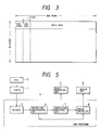
- Fig. 5 is a block diagram showing a conventional data reproducing device for playing a disc in which music data and image data including sub-codes have been recorded.
- the data reproducing device as shown in Fig. 5, comprises: a player 1; a sound generating unit 2 including an amplifier and a loudspeaker; a display unit 3; and a data processing unit 4.
- the player 1 reads music data, sub-codes, etc. from the disc D to apply a reproduction signal to the data processing unit 4.
- the unit 4 extracts the music data and image data from the output reproduction signal of the player 1, to control the sound generating unit 2 and the display unit 3.
- the output reproduction signal of the player 5 is first applied to a decoder 5 in the data processing unit 4, where it is subjected to deinterleaving and error correction, and the music data is applied through a processing circuit (not shown) to the sound generating unit 2 while the image data is applied to an instruction discriminating circuit 6.
- the instruction discriminating circuit 6 determines whether or not an image processing instruction is recorded in the second word (Fig. 4(B)) of the sub-code and outputs a detection signal when an image processing instruction is present.
- An instruction analyzing circuit 7 operates to analyze an image processing instruction, to thereby provide data which specify the colors of the picture elements of the picture according to the image data recorded in the sub-code.
- a display control circuit 8 forms video signals including color signals and synchronizing signals, so that the image data is displayed on the display unit 3.
- the music data recorded in the disc D is manually searched with the player 1 by fast forwarding or fast reversing, the player 1 performs a sequential operation where data at discontinuous parts of the disc D are reproduced sequentially.
- the music data even when sound reproduction is made with data obtained from separate parts of the disc, we hear it naturally.
- the image data recorded in the sub-code is a sequential data train. Therefore, if a discontinuous reproduction is produced, for instance, by manual search, the continuity of the image data is lost. As a result, the displayed picture has missing parts over the entire screen, suffers from double writing, or is abnormal in coloration. That is, the reproduction is unsatisfactory.
- the conventional data reproducing device is unreliable, and the user may find the resultant picture disagreeable.
- An object of this invention is to provide a data reproducing device in which the reproduced picture is free from the defects which otherwise may occur with the discontinuous reproduction of image data, whereby the user can observe the resultant picture at ease.
- JP-A-61080684 discloses a disc playing apparatus with a picture hold function.
- US-A-4694441 discloses a position control device for an optical disc system.
- a data reproducing device comprising: reading means for reading digitally recorded music data from a data carrier; and data processing means for producing a music signal and an image signal according to the music and image data, applying the music and image signals to sound generating means and display means, respectively, monitoring time data recorded in the data carrier, and capable of suspending reproduction of the image signal on the display means, characterised in that: the image signal reproduction is suspended upon the detection of a discontinuity in the time data.
- the music data and image data recorded in the carrier are read out by the reading means and then are applied to the data processing means.
- the data processing means produces the music signal and the image signal according to the music data and image data thus read out.
- the music signal and the image signal are applied to the sound generating means 2 and the display means, respectively.
- the data processing means monitors the time data which represents the lapse of time in the performance of a piece of music recorded in the data carrier. Upon detection of a discontinuous change of the time data, the data processing means determines therefrom that a manual search (discontinuous reproduction), such as a quick forwarding operation or quick reversing operation, has been carried out, and causes the display means to suspend the image reproduction, thereby eliminating the irregularities which otherwise may occur with the reproduced image in the discontinuous reproduction.
- a manual search discontinuous reproduction
- Fig. 2 is a block diagram showing one example of a data reproducing device according to this invention.
- those components which have been previously described with reference to Fig. 5 are therefore designated by the same reference numerals or characters.
- a disc player 2 reads music data and sub-codes from a disc D and applies them to a data processing circuit 4.
- the data processing circuit 4 extracts image data from the sub-code thus read, so that an image is displayed on a display unit 3.
- the data processing circuit 4 comprises a series circuit which includes a decoder 5 to which the output reproduction signal of the player 1 is applied, an instruction discriminating circuit 6, an instruction analyzing circuit 7, and a display control circuit 8.
- the output of the circuit 8 is supplied to the display unit 3.
- the data processing circuit 4 further comprises a series circuit of a Q signal extracting circuit 9 to which the output signal of the decoder 5 is applied, a Q signal discriminating circuit 10, and an interrupt processing circuit 11.
- the interrupt processing circuit 11 is designed to issue an interrupt instruction to the display control circuit 8.
- the music data and sub-code data read by the player 1 are applied to the decoder 5, where they are subjected to deinterleaving and error correction.
- the music data is applied through a processing circuit (not shown) to a sound generating unit 2 such as a loudspeaker system.
- the image data is supplied to the instruction discriminating circuit 6 to determine whether or not the image processing instruction is recorded in the second word of each unitary image data. If an image processing instruction is recorded, the circuit 6 applies a detection signal to the instruction analyzing circuit 7. In response to the detection signal, the instruction analyzing circuit 7 forms image data.
- the display control circuit 8 forms a video signal according to the image data thus formed, so that a picture is displayed on the display unit 3.
- the decoder 5 operates to extract the Q signal from the sub-code and outputs the same.
- the Q signal is one bit of the sub-code which consists of eight (8) bits per image word, and the unitary data consists of ninety-eight (98) frames (corresponding to one frame of the sub-code).
- the Q signal covers a 2-bit synchronizing signal, 4-bit control code, 4-bit address code, 72-bit data, and 16-bit error detecting code; i.e., ninety-eight (98) bits in total.
- the 72-bit data includes time data such as the above-described total time data and music time lapse data.
- the Q signal extracting circuit 9 decodes the time data from the Q signal and applies it to the Q signal discriminating circuit 10.
- the Q signal discriminating circuit 10 determines whether or not the time data increases or decreases regularly. During ordinary reproduction, the time data will increase with a predetermined regularity for every frame of the sub-code, however, the regularity is affected by fast-forwarding and fast-rewinding operations.
- the Q signal discriminating circuit 10 detects this condition to apply the detection signal to the interrupt processing circuit 11, whereupon the interrupt processing circuit 11 suspends the image display carried out under the control of the display control circuit 8, and erases the displayed picture.
- the Q signal discriminating circuit 10 cannot reproduce the time data because of scratches or the like on the disc D. Therefore, the resulting discontinuity in the time data is detected utilizing a certain width, to perform the picture erase control.
- the discontinuity in the time data indicating the music performance time is detected to thereby detect the discontinuous reproduction whereby the displayed picture is erased. Therefore, with the data reproducing device of the invention, the picture can be erased before it is affected by the manual search. Thus, the data reproducing device of the invention is reliable at all times.
Description
- This invention relates to a data reproducing device for reproducing music data and image data which are recorded on a data carrier.
- As shown in the signal format illustrated in Fig. 3, in addition to music data, a series of digital data called "sub-codes" are recorded on a compact disc in which music data are recorded in the form of digital data. Each sub-code is made up of eight (8) bits. Of the eight bits, two higher-order bits correspond to a P signal and a Q signal, and the remaining six bits are used as image data. The sub-code is so determined that ninety-eight image words correspond to one frame of the sub-code. The P signal indicates the top of a piece of music, and it is raised to "1" at the top of the piece of music and held at "0" at the other. positions. The Q signals are used to record a music number, data concerning the length of time for a piece of music (hereinafter referred to as "music time lapse data", when applicable), and data concerning the total time from the start (hereinafter referred to as "total time data", when applicable).
- For the image data, ninety-eight words each consisting of six bits are provided as shown in Fig. 4(A). Of the ninety-eight words, the first and second words are used as a synchronizing signal, and the remaining words are used as image data. The ninety-six words of image data are made up of four groups of unitary image data in which twenty-four words is a minimum unit.
- In the unitary image data, as shown in Fig. 4(B), the record mode is recorded in the first word, an image processing instruction is recorded in the second word, and error correction signs for the first and second words are recorded in the third and fourth words.
- As for the record mode, a line graphics mode and a TV graphics mode are provided. As for the image processing instruction, an instruction for covering a screen with a color, an instruction for applying two different colors to a screen forming units (fonts) to draw a figure, an instruction for moving an entire screen vertically or horizontally, and so forth are available.
- A channel number and color data for specifying picture color are recorded in the fifth and sixth words. Position data for indicating a data display position in the picture are recorded in the seventh and eight words, and data and error correction signs are recorded in the last sixteen words (i.e., the ninth through twenty-fourth words).
- Fig. 5 is a block diagram showing a conventional data reproducing device for playing a disc in which music data and image data including sub-codes have been recorded.
- The data reproducing device, as shown in Fig. 5, comprises: a
player 1; asound generating unit 2 including an amplifier and a loudspeaker; adisplay unit 3; and adata processing unit 4. Theplayer 1 reads music data, sub-codes, etc. from the disc D to apply a reproduction signal to thedata processing unit 4. Theunit 4 extracts the music data and image data from the output reproduction signal of theplayer 1, to control thesound generating unit 2 and thedisplay unit 3. - The output reproduction signal of the
player 5 is first applied to adecoder 5 in thedata processing unit 4, where it is subjected to deinterleaving and error correction, and the music data is applied through a processing circuit (not shown) to thesound generating unit 2 while the image data is applied to an instructiondiscriminating circuit 6. The instructiondiscriminating circuit 6 determines whether or not an image processing instruction is recorded in the second word (Fig. 4(B)) of the sub-code and outputs a detection signal when an image processing instruction is present. An instruction analyzingcircuit 7 operates to analyze an image processing instruction, to thereby provide data which specify the colors of the picture elements of the picture according to the image data recorded in the sub-code. In response to the output data of the instruction analyzingcircuit 7 and the output detection signal of the instructiondiscriminating circuit 6, adisplay control circuit 8 forms video signals including color signals and synchronizing signals, so that the image data is displayed on thedisplay unit 3. - In the case where, with the conventional data reproducing device, the music data recorded in the disc D is manually searched with the
player 1 by fast forwarding or fast reversing, theplayer 1 performs a sequential operation where data at discontinuous parts of the disc D are reproduced sequentially. As for the music data, even when sound reproduction is made with data obtained from separate parts of the disc, we hear it naturally. On the other hand, the image data recorded in the sub-code is a sequential data train. Therefore, if a discontinuous reproduction is produced, for instance, by manual search, the continuity of the image data is lost. As a result, the displayed picture has missing parts over the entire screen, suffers from double writing, or is abnormal in coloration. That is, the reproduction is unsatisfactory. Thus, the conventional data reproducing device is unreliable, and the user may find the resultant picture disagreeable. - An object of this invention is to provide a data reproducing device in which the reproduced picture is free from the defects which otherwise may occur with the discontinuous reproduction of image data, whereby the user can observe the resultant picture at ease.
- JP-A-61080684 discloses a disc playing apparatus with a picture hold function. US-A-4694441 discloses a position control device for an optical disc system.
- According to the present invention there is provided a data reproducing device comprising:
reading means for reading digitally recorded music data from a data carrier; and
data processing means for producing a music signal and an image signal according to the music and image data, applying the music and image signals to sound generating means and display means, respectively, monitoring time data recorded in the data carrier, and capable of suspending reproduction of the image signal on the display means, characterised in that:
the image signal reproduction is suspended upon the detection of a discontinuity in the time data. - The music data and image data recorded in the carrier are read out by the reading means and then are applied to the data processing means. The data processing means produces the music signal and the image signal according to the music data and image data thus read out. The music signal and the image signal are applied to the sound generating means 2 and the display means, respectively.
- The data processing means monitors the time data which represents the lapse of time in the performance of a piece of music recorded in the data carrier. Upon detection of a discontinuous change of the time data, the data processing means determines therefrom that a manual search (discontinuous reproduction), such as a quick forwarding operation or quick reversing operation, has been carried out, and causes the display means to suspend the image reproduction, thereby eliminating the irregularities which otherwise may occur with the reproduced image in the discontinuous reproduction.
- In the drawings:-
- Fig. 1 is a block diagram for a description of the principle of a data reproducing device according to this invention.
- Fig. 2 is a block diagram showing one example of the data reproducing device according to the invention.
- Fig. 3 is an explanatory diagram showing a format for signals recorded in a compact disc.
- Fig. 4 is an explanatory diagram showing a sub-code format.
- Fig. 5 is a block diagram showing a conventional data reproducing device.
- Fig. 2 is a block diagram showing one example of a data reproducing device according to this invention. In Fig. 2, those components which have been previously described with reference to Fig. 5 are therefore designated by the same reference numerals or characters.
- In the device of Fig. 2, a
disc player 2 reads music data and sub-codes from a disc D and applies them to adata processing circuit 4. Thedata processing circuit 4 extracts image data from the sub-code thus read, so that an image is displayed on adisplay unit 3. - The
data processing circuit 4 comprises a series circuit which includes adecoder 5 to which the output reproduction signal of theplayer 1 is applied, an instructiondiscriminating circuit 6, an instruction analyzingcircuit 7, and adisplay control circuit 8. The output of thecircuit 8 is supplied to thedisplay unit 3. Thedata processing circuit 4 further comprises a series circuit of a Qsignal extracting circuit 9 to which the output signal of thedecoder 5 is applied, a Q signaldiscriminating circuit 10, and aninterrupt processing circuit 11. Theinterrupt processing circuit 11 is designed to issue an interrupt instruction to thedisplay control circuit 8. - In the data reproducing device thus organized, the music data and sub-code data read by the
player 1 are applied to thedecoder 5, where they are subjected to deinterleaving and error correction. As a result, the music data is applied through a processing circuit (not shown) to asound generating unit 2 such as a loudspeaker system. From the sub-code data, the image data is supplied to the instructiondiscriminating circuit 6 to determine whether or not the image processing instruction is recorded in the second word of each unitary image data. If an image processing instruction is recorded, thecircuit 6 applies a detection signal to the instruction analyzingcircuit 7. In response to the detection signal, the instruction analyzingcircuit 7 forms image data. Thedisplay control circuit 8 forms a video signal according to the image data thus formed, so that a picture is displayed on thedisplay unit 3. - The
decoder 5 operates to extract the Q signal from the sub-code and outputs the same. The Q signal, as was described before, is one bit of the sub-code which consists of eight (8) bits per image word, and the unitary data consists of ninety-eight (98) frames (corresponding to one frame of the sub-code). The Q signal covers a 2-bit synchronizing signal, 4-bit control code, 4-bit address code, 72-bit data, and 16-bit error detecting code; i.e., ninety-eight (98) bits in total. The 72-bit data includes time data such as the above-described total time data and music time lapse data. - The Q
signal extracting circuit 9 decodes the time data from the Q signal and applies it to the Qsignal discriminating circuit 10. The Qsignal discriminating circuit 10 determines whether or not the time data increases or decreases regularly. During ordinary reproduction, the time data will increase with a predetermined regularity for every frame of the sub-code, however, the regularity is affected by fast-forwarding and fast-rewinding operations. The Qsignal discriminating circuit 10 detects this condition to apply the detection signal to the interruptprocessing circuit 11, whereupon the interruptprocessing circuit 11 suspends the image display carried out under the control of thedisplay control circuit 8, and erases the displayed picture. Sometimes the Qsignal discriminating circuit 10 cannot reproduce the time data because of scratches or the like on the disc D. Therefore, the resulting discontinuity in the time data is detected utilizing a certain width, to perform the picture erase control. - When during the reproduction of the music data and image data from the carrier, discontinuous reproduction is performed, for instance, by the manual search, according to the invention the discontinuity in the time data indicating the music performance time is detected to thereby detect the discontinuous reproduction whereby the displayed picture is erased. Therefore, with the data reproducing device of the invention, the picture can be erased before it is affected by the manual search. Thus, the data reproducing device of the invention is reliable at all times.
Claims (5)
- A data reproducing device comprising:
reading means (1) for reading digitally recorded music data from a data carrier (D); and
data processing means (4) for producing a music signal and an image signal according to the music and image data, applying the music and image signals to sound generating means (2) and display means (3), respectively, monitoring time data recorded in the data carrier, and capable of suspending reproduction of the image signal on the display means (3), characterised in that:
the image signal reproduction is suspended upon the detection of a discontinuity in the time data. - A device according to Claim 1, which includes means for reading a data carrier having a sub-code disposed therein, the sub-code data including a P signal indicating the beginning of a piece of music and a Q signal indicating music time data.
- A data reproducing device according to Claim 2, wherein the data processing circuit comprises:
decoder means (5) receiving the music data and the sub-code data from the reading means (1), and subjecting the music and sub-code data to de-interleaving and error correction;
instruction discriminating means (E) receiving the sub-code data from the decoder means (5), for determining if the sub-code data includes an image processing instruction, and outputting a detection signal when an image processing instruction is included in the sub-code data;
instruction analyzing means (7) receiving the detection signal and producing the image data in response thereto;
display control means (8) receiving the image data from the instruction analysing means and, in response producing a video signal which is applied to the display means (3);
Q signal extracting means (9) receiving the sub-code data from the decoder means (5) and decoding the time data from the Q signal;
Q signal discriminating means (10) receiving said time data from the Q signal extracting means and determining whether changes in the time data occur on a regular basis; and
interupt processing means (11) for suspending operation of the display control means to prevent image display on said display means (8) when the time data changes irregularly. - A data reproducing device according to Claim 3, wherein a regular change in the time data is one of a regular increase and a regular decrease.
- A data reproducing device according to any of claims 1 to 4, wherein the data carrier (D) is a compact disc.
Applications Claiming Priority (2)
| Application Number | Priority Date | Filing Date | Title |
|---|---|---|---|
| JP60503/88 | 1988-03-16 | ||
| JP63060503A JPH01236467A (en) | 1988-03-16 | 1988-03-16 | Information reproducing device |
Publications (3)
| Publication Number | Publication Date |
|---|---|
| EP0332776A2 EP0332776A2 (en) | 1989-09-20 |
| EP0332776A3 EP0332776A3 (en) | 1990-08-01 |
| EP0332776B1 true EP0332776B1 (en) | 1994-01-19 |
Family
ID=13144177
Family Applications (1)
| Application Number | Title | Priority Date | Filing Date |
|---|---|---|---|
| EP88308291A Expired - Lifetime EP0332776B1 (en) | 1988-03-16 | 1988-09-08 | Data reproducing device |
Country Status (4)
| Country | Link |
|---|---|
| US (1) | US4953153A (en) |
| EP (1) | EP0332776B1 (en) |
| JP (1) | JPH01236467A (en) |
| DE (1) | DE3887318T2 (en) |
Families Citing this family (12)
| Publication number | Priority date | Publication date | Assignee | Title |
|---|---|---|---|---|
| DE69028940T2 (en) * | 1989-03-28 | 1997-02-20 | Matsushita Electric Ind Co Ltd | Device and method for data preparation |
| US5132955A (en) * | 1990-01-02 | 1992-07-21 | Sonics Associates, Incorporated | Method and apparatus for synchronizing multiple cd players |
| JPH03283057A (en) * | 1990-03-30 | 1991-12-13 | Hitachi Ltd | Information recording and reproducing system and information recording and reproducing method using the system |
| EP0464482B1 (en) * | 1990-06-21 | 1996-08-28 | Yamaha Corporation | Display device for a compact disc player and a compact disc |
| JPH04206035A (en) * | 1990-11-30 | 1992-07-28 | Kogaku Denshi Kk | Cd-rom and reproducing system of cd-rom |
| DE69334107T2 (en) * | 1992-09-09 | 2007-10-18 | Canon K.K. | Information signal processing system with recording of management information in volatile memory means |
| US5734786A (en) * | 1993-10-20 | 1998-03-31 | E Guide, Inc. | Apparatus and methods for deriving a television guide from audio signals |
| US5499103A (en) * | 1993-10-20 | 1996-03-12 | E Guide, Inc. | Apparatus for an electronic guide with video clips |
| TW293981B (en) | 1995-07-21 | 1996-12-21 | Philips Electronics Nv | |
| JP3867447B2 (en) * | 1999-06-22 | 2007-01-10 | ソニー株式会社 | Disc type data recording / reproducing apparatus and information processing system equipped with disc type data recording / reproducing apparatus |
| US7181300B2 (en) | 2001-07-18 | 2007-02-20 | Gerald V Robbins | Single use media device |
| JP4211698B2 (en) * | 2004-07-09 | 2009-01-21 | ソニー株式会社 | Content data playback device |
Family Cites Families (12)
| Publication number | Priority date | Publication date | Assignee | Title |
|---|---|---|---|---|
| US4340916A (en) * | 1980-04-11 | 1982-07-20 | Sony Corporation | Apparatus and method for detecting discontinuities in time code addresses |
| JPS5748881A (en) * | 1980-09-08 | 1982-03-20 | Pioneer Electronic Corp | Video format signal recording and playback system |
| JPS5942679A (en) * | 1982-09-01 | 1984-03-09 | Matsushita Electric Ind Co Ltd | Magnetic recording and reproducing device |
| JPS5977777A (en) * | 1982-10-26 | 1984-05-04 | Mitsubishi Electric Corp | Video signal recording and reproducing device |
| JPS59117381A (en) * | 1982-12-23 | 1984-07-06 | Toshiba Corp | Magnetic recording and reproducing device |
| JPS59198508A (en) * | 1983-04-27 | 1984-11-10 | Pioneer Electronic Corp | Recording and reproducing system of video format signal |
| JPS6052960A (en) * | 1983-09-01 | 1985-03-26 | Sony Corp | Disk reproducer |
| US4694441A (en) * | 1983-10-14 | 1987-09-15 | Nippon Gakki Seizo Kabushiki Kaisha | Position control device for an optical reproduction system in an optical type disc reproduction device |
| JPS6180684A (en) * | 1984-09-28 | 1986-04-24 | Toshiba Corp | Reproducing device of digital disk record |
| JPS6180683A (en) * | 1984-09-28 | 1986-04-24 | Toshiba Corp | Reproducing device of digital disk record |
| JPH0687355B2 (en) * | 1986-05-06 | 1994-11-02 | パイオニア株式会社 | Display method on disk player |
| JPS6353778A (en) * | 1986-08-22 | 1988-03-08 | Sharp Corp | Magnetic recording and reproducing device |
-
1988
- 1988-03-16 JP JP63060503A patent/JPH01236467A/en active Pending
- 1988-09-08 DE DE3887318T patent/DE3887318T2/en not_active Expired - Fee Related
- 1988-09-08 EP EP88308291A patent/EP0332776B1/en not_active Expired - Lifetime
- 1988-09-09 US US07/242,444 patent/US4953153A/en not_active Expired - Fee Related
Also Published As
| Publication number | Publication date |
|---|---|
| JPH01236467A (en) | 1989-09-21 |
| EP0332776A2 (en) | 1989-09-20 |
| DE3887318T2 (en) | 1994-07-21 |
| DE3887318D1 (en) | 1994-03-03 |
| EP0332776A3 (en) | 1990-08-01 |
| US4953153A (en) | 1990-08-28 |
Similar Documents
| Publication | Publication Date | Title |
|---|---|---|
| KR910008467B1 (en) | Digital audio disk apparatus | |
| KR950030113A (en) | A method of constructing a data unit having a plurality of data block types, a data unit reproducing apparatus, and a data unit reproducing method | |
| EP0332776B1 (en) | Data reproducing device | |
| KR950012446A (en) | Playback device with time display | |
| KR960020477A (en) | Data playback device | |
| KR970703591A (en) | RECORDING MEDIUM, RECORDING METHOD AND APPARATUS, AND REPRODUCTION METHOD AND APPARATUS | |
| KR910008468B1 (en) | Apparatus for address information displaying | |
| US4860122A (en) | Device for reproducing a sequence of still pictures with an audio portion and without motion pictures between successive still pictures | |
| JP2785345B2 (en) | Video signal recording and playback device | |
| KR0123763B1 (en) | Introplaying method of compact disk | |
| JP2622828B2 (en) | Recording medium playback method | |
| JPH11238181A (en) | Image recorder | |
| KR980004876A (en) | Multi subtitle display device and method of DVD player | |
| KR970008234B1 (en) | Caption tent editing apparatus and method in double deck vcr | |
| KR930005729B1 (en) | Digital audio tape recorder available for displaying letter information | |
| KR950034234A (en) | Vis screen editing processing method and device | |
| JPS58133690A (en) | Disc reproducer | |
| KR0172325B1 (en) | Karaoke system | |
| JP3595424B2 (en) | Solid state memory device and solid state memory | |
| KR960002320A (en) | Vis screen processing method and device | |
| EP0811975A3 (en) | Editing method for recorded information | |
| JPS6258480A (en) | Information recording and reproducing system | |
| KR980004680A (en) | Synchronization Recording Method in Composite Device of Optical Disc Player and Video Cassette Recorder | |
| JPH04241244A (en) | Recording and reproducing device with time reservation recording function | |
| KR980011380A (en) | How to Display Tape Record Contents |
Legal Events
| Date | Code | Title | Description |
|---|---|---|---|
| PUAI | Public reference made under article 153(3) epc to a published international application that has entered the european phase |
Free format text: ORIGINAL CODE: 0009012 |
|
| AK | Designated contracting states |
Kind code of ref document: A2 Designated state(s): DE FR GB |
|
| 17P | Request for examination filed |
Effective date: 19900315 |
|
| PUAL | Search report despatched |
Free format text: ORIGINAL CODE: 0009013 |
|
| AK | Designated contracting states |
Kind code of ref document: A3 Designated state(s): DE FR GB |
|
| 17Q | First examination report despatched |
Effective date: 19921009 |
|
| GRAA | (expected) grant |
Free format text: ORIGINAL CODE: 0009210 |
|
| AK | Designated contracting states |
Kind code of ref document: B1 Designated state(s): DE FR GB |
|
| REF | Corresponds to: |
Ref document number: 3887318 Country of ref document: DE Date of ref document: 19940303 |
|
| ET | Fr: translation filed | ||
| PLBE | No opposition filed within time limit |
Free format text: ORIGINAL CODE: 0009261 |
|
| STAA | Information on the status of an ep patent application or granted ep patent |
Free format text: STATUS: NO OPPOSITION FILED WITHIN TIME LIMIT |
|
| 26N | No opposition filed | ||
| REG | Reference to a national code |
Ref country code: GB Ref legal event code: 746 Effective date: 19950809 |
|
| REG | Reference to a national code |
Ref country code: FR Ref legal event code: D6 |
|
| PGFP | Annual fee paid to national office [announced via postgrant information from national office to epo] |
Ref country code: GB Payment date: 19960830 Year of fee payment: 9 |
|
| PGFP | Annual fee paid to national office [announced via postgrant information from national office to epo] |
Ref country code: FR Payment date: 19960910 Year of fee payment: 9 |
|
| PGFP | Annual fee paid to national office [announced via postgrant information from national office to epo] |
Ref country code: DE Payment date: 19960913 Year of fee payment: 9 |
|
| PG25 | Lapsed in a contracting state [announced via postgrant information from national office to epo] |
Ref country code: GB Free format text: LAPSE BECAUSE OF NON-PAYMENT OF DUE FEES Effective date: 19970908 |
|
| PG25 | Lapsed in a contracting state [announced via postgrant information from national office to epo] |
Ref country code: FR Free format text: THE PATENT HAS BEEN ANNULLED BY A DECISION OF A NATIONAL AUTHORITY Effective date: 19970930 |
|
| GBPC | Gb: european patent ceased through non-payment of renewal fee |
Effective date: 19970908 |
|
| PG25 | Lapsed in a contracting state [announced via postgrant information from national office to epo] |
Ref country code: DE Free format text: LAPSE BECAUSE OF NON-PAYMENT OF DUE FEES Effective date: 19980603 |
|
| REG | Reference to a national code |
Ref country code: FR Ref legal event code: ST |