EP0332348B1 - Continuous casting machine dummy bar - Google Patents
Continuous casting machine dummy bar Download PDFInfo
- Publication number
- EP0332348B1 EP0332348B1 EP19890302109 EP89302109A EP0332348B1 EP 0332348 B1 EP0332348 B1 EP 0332348B1 EP 19890302109 EP19890302109 EP 19890302109 EP 89302109 A EP89302109 A EP 89302109A EP 0332348 B1 EP0332348 B1 EP 0332348B1
- Authority
- EP
- European Patent Office
- Prior art keywords
- sub
- bar
- bars
- recess
- spigot
- Prior art date
- Legal status (The legal status is an assumption and is not a legal conclusion. Google has not performed a legal analysis and makes no representation as to the accuracy of the status listed.)
- Expired
Links
- 238000009749 continuous casting Methods 0.000 title claims description 4
- 238000005266 casting Methods 0.000 description 2
- 230000006978 adaptation Effects 0.000 description 1
- 125000004122 cyclic group Chemical group 0.000 description 1
- 239000012530 fluid Substances 0.000 description 1
- 238000000034 method Methods 0.000 description 1
Images
Classifications
-
- B—PERFORMING OPERATIONS; TRANSPORTING
- B22—CASTING; POWDER METALLURGY
- B22D—CASTING OF METALS; CASTING OF OTHER SUBSTANCES BY THE SAME PROCESSES OR DEVICES
- B22D11/00—Continuous casting of metals, i.e. casting in indefinite lengths
- B22D11/08—Accessories for starting the casting procedure
- B22D11/081—Starter bars
Definitions
- the present invention relates to a bar for use as a dummy bar in a continous casting machine, according to the first part of claims 1.
- US Patent 4,043,383 discloses a dummy bar comprising a plurality of sub-bars each having a spigot on one end and a recess in the other end, so that sub-bars can be interconnected in series with the spigot of one sub-bar releasably engaging in the recess of the next sub-bar, in order to provide a dummy bar made up of a number of sub-bars.
- a dummy bar comprising a plurality of sub-bars each having a spigot on one end and a recess in the other end, so that the sub-bars can be interconnected in series, with the spigot of one sub-bar releasably engaging in the recess of the next sub-bar, in order to provide a dummy bar made up of a number of sub-bars and characterised by each sub-bar being provided with internally mounted hydraulic means adapted to be coupled with the next sub-bar and operable to urge the sub-bars together to ensure a stiff interconnection.
- the hydraulic means is in the form of a hydraulic piston and cylinder assembly mounted within one of the sub-bars, and interconnectable with the other sub-bar in use.
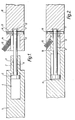
- a dummy bar is made up of series of sub-bars the ends of only two of which are shown.
- the end of one sub-bar 1 has a spigot 2 with a notch 3.
- a chamber 4 in which slides a piston 5 connected to a rod 6 which projects through the spigot 2 and at the end of the rod 6 is an eye 7.
- a recess 11 In the end of the other sub-bar 10 is a recess 11 with a secondary recess 12 at the back of the recess 11.
- Transversely through the sub-bar 10 extends a hole 13 which meets the sub-recess 12.
- the hole 13 through the sub-recess 12 receives a pin 16, in use.
- each sub-bar has at one end a spigot and associated piston cylinder assembly, and recesses with associated holes at its other end.
- the two sub-bars can be separated by a reverse procedure involving removing the pin 16 and applying hydraulic pressure into the left hand side of the chamber 4 to move the piston and piston rod to the right as shown in ( Figure 2), thereby separating the two sub-bars form one another.
Landscapes
- Engineering & Computer Science (AREA)
- Mechanical Engineering (AREA)
- Actuator (AREA)
Description
- The present invention relates to a bar for use as a dummy bar in a continous casting machine, according to the first part of claims 1.
- It is well known to use rigid dummy bars in the initial phase of a casting operation in a vertical, horizontal, or curved mould continuous casting machine. Such rigid bars are difficult to handle because they are usually very long, typically 10 to 20 m. Where different sizes are to be cast it is necessary to have a dedicated dummy bar for each size, or to use interchangeable taper adaptations at the mould end.
- US Patent 4,043,383 discloses a dummy bar comprising a plurality of sub-bars each having a spigot on one end and a recess in the other end, so that sub-bars can be interconnected in series with the spigot of one sub-bar releasably engaging in the recess of the next sub-bar, in order to provide a dummy bar made up of a number of sub-bars.
- In order to prevent working of the joints between the sub-bars when subject to the large reversing cyclic load in a continuous casting machine it is necessary for the joints between the sub-bars to be very stiff. Also for practical purposes, the joints need to be capable of being easily assembled and disassembled.
- According to the present invention there is provided a dummy bar comprising a plurality of sub-bars each having a spigot on one end and a recess in the other end, so that the sub-bars can be interconnected in series, with the spigot of one sub-bar releasably engaging in the recess of the next sub-bar, in order to provide a dummy bar made up of a number of sub-bars and characterised by each sub-bar being provided with internally mounted hydraulic means adapted to be coupled with the next sub-bar and operable to urge the sub-bars together to ensure a stiff interconnection.
- Preferably the hydraulic means is in the form of a hydraulic piston and cylinder assembly mounted within one of the sub-bars, and interconnectable with the other sub-bar in use.
- A preferred embodiment of the invention will now be described, by way of example, with reference to the accompanying drawings, wherein:
- Figure 1 is a cross-sectional view through two adjacent sub-bars of a dummy bar prior to interconnection;
- Figure 2 is a similar view to Figure 1 but with the two sub-bars of the dummy bar interconnected.
- Referring first to Figure 1, a dummy bar is made up of series of sub-bars the ends of only two of which are shown. The end of one sub-bar 1 has a
spigot 2 with a notch 3. Within the sub-bar 1 is achamber 4 in which slides apiston 5 connected to a rod 6 which projects through thespigot 2 and at the end of the rod 6 is an eye 7. In the end of theother sub-bar 10 is a recess 11 with a secondary recess 12 at the back of the recess 11. Transversely through thesub-bar 10 extends a hole 13 which meets the sub-recess 12. Also there is an inclined threadedhole 14 joining the recess 11, which receives agrub screw 15. The hole 13 through the sub-recess 12 receives apin 16, in use. - It is to be appreciated each sub-bar has at one end a spigot and associated piston cylinder assembly, and recesses with associated holes at its other end.
- The interconnection of two sub-bars will now be described, first hydraulic pressure is applied to the
chamber 4 in the sub-bar 1 to move the piston and associated rod 6 to the right as shown in the Figures where the rod 6 projects from thespigot 2. The eye of the rod 6 is positioned in the sub-recess 12 in theother sub-bar 10 and thepin 16 inserted into the hole 13 to interlock the rod 6 andsub-bar 2. By applying hydraulic fluid to the opposite part of thechamber 4, i.e. the right hand side of thepiston 5, the two sub-bars will be drawn together so that thespigot 2 engages in the recess 11. It is appreciated that by means of the hydraulic piston cylinder arrangement the two sub-bars can be brought together firmly. While still being held tightly together by the hydraulic pressure thegrub screw 15 is tightened into the notch 3 in thespigot 2 to secure the twosub-bars 1 and 10 together, this is a situation illustrated in Figure 2. - The two sub-bars can be separated by a reverse procedure involving removing the
pin 16 and applying hydraulic pressure into the left hand side of thechamber 4 to move the piston and piston rod to the right as shown in (Figure 2), thereby separating the two sub-bars form one another.
Claims (4)
Applications Claiming Priority (2)
| Application Number | Priority Date | Filing Date | Title |
|---|---|---|---|
| GB888805376A GB8805376D0 (en) | 1988-03-07 | 1988-03-07 | Continuous casting machine dummy bar |
| GB8805376 | 1988-03-07 |
Publications (2)
| Publication Number | Publication Date |
|---|---|
| EP0332348A1 EP0332348A1 (en) | 1989-09-13 |
| EP0332348B1 true EP0332348B1 (en) | 1991-05-29 |
Family
ID=10632969
Family Applications (1)
| Application Number | Title | Priority Date | Filing Date |
|---|---|---|---|
| EP19890302109 Expired EP0332348B1 (en) | 1988-03-07 | 1989-03-02 | Continuous casting machine dummy bar |
Country Status (2)
| Country | Link |
|---|---|
| EP (1) | EP0332348B1 (en) |
| GB (1) | GB8805376D0 (en) |
Family Cites Families (4)
| Publication number | Priority date | Publication date | Assignee | Title |
|---|---|---|---|---|
| FR1070952A (en) * | 1952-02-20 | 1954-08-20 | Boehler & Co Ag Geb | Downpipe or the like for bar casting installation |
| FR1220316A (en) * | 1958-02-21 | 1960-05-24 | British Iron Steel Research | Method and apparatus for continuous metal casting |
| GB1119182A (en) * | 1965-04-01 | 1968-07-10 | Ashmore Benson Pease And Compa | Starting bars for continuous casting |
| US4043383A (en) * | 1976-09-23 | 1977-08-23 | Koppers Company, Inc. | Continuous casting starting bar and stowage thereof |
-
1988
- 1988-03-07 GB GB888805376A patent/GB8805376D0/en active Pending
-
1989
- 1989-03-02 EP EP19890302109 patent/EP0332348B1/en not_active Expired
Also Published As
| Publication number | Publication date |
|---|---|
| GB8805376D0 (en) | 1988-04-07 |
| EP0332348A1 (en) | 1989-09-13 |
Similar Documents
| Publication | Publication Date | Title |
|---|---|---|
| AU668481B2 (en) | Tooth to adapter coupler | |
| US5695081A (en) | Uniform shelving system | |
| EP0032790B1 (en) | Locking device for excavating equipment | |
| US4690411A (en) | Bonded mechanically inner connected seal arrangement for a blowout preventer | |
| CA1061983A (en) | Junction device for tridimensionally extending trussed structures | |
| US4926537A (en) | Tie rod and ball joint separator | |
| EP0235581B1 (en) | Coupling, especially for a diamond drill bit with a tube shaft and tube winding connection | |
| US4936500A (en) | Bolt-type boiler wall tube tool | |
| US4870739A (en) | Apparatus for removing pins from connecting link boat hardware | |
| EP0469655B1 (en) | Floating construction assembled from several parts | |
| US5588771A (en) | Connector for coupling a pair of rods | |
| ES2043145T3 (en) | DETACHABLE HYDRAULIC COUPLING IN CASE OF OVERLOAD. | |
| EP0332348A1 (en) | Continuous casting machine dummy bar | |
| CA2383426A1 (en) | Hydraulic rod connector system | |
| US5379535A (en) | Replaceable excavating tooth assembly | |
| US4625820A (en) | Crawler frame to base frame connection | |
| US3901042A (en) | Reinforced concrete pile and a method of manufacturing such a pile | |
| WO1990008234A1 (en) | A device for detachably coupling an implement to a vehicle | |
| NO843246L (en) | CHAIN CONNECTOR | |
| DE19906126C2 (en) | Device and method for loosening connecting bolts | |
| WO1999042733A1 (en) | Method and device for jointing rods and piston pump including the device | |
| EP0033201B1 (en) | Heat exchanger frame components | |
| US2384161A (en) | Press structure | |
| US2296182A (en) | Clamp type carrier bar | |
| JPH08506530A (en) | Tool fixing member for mechanical hammer |
Legal Events
| Date | Code | Title | Description |
|---|---|---|---|
| PUAI | Public reference made under article 153(3) epc to a published international application that has entered the european phase |
Free format text: ORIGINAL CODE: 0009012 |
|
| AK | Designated contracting states |
Kind code of ref document: A1 Designated state(s): FR GB |
|
| 17P | Request for examination filed |
Effective date: 19891003 |
|
| 17Q | First examination report despatched |
Effective date: 19891123 |
|
| GRAA | (expected) grant |
Free format text: ORIGINAL CODE: 0009210 |
|
| AK | Designated contracting states |
Kind code of ref document: B1 Designated state(s): FR GB |
|
| ET | Fr: translation filed | ||
| PLBE | No opposition filed within time limit |
Free format text: ORIGINAL CODE: 0009261 |
|
| STAA | Information on the status of an ep patent application or granted ep patent |
Free format text: STATUS: NO OPPOSITION FILED WITHIN TIME LIMIT |
|
| 26N | No opposition filed | ||
| PGFP | Annual fee paid to national office [announced via postgrant information from national office to epo] |
Ref country code: FR Payment date: 19930226 Year of fee payment: 5 |
|
| PGFP | Annual fee paid to national office [announced via postgrant information from national office to epo] |
Ref country code: GB Payment date: 19930301 Year of fee payment: 5 |
|
| PG25 | Lapsed in a contracting state [announced via postgrant information from national office to epo] |
Ref country code: GB Effective date: 19940302 |
|
| GBPC | Gb: european patent ceased through non-payment of renewal fee |
Effective date: 19940302 |
|
| PG25 | Lapsed in a contracting state [announced via postgrant information from national office to epo] |
Ref country code: FR Effective date: 19941130 |
|
| REG | Reference to a national code |
Ref country code: FR Ref legal event code: ST |