EP0331896A2 - Inserting, storing and dispensing device for objects and sheetlike articles to be stored in cassettes - Google Patents
Inserting, storing and dispensing device for objects and sheetlike articles to be stored in cassettes Download PDFInfo
- Publication number
- EP0331896A2 EP0331896A2 EP89101531A EP89101531A EP0331896A2 EP 0331896 A2 EP0331896 A2 EP 0331896A2 EP 89101531 A EP89101531 A EP 89101531A EP 89101531 A EP89101531 A EP 89101531A EP 0331896 A2 EP0331896 A2 EP 0331896A2
- Authority
- EP
- European Patent Office
- Prior art keywords
- organ
- cassette
- cassettes
- conveyor
- opening
- Prior art date
- Legal status (The legal status is an assumption and is not a legal conclusion. Google has not performed a legal analysis and makes no representation as to the accuracy of the status listed.)
- Ceased
Links
Images

Classifications
-
- G—PHYSICS
- G07—CHECKING-DEVICES
- G07D—HANDLING OF COINS OR VALUABLE PAPERS, e.g. TESTING, SORTING BY DENOMINATIONS, COUNTING, DISPENSING, CHANGING OR DEPOSITING
- G07D11/00—Devices accepting coins; Devices accepting, dispensing, sorting or counting valuable papers
- G07D11/009—Depositing devices
- G07D11/0096—Accepting paper currency or other valuables in containers, e.g. in code-marked envelopes
-
- G—PHYSICS
- G07—CHECKING-DEVICES
- G07D—HANDLING OF COINS OR VALUABLE PAPERS, e.g. TESTING, SORTING BY DENOMINATIONS, COUNTING, DISPENSING, CHANGING OR DEPOSITING
- G07D11/00—Devices accepting coins; Devices accepting, dispensing, sorting or counting valuable papers
- G07D11/10—Mechanical details
- G07D11/14—Inlet or outlet ports
Definitions
- the invention relates to a device for inputting, storing and dispensing objects to be stored in cassettes and sheet-like material according to the preamble of patent claim 1.
- a device for entering, storing and dispensing objects to be stored in cassettes and of sheet-like goods is indicated wherever sheet-like goods, as well as small non-sheet-shaped parts, or entire bundles of sheet-like goods are to be protected from violent access or environmental influences.
- a device of this type is described in EP-A 0182 137. It is a cash vault which is at cash desks of financial institutions, e.g. B. banks are used and designed so that larger amounts from an armored vault can only be delayed by funding.
- the well-known cash vault has z. B. the local currency and cassettes, in the z. B. bundles of banknotes of other currencies, coins, jewelry and the like can be stowed, two separate openings.
- the cash register can be placed between two cash counters. Each cashier can use his terminal to control only the storage units and storage spaces assigned to him.
- the invention has for its object to provide a device that allows objects to be stored in cassettes and sheet-like material Space-saving and quickly secured to stow away and cassettes and sheet-like goods to go out in one place.
- the cassette is held self-locking or in the immediate vicinity of a dead center both when it is received by a conveyor and in the delivery position in a mechanical dead center of the swivel mechanism of a swiveling member.
- This position of the dead centers results in a smooth and in no way jerky start-up of the pivotable member of the device.
- the cassette, which originates from different conveyors, and the sheet-like material can be made exactly one opening by means of the pivotable member. Thanks to this exact positioning, the opening can be made with minimal dimensions. This small opening is significantly more secure against external interference and can also be closed more effectively against the use of force than a large opening.
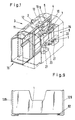
- the device for entering, storing and dispensing objects that can be stored in cassettes 1 and sheet-shaped goods 2 is designed as a cash vault 3, which is shown in FIG. 1 with a partial section through its vault interior 4 and its armor 5.
- cassettes 1 with e.g. Hard money, banknotes individually or in bundles of foreign currencies, special coins, jewelery or securities, and 10 banknotes 2 stored on several rolls of a roll storage device as sheet-shaped goods separated according to currency and values.
- the roll storage device 10 can be designed in accordance with the storage device described in the European patent application 88103427.6 which does not belong to the prior art.
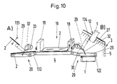
- the cash vault 3 is usually set up between two cash counters and is operated jointly by two cashiers A, B, as indicated in FIG. 10.
- Each cashier has on his side a terminal 11 for data input for a control device (not shown) in the safe door 16 for the cash safe 3, and an input and output opening 12 for the objects stored in the cassettes 1 and the bank notes 2.
- the input of the bank notes 2 takes place for both cashiers jointly through an input opening 13 in the middle of the surface of the cash safe 3.
- the banknotes 2 inserted into the opening 13 are separated by a separating mechanism, not shown, by means of a testing device (not shown) (in particular for sticking together, possibly also for authenticity) checked, and stored on a conveyor 15 in the roll memory 10.
- the cassettes 1 are in the cassette memory 9.
- the input, storage and output are controlled by the control device, the terminal 11 of which can be seen in FIG. 1 on the top of the cash safe 3, and also the composition of the bank notes 2 Nem banknote bundle 2, starting from the roll store 10.
- the banknote or banknotes 2 are fetched from the roll store 10 by the conveyor 15 and stored in a collecting box 19. From this collecting box 19, the bundle 2, as shown schematically in FIG. 10, depending on which cashier A or B it is intended for, is pushed with a conveyor designed as a slide 18 to a right or left device 20 in the safe interior 4.
- the device 20 takes over the bundle of banknotes 2 and pushes it through the right or left opening 12 for removal by the cashier in question.
- the cassette storage 9 has two internal storage spaces 21 for the cassettes 1, a horizontal transverse displacement device 22 and a lift 23 for vertical transport.
- a cassette 1 selected by the control device is pushed over the transverse shifting device 22 from its place in one of the two storage spaces 21 to the lift 23, lifted by this to the device 20 and, as described below, taken over by the latter and then transported through the opening 12, where its content is removed by the cashier B.
- the cassette 1 is either z. B. filled with banknotes 2, or bundles, hard money, etc., or withdrawn empty through the opening 12 and returned to their original place in one of the storage spaces 21.
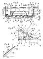
- the device 20 used for dispensing bundles of banknotes 2 and for receiving and moving the cassette 1; is shown in a plan view in Fig. 2 and in a side layer in Fig. 3 and 4 respectively.
- the device 20 is fastened with a right and left flange 25 and 26 to a support 8 (FIG. 1) which can be pulled out of the safe interior 4.
- the bundle of banknotes 2 and the cassette 1 can be guided through the opening 12, which is kept small for security reasons, and lie there within easy reach for the cashier, the bundle of banknotes 2 and the cassettes 1 are inserted via a pivotable plate-shaped member 29 direction 20 brought directly under the opening 12, and then pushed through it.
- the opening 12 is only open during dispensing. The rest of the time it is closed with a slide 27.
- the pivoting of the organ 29 takes place about a pivot axis 30 by means of two cranks 31 and two angle levers 32, the two cranks 31 being fastened in a rotationally fixed manner to a drive shaft 33.
- the axis 33 is rotated by a motor 35 attached to the flange 26. As shown in Fig.
- the drive shaft 33 is above and parallel to the pivot axis 30, and is supported by a bearing 37 and 39 in the flanges 25 and 26 of the device 20.
- the axis 33 and the motor 35 are connected to one another via a coupling 40.
- Each of the other two angle levers 32 is pivotally mounted at the end of the crank 31 and approximately in the middle of an upwardly bent outer side edge 41 or 42 of the member 29 by bolts 43 and 44 pressed into it.
- the bolts 43 and 44 are secured by snap rings from slipping out of a bore 47 in the crank 31 or the edges 41 and 42.
- the pivot axis 30 is horizontal, and is also rotatably held on each of the flanges 25 and 26 by a bearing 45 and 46, respectively.
- the organ 29 is pivotally supported on the axis 30 by a bearing 49 and 50 in the rearward extension of its edges 41 and 42.
- the pivot axis 30 is thus freely rotatable in the flanges 25 and 26, and also the member 29 freely rotatable on the pivot axis 30.
- the bearings 45 and 49, and 46 and 50 are each spaced apart by a spacer bushing 51 and 52. The spacers 51 and 52 distance and position the member 29 laterally to the two flanges 25 and 26.
- the cranks 31 have the bore 47 at one end and a bore 48 at the other.
- the bore 47 receives the bolt 43 and the drive shaft 33 is inserted in the bore 48.
- an outlet is located in the surface a notch towards the bore 48, but radially limited to the outside.
- a pin 54 inserted through the drive shaft 33, as indicated in FIGS. 3 and 4.
- the pin 54 serves to transmit power from the drive shaft 33 to the crank 31.
- the movement of the pin 54 out of the notch of the crank 31 is achieved by a snap ring seated in a groove in the drive shaft 33 55 prevents that pushes against the crank 31; the radial closure of the notch prevents the pin 54 from slipping out radially.
- Each angle lever 32 has an upwardly directed knee 56 approximately in its center, the knee legs forming an angle of approximately one hundred and thirty degrees in the hollow of the knee.
- One knee leg is, as described above, rotatable on the crank 31 with a bolt 43, and the other is rotatable about a further bolt 44 and secured with a snap ring, approximately in the middle of the edge 41 or 42 of the organ 29.
- a leg 57 extends from the end of the angle lever 32, which is mounted in the organ 29 with the bolt 44, at approximately a right angle in the direction of the knee 56.
- toothed belt wheels 60, 61, 62 and 63 which are non-rotatably pinned to the pivot axis 30.
- the pinning takes place analogously to the crank 31 on the drive shaft 33.
- the toothed belt wheels 60 to 63 are driven by a motor 65 via the pivot axis 30.
- an axis 70 and 71 On the two edges of the side of the organ 29 opposite the pivot axis 30, there are, each held by two bearing blocks, an axis 70 and 71, each with two toothed belt wheels 72 and 73.
- the toothed belt wheels 60, 61 and 62, 63 and the toothed belt wheels 72 and 73 are connected by two pairs of toothed belts 66 and 67, respectively.
- the four toothed belts 66 run over the top 75 of the organ 29 and back again via the bottom 76.
- a slide 77 is clamped at its outer edges to one of the pairs of toothed belts 66 and 67 in such a way that it can be displaced parallel to the swivel axis 30 via the underside 76.
- About an eighty percent of the width of the slide 77 extends on the side facing the pivot axis 30 symmetrically to the center of the side, an angled extension 79, which serves to push the cassette 1 through the opening 12.
- An angled gripper 81 is located at the same height as the extension 79 on the outer edges of the slide 77. In each of the Gripper 81 grips an eyelet 82 on the lower outer edge of the cassette 1, as shown in FIG. 9, for retracting the cassette 1.
- An internally hollow shaft 84 is pushed over the pivot axis 30. On each side of the shaft 84 there is a spacer 85 or 87 on the swivel axis 30. In its position, the shaft 84 is fixed by a snap ring 90 in a groove in the swivel axis 30 on the side facing the toothed belt wheel 62 and on the opposite side the spacer 85 abuts the toothed belt wheel 61 directly.
- the shaft 84 has a toothed belt wheel 91 and a toothed wheel 92 on the side adjoining the spacer disk 85 and then a spacer beech 93 and a toothed belt wheel 94 alternately in three times.
- the three toothed belt wheels 94 are approximately symmetrical to the center of the organ 29.
- Three toothed belts 101 run over them on the top and bottom sides 75 and 76.
- the toothed belts 101 are supported by three toothed belt wheels 102 on a shaft 99 redirected.
- a hold-down device 103 is located above the top 75.
- the hold-down device 103 has a bracket 104, a shaft 105 parallel to the swivel axis 30 with a toothed belt wheel 100 pinned analogously to crank 31, and three elastic transport rollers 109 which, in the swiveling process described below, act directly on the toothed belt 101 come to lie, and a spring plate 110.
- the spring plate 110 is welded to the side of the bracket 104 pointing away from the pivot axis 30.
- the bracket 104 is screwed to two rails 111 approximately in the middle.
- the rails 111 are each pivotably supported by means of a bearing 112 on an axis 113 which is rigidly connected to the edges 41 and 42 at the same height as the pivot axis 30 and parallel to it.
- the shaft 105 is held in a respective bearing 115.
- the toothed belt wheel 100 is located next to one of the rails 111 within the hold-down device 103.
- the bracket 104 forms an angle of approximately thirty degrees with each rail 111, the angle apex pointing to the shaft 105.
- a toothed belt wheel 97 and a toothed wheel 96 run on the axis 113, through one of the rails 111 on one end face and through one on the other side Clamping ring 117 are prevented from migrating sideways.
- the gear 92 on the shaft 84 drives the gear 96 and the toothed belt wheel 97 directly.
- a toothed belt 119 runs to the toothed belt wheel 100 via the toothed belt wheel 97.
- the transmission via the toothed wheels 92, 96, the toothed belt wheel 97, the toothed belt 119 and the toothed belt wheel 100 to the transport rollers 109 serves to transport the transport rollers 109 at the same peripheral speed as the toothed belt 101 to let go.
- a tension spring 120 is arranged at a distance of a few millimeters from the rail 111, which pulls the hold-down device 103 toward the member 29. Also attached to the upper edge of the bracket 104 is a plastic band 121 which, when the organ 29 is in a horizontal position, distances the hold-down device 103 from the organ 29 a few millimeters against the force of the two springs 120, as shown in FIG. 3.
- the two rail guides 122 are mirror images of one another. They are shaped in such a way that they each have an attachment 123 on their part lying on the underside 76 of the organ 29, the two attachments pointing towards one another parallel to the organ 29. Each of the rail guides 122 is pulled by a spring 125 to the relevant edge 41, 42. At the upper edge of the rail guide 122, an extension 129 points away from the organ 29. Also on the upper edge of the rail guide 122, a pin-shaped extension 130 is formed as an axis in the longitudinal direction thereof, which is inserted in a plastic bearing block 131, preferably made of Delrin.
- the plastic blocks 131 are screwed to the edges 41 and 42.
- the bolt 44 of the angle lever 32 in the edges 41 and 42 extends through an opening in each of the rail guides 122. A pivoting movement of each rail guide 122 is thus not hindered by the bolts 44.
- the cassettes 1 are an internally hollow rectangular parallelepiped that is open on one of its long sides. As shown in FIG. 9, one of the eyelets 82 is formed on the side opposite the open long side in the vicinity of the edge to the broad sides and in the immediate vicinity of one of the cover surfaces. A projection 127 runs along each of the eyelets 82 along the respective side surface. As shown in FIGS. 6 and 7, the cassette 1 is held by the projection 123 of the rail guide 122 at its projection 127, gripped or slides on it, as described further below.
- the pivotable member 29 To receive the bundle of banknotes 2 from the collecting box 19, the pivotable member 29 is in a horizontal position, as shown in FIGS. 5b and 10. In the horizontal position, the pivot point with the bolt 43 of the angle lever 32 and the crank 31 lies slightly above the connecting line between the center of the drive shaft 33 and the center of the bolt 44, ie the pivot mechanism with the crank 31 and the angle lever 32 has not yet reached its bottom dead center reached.
- the hold-down device 103 is lifted off the organ 29 by the plastic band 121, so that the bundle of banknotes 2 pushed by the slide 18 out of the collecting box 19 onto the top 75 of the organ 29 is not hindered.
- a toothed belt 132 is connected to the conveyor 18 via a slip clutch, not shown, and drives the axle 84 via the toothed belt wheel 91.
- the axis 84 drives the toothed belts 101 via the three toothed belt wheels 94, and the toothed wheel 96 with the toothed belt wheel 97 and the axis 113 via the toothed wheel 92.
- the conveying speed of the banknote bundle 2 coincides with the speed of the toothed belt 101 and the peripheral speed of the three elastic rollers 109. If about twenty percent of the banknote length has passed under the transport rollers 109, the movement is stopped.
- the member 29 is pivoted upward about the pivot axis 30 to the axis 33.
- the hold-down device 103 touches with its spring plate 110 the banknote bundle 2 lying on the organ 29.
- the transport rollers 109 also press onto the banknote bundle 2.
- the banknote bundle 2 is now firmly clamped in place and pivoting continues to an angle of forty degrees from the horizontal as shown in FIG. 5c until the bundle of banknotes 2 is directly under the opening 12.
- the drive via the toothed belt 132 is started again and the bundle of banknotes 2 is pushed through the opening 12 until it is just the Has passed transport rollers 109, but is still held properly by the spring plate 110 of the hold-down device 103.
- the banknote bundle 2 now protrudes from the opening 12 in a good gripping position for the cashier and can be removed.
- the organ 29 is held in this inclined position only by the force of the motor 35. This is possible because the weight of the bundle of banknotes 2 is low and no forces are exerted on the organ 29 through the opening 12.
- the removal of the banknote bundle 2 is determined by an electro-optical sensor 133 in the opening 12. After removal, the organ 29 is pivoted back into the horizontal position, as shown in Fig. 5b.
- the device 20 is ready to receive bundles of banknotes 2 again.
- the crank 31 is rotated downward by about seven degrees beyond the position shown in FIG. 5b into the position shown in FIG. 5a.
- the organ 29 is still in a horizontal position since the rotation takes place around the bottom dead center.
- the pivot point with the bolt 43 of the angle lever 32 and the crank 31 lies slightly, as shown in FIG. 5a, below the connecting line between the center of the drive shaft 33 and the center of the bolt 44, ie the pivot mechanism with crank 31 and angle lever 32 has just passed bottom dead center.
- the leg 57 has been moved with its free end by the additional rotation upward and pushes the shoulder 129 upward with its end.
- the rail guide 122 is pivoted about its axis, formed from the extensions 130 which are mounted in the blocks 131, ie the shoulder 123 is pressed outwards, as shown in FIG. 6.
- the slide 77 on the underside 76 of the organ 29 is in a position near the pivot axis 30.
- the cassette 1 selected by the control device is pushed by the transverse displacement device 22 to the lift 23, and is lifted by the latter under the organ 29.
- each of the cassettes 1 has two eyes 82 near its outer lower edge. These two eyes 82 snap into the grippers 81 of the slide 77.
- the motor 35 rotates both cranks 31 upwards, the leg 57 leaves the extension 130.
- Each of the rail guides 122 is, as in Fig. 6 ge shows, pulled by the spring 125 against the edge 41 or 42, whereby the cassette 1 is held with its lateral projection 127 by the extension 123 of the rail guide 122 on the member 29. Since this rotation takes place immediately around the bottom dead center of the pivot mechanism, the organ 29 has not carried out any pivot so far. A swivel now begins slowly and the motor 35 continues to rotate until the top dead center is exceeded when the organ 29 is inclined by approximately sixty degrees to the horizontal, and the hollow of the knee 56 of the angle lever 32 on the drive shaft 33, as shown in FIG. 5d, lies. In this position, the cassette 1 is located under the opening 12.
- the opening 12 is opened by the slide 27 and the cassette 1 sliding on the rail guide 122 through the grippers 81 and the attachment 79 on the slide 77 from the motor 65 via the shaft 30, the toothed belt wheels 60 to 63 and the toothed belt 119 shifted.
- Below the opening 12 there are further rails 134 in the opening 12, in which the projection 127 of the cassette 1 slides further as soon as it protrudes beyond the rail guides 122.
- the displacement of the slide 77 is stopped as soon as the cassette 1 comes close to the upper edge of the organ 29.
- the cassette 1 is now beyond the opening 12 and its content is removed by the cashier.
- the same cassette 1 is refilled or empty, it cannot be removed, is pulled back again, the slide 27 is closed, and the member 29 is pivoted back into the horizontal position shown in FIG. 5a, the rail guides 122 being opened again.
- the lift 23 takes over the cassette 1 in order to place it in the storage space 21 of the storage 5 via the transverse displacement device 22.
- the pivotable member 29 and the cassette storage 9 are designed so that cassettes 1 can be used with a single and double fill level.
- the slightly raised hold-down device 103 when inserting the banknote bundle 2 from the collecting box 19 onto the upper side 75 of the organ 29 has also proven itself; with appropriate dimensioning of the diameter of the transport rollers 109 and the force of the spring 120, however, the lifting could be dispensed with.
- belts with an adapted width can also be used with a slight structural adjustment.
Landscapes
- Physics & Mathematics (AREA)
- General Physics & Mathematics (AREA)
- Pile Receivers (AREA)
- Delivering By Means Of Belts And Rollers (AREA)
- Sheets, Magazines, And Separation Thereof (AREA)
Abstract
Die z. B. als Kassentresor (3) ausgebildete Vorrichtung hat zwei Öffnungen (12) zum Ausgeben von Banknoten (2) und in Kassetten (1) aufbewahrten Wertgegenständen aus dem Tresorinnenraum (4). Ein mit Fördermitteln ausgerüstetes schwenkbares Organ übernimmt die Kassetten (1) bzw. die Banknoten (2) von je einem im Tresorinnenraum (4) angeordneten Förderer und schiebt sie durch eine der Öffnungen (12). Nach dem Entleeren oder Beladen werden die Kassetten (1) vom Organ wieder zurückgezogen und an den Förderer (23) übergeben.The z. B. designed as a cash vault (3) has two openings (12) for dispensing banknotes (2) and valuables stored in cassettes (1) from the vault interior (4). A pivotable member equipped with conveying means takes over the cassettes (1) or the banknotes (2) from a respective conveyor arranged in the safe interior (4) and pushes them through one of the openings (12). After emptying or loading, the cassettes (1) are withdrawn by the organ and handed over to the conveyor (23).
Description
Die Erfindung betrifft eine Vorrichtung zum Eingeben, Aufbewahren und Ausgeben von in Kassetten aufzubewahrenden Objekten und von blattförmigem Gut gemäß dem Oberbegriff des Patentanspruchs 1.The invention relates to a device for inputting, storing and dispensing objects to be stored in cassettes and sheet-like material according to the preamble of
Eine Vorrichtung zum Eingeben, Aufbewahren und Ausgeben von in Kassetten aufzubewahrenden Objekten und von blattförmigem Gut, ist überall dort angezeigt, wo blattförmiges Gut, sowie kleine nicht blattförmige Teile, oder ganze Bündel blattförmigen Guts vor gewaltsamem Zugriff oder Umwelteinflüssen geschützt werden sollen. Eine Vorrichtung dieser Art ist in der EP-A 0182 137 beschrieben. Es handelt sich um einen Kassentresor der an Kassenschaltern von Geldinstituten, z. B. Banken eingesetzt und so ausgeführt ist, daß größere Beträge aus einem gepanzerten Tresorinnenraum durch Fördereinrichtungen nur verzögert entnommen werden können. Der bekannte Kassentresor hat zur Ein- und Ausgabe von Banknoten z. B. der Landeswährung und von Kassetten, in die z. B. Banknotenbündel anderer Währungen, Münzen, Schmuck und dgl. mehr verstaut werden können, zwei getrennte Öffnungen. Der Kassentresor kann zwischen zwei Kassenschaltern aufgestellt werden. Jeder Kassierer kann mit seinem Terminal nur ihm zugeordnete Speichereinheiten und Speicherplätze ansteuern.A device for entering, storing and dispensing objects to be stored in cassettes and of sheet-like goods is indicated wherever sheet-like goods, as well as small non-sheet-shaped parts, or entire bundles of sheet-like goods are to be protected from violent access or environmental influences. A device of this type is described in EP-A 0182 137. It is a cash vault which is at cash desks of financial institutions, e.g. B. banks are used and designed so that larger amounts from an armored vault can only be delayed by funding. The well-known cash vault has z. B. the local currency and cassettes, in the z. B. bundles of banknotes of other currencies, coins, jewelry and the like can be stowed, two separate openings. The cash register can be placed between two cash counters. Each cashier can use his terminal to control only the storage units and storage spaces assigned to him.
Befinden sich Kunden an beiden Schaltern ist es leicht möglich, daß die Ein- bzw. Ausgaben durch die beiden Kassierer verwechselt werden. Diese Verwechslungen werden einerseits bei der Eingabe durch den Kassentresor als Fehler signalisiert und bei der Ausgabe vom betreffenden Kassierer festgestellt, führen aber zu unerfreulichen Verzögerungen und Fehlermöglichkeiten. Wird bei der Eingabe der Banknotenbündel eine Fehleingabe z. B. durch zusammenklebende Noten durch der Kassentresor festgestellt, so ist bei der bestehenden Anlage keine unmittelbare Rückgabe möglich, der Kassentresor ist blockiert.If customers are at both counters, it is easily possible for the two cashiers to confuse the inputs and outputs. On the one hand, these mix-ups are signaled as errors by the cash register when they are entered and determined by the cashier concerned when they are output, but they lead to unpleasant delays and possibilities for errors. If an incorrect entry z. B. determined by sticky notes by the cash vault, so no immediate return is possible in the existing system, the cash vault is blocked.
Der Erfindung liegt die Aufgabe zugrunde, eine Vorrichtung zu schaffen, die es erlaubt, in Kassetten aufbewahrbare Objekte und blattförmiges Gut platzsparend und schnell gesichert zu verstauen und Kassetten und blattförmiges Gut an einem gemeinsamen Ort auszugehen.The invention has for its object to provide a device that allows objects to be stored in cassettes and sheet-like material Space-saving and quickly secured to stow away and cassettes and sheet-like goods to go out in one place.
Die erfindungsgemäße Lösung der Aufgabe ist Gegenstand des Patentanspruchs 1. Bevorzugte Ausführungsarten sind in den Ansprüchen 2 bis 15 umschrieben.The achievement of the object is the subject of
Die durch die Erfindung erzielten Vorteile sind im wesentlichen darin zu sehen, daß für je einen Bediener nur ihm zugeordnetes blattförmiges Gut und Kassetten an einer gemeinsamen Einrichtung entnehmbar sind, und in einer bevorzugten Ausführungsform sowohl die Kassetten, als auch das blattförmige Gut aus einer Öffnung so weit herausgeschoben werden, daß sie ergonomisch gut greifbar sind.The advantages achieved by the invention are essentially to be seen in the fact that for each operator only sheet material and cassettes assigned to him can be removed from a common device, and in a preferred embodiment, both the cassettes and the sheet material from an opening be pushed far out that they are ergonomically easy to grasp.
Vorzugsweise wird die Kassette, deren Gewicht bedeutend größer als das des blattförmigen Guts ist, sowohl bei der Aufnahme von einem Förderer als auch in der Ausgabestellung in je einem mechanischen Totpunkt des Schwenkmechanismus eines schwenkbaren Organs selbsthemmend bzw. in unmittelbarer Nähe eines Totpunktes gehalten. Durch diese Lage der Totpunkte ergibt sich ein sanftes und in keiner Weise ruckhaftes Anfahren des schwenkbaren Organs der Einrichtung. Durch das schwenkbare Organ kann die von unterschiedlichen Förderern stammende Kassette und das blattförmige Gut exakt eine Öffnung gebracht werden. Durch diese exakte Positionierung kann die Öffnung mit minimalen Abmessungen ausgeführt werden. Diese kleine Öffnung ist bedeutend sicherer gegenüber Eingriffen von außen, und läßt sich außerdem wirkungsvoller gegenüber Gewaltanwendung verschließen, als eine große Öffnung.Preferably, the cassette, the weight of which is significantly greater than that of the sheet-like material, is held self-locking or in the immediate vicinity of a dead center both when it is received by a conveyor and in the delivery position in a mechanical dead center of the swivel mechanism of a swiveling member. This position of the dead centers results in a smooth and in no way jerky start-up of the pivotable member of the device. The cassette, which originates from different conveyors, and the sheet-like material can be made exactly one opening by means of the pivotable member. Thanks to this exact positioning, the opening can be made with minimal dimensions. This small opening is significantly more secure against external interference and can also be closed more effectively against the use of force than a large opening.
Ein weiterer Vorteil ist darin zu sehen, daß das ausgegebene blattförmige Gut und die Kassetten eindeutig je einem Kassierer zugewiesen werden und Verwechslungen, die zu Unannehmlichkeiten und Zeitverzögerungen führen, nicht mehr möglich sind.Another advantage can be seen in the fact that the sheet material and the cassettes are uniquely assigned to a cashier, and mix-ups that lead to inconvenience and time delays are no longer possible.
In der Ausführungsart nach Anspruch 15 ist als besonders vorteilhaft anzusehen, daß als fehlerhaft erkannte, zusammenklebende oder schlecht identifizierbare Noten umgehend wieder ausgegeben werden können.In the embodiment according to
Im folgenden wird ein Ausführungsbeispiel der erfindungsgemäßen Vorrichtung anhand der Zeichnung näher erläutert. Es zeigen:
- Fig. 1 eine perspektivische, teilweise geschnittene Ansicht einer als Kassentresor ausgebildeten Vorrichtung,
- Fig. 2 eine Draufsicht auf die Einrichtung mit dem schwenkbaren Organ in horizontaler Lage,
- Fig. 3 eine Seitenansicht der Einrichtung mit dem Organ in horizontaler Lage, und strichpunktiert in Ausgabestellung für die Objekte in der Kassette,
- Fig. 4 eine Ansicht von vorn auf die Einrichtung in Blickrichtung IV in Fig. 2,
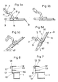
- Fig. 5 eine Prinzipskizze der Schwenklagen des Organs,
- a. in horizontaler Lage mit geöffneter Schienenführung,
- b. in horizontaler Lage mit geschlossener Schienenführung,
- c. in einer geneigten Lage von annähernd vierzig Grad für die Ausgabe von Banknoten,
- d. in einer geneigten Lage von annähernd sechzig Grad für die Ein- und Ausgabe der Objekte in der Kassette,
- Fig. 6 eine Prinzipskizze der Schienenführung in geschlossener Stellung,
- Fig. 7 eine Prinzipskizze der Schienenführung in geöffneter Stellung,
- Fig. 8 eine Prinzipskizze der Lage des blattförmigen Guts auf dem Organ,
- Fig. 9 eine Ansicht von oben auf eine der Kassetten, und
- Fig. 10 eine Prinzipskizze eines Teils einer Vorrichtung mit zwei Einrichtungen und Ausgabeöffnungen, wobei die eine Einrichtung mit blattförmigem Gut beschickt wird und die andere Einrichtung eine Kassette trägt.
- 1 is a perspective, partially sectioned view of a device designed as a cash vault,
- 2 is a plan view of the device with the pivotable member in a horizontal position,
- 3 is a side view of the device with the organ in a horizontal position and dash-dotted in the dispensing position for the objects in the cassette,
- 4 is a front view of the device in viewing direction IV in FIG. 2,
- 5 is a schematic diagram of the pivoting positions of the organ,
- a. in a horizontal position with the rail guide open,
- b. in a horizontal position with closed rail guidance,
- c. in an inclined position of approximately forty degrees for the issuance of banknotes,
- d. in an inclined position of approximately sixty degrees for the input and output of the objects in the cassette,
- 6 is a schematic diagram of the rail guide in the closed position,
- 7 is a schematic diagram of the rail guide in the open position,
- 8 is a schematic diagram of the position of the sheet-like material on the organ,
- Fig. 9 is a top view of one of the cassettes, and
- Fig. 10 is a schematic diagram of part of a device with two devices and dispensing openings, wherein one device is loaded with sheet-like material and the other device carries a cassette.
Die Vorrichtung zum Eingeben, Aufbewahren und Ausgeben von in Kassetten 1 aufbewahrbaren Objekten und von blattförmigem Gut 2 ist als Kassentresor 3 ausgeführt, der mit einem teilweisen Schnitt durch seinen Tresorinnenraum 4 und seine Panzerung 5 in Fig. 1 dargestellt ist. Im Tresorinnenraum 4 werden in einem Kassettenspeicher 9 Kassetten 1 mit z.B. Hartgeld, Banknoten einzeln oder in Bündeln von Fremdwährungen, Sondermünzen, Schmuck oder Wertpapieren, und auf mehreren Rollen eines Rollenspeichers 10 Banknoten 2 als blattförmiges Gut getrennt nach Währung und Werten aufbewahrt. Der Rollenspeicher 10 kann entsprechend der in der nicht zum Stand der Technik gehörenden europäischen Patentanmeldung 88103427.6 beschriebenen Speichereinrichtung ausgeführt sein.The device for entering, storing and dispensing objects that can be stored in
Der Kassentresor 3 ist in der Regel zwischen zwei Kassenschaltern aufgestellt und wird von zwei Kassierern A, B, wie in Fig. 10 angedeutet, gemeinsam bedient. Jeder Kassierer hat auf seiner Seite ein Terminal 11 zur Dateneingabe für eine nicht dargestellte Steuereinrichtung in der Tresortüre 16 für den Kassentresor 3, und eine Ein- und Ausgabeöffnung 12 für die in den Kassetten 1 aufbewahrten Objekte und die Banknoten 2. Die Eingabe der Banknoten 2 erfolgt für beide Kassierer gemeinsam durch eine Eingabeöffnung 13 in der Mitte der Oberfläche des Kassentresors 3. Die in die Öffnung 13 eingelegten Banknoten 2 werden durch einen nicht gezeigten Vereinzelungsmechanismus vereinzelt, mittels einer nicht gezeigten Prüfeinrichtung (namentlich auf Zusammenkleben, ggf. auch auf Echtheit) überprüft, und über einen Förderer 15 im Rollenspeichers 10 gespeichert. Die Kassetten 1 liegen im Kassettenspeicher 9.The
Das Eingeben, Aufbewahren und Ausgeben wird durch die Steuereinrichtung, dessen Terminal 11 in Fig. 1 auf der Oberseite des Kassentresors 3 zu sehen ist, gesteuert, ebenfalls die Zusammenstellung der Banknoten 2 zu ei nem Banknotenbündel 2, ausgehend vom Rollenspeicher 10. Die Banknote bzw. -noten 2 werden vom Rollenspeicher 10 durch den Förderer 15 geholt, und in einem Sammelkasten 19 abgelegt. Aus diesem Sammelkasten 19 wird das Bündel 2, wie in Fig. 10 schematisch dargestellt, je nachdem für welchen Kassierer A oder B es bestimmt ist, mit einem als Schieber 18 ausgebildeten Förderer zu einer rechten oder linken Einrichtung 20 im Tresorinnenraum 4 geschoben. Die Einrichtung 20 übernimmt das Banknotenbündel 2 und schiebt es durch die rechte bzw. linke Öffnung 12 zur Entnahme durch den betreffenden Kassierer.The input, storage and output are controlled by the control device, the
Im folgenden wird die Funktion einer der beiden, gleich aufgebauten Einrichtung 20 beschrieben.The function of one of the two
Der Kassettenspeicher 9 hat für die Kassetten 1 zwei interne Speicherräume 21, eine horizontale Querverschiebeeinrichtung 22 und einen Lift 23 zum vertikalen Transport. Eine durch die Steuereinrichtung ausgewählte Kassette 1 wird über die Querverschiebeeinrichtung 22 von ihrem Platz in einem der beiden Speicherräume 21 zum Lift 23 geschoben, von diesem zur Einrichtung 20 gehoben, und wie unten beschrieben, von dieser übernommen und anschließend durch die Öffnung 12 transportiert, wo ihr Inhalt durch den Kassierer B entnommen wird. Anschließend wird die Kassette 1 entweder wieder z. B. mit Banknoten 2, oder -bündeln, Hartgeld etc. gefüllt, oder leer durch die Öffnung 12 zurückgezogen und auf ihren ursprünglichen Platz in einem der Speicherräume 21 zurückgeführt.The cassette storage 9 has two
Die für die Ausgabe von Banknotenbündeln 2, sowie für die Aufnahme und Verschiebung der Kassette 1 verwendete Einrichtung 20; ist in einer Draufsicht in Fig. 2 und in je einer Seitenanschicht in Fig. 3 bzw. 4 gezeigt. Die Einrichtung 20 ist mit einem rechten und linken Flansch 25 und 26 an einem aus dem Tresorinnenraum 4 auszeihbaren Träger 8 (Fig. 1) befestigt.The
Damit die Banknotenbündel 2, sowie die Kassette 1 durch die aus Sicherheitsgründen klein gehaltende Öffnung 12 geführt werden können und dort griffbereit für den Kassierer liegen, werden die Banknotenbündel 2 und die Kassetten 1 über ein schwenkbares plattenförmiges Organ 29 der Ein richtung 20 direkt unter die Öffnung 12 gebracht, und anschließend durch sie hindurchgeschoben. Die Öffnung 12 ist nur während der Ausgabe geöffnet. Die übrige Zeit ist sie mit einem Schieber 27 verschlossen. Die Schwenkung des Organs 29 erfolgt um eine Schwenkachse 30 mittels je zweier Kurbeln 31 und je zweier Winkelhebel 32, wobei die beiden Kurbeln 31 drehfest an einer Antriebswelle 33 befestigt sind. Die Achse 33 wird durch einen am Flansch 26 befestigten Motor 35 gedreht. Wie in Fig. 4 gezeigt, liegt die Antriebswelle 33 oberhalb und parallel zur Schwenkachse 30, und ist durch je ein Lager 37 und 39 in den Flanschen 25 und 26 der Einrichtung 20 gelagert. Die Achse 33 und der Motor 35 sind über eine Kupplung 40 miteinander verbunden. Jeder der beiden anderen Winkelhebel 32 ist am Ende der Kurbel 31 und annähernd in der Mitte je eines nach oben gebogenen äußeren Seitenrandes 41 bzw 42 des Organs 29 durch in ihn eingepreßte Bolzen 43 und 44 schwenkbar gelagert. Die Bolzen 43 bzw. 44 sind durch Sprengringe am Herausrutschen aus einer Bohrung 47 der Kurbel 31 bzw. den Rändern 41 und 42 gesichert. Die Schwenkachse 30 liegt horizontal, und ist ebenfalls an jedem der Flansche 25 und 26 durch ein Lager 45 bzw. 46 drehbar gehalten. Das Organ 29 ist durch je ein Lager 49 und 50 in der rückwärtigen Verlängerung seiner Ränder 41 und 42 schwenkbar auf der Achse 30 gelagert. Die Schwenkachse 30 ist somit frei drehbar in den Flanschen 25 und 26 gelagert, und außerdem das Organ 29 frei drehbar auf der Schwenkachse 30. Die Lager 45 und 49, sowie 46 und 50 sind durch je eine Distanzbuchse 51 und 52 voneinander distanziert. Die Distanzbuchsen 51 und 52 distanzieren und positionieren das Organ 29 seitlich zu den beiden Flanschen 25 und 26.So that the bundle of
Die Kurbeln 31 haben an dem einen Ende die Bohrung 47 und an dem anderen eine Bohrung 48. Die Bohrung 47 nimmt den Bolzen 43 auf und in der Bohrung 48 steckt die Antriebswelle 33. Radial zur Bohrung 48 an deren einem Auslauf befindet sich in der Oberfläche eine zur Bohrung 48 hin freie, aber radial nach außen begrenzte Kerbe. In dieser Kerbe liegt ein durch die Antriebswelle 33 gesteckter Stift 54, wie in Fig. 3 und 4 angedeutet. Der Stift 54 dient zur Kraftübertragung von der Antriebswelle 33 auf die Kurbel 31. Das Herauswandern des Stifts 54 aus der Kerbe der Kurbel 31 wird durch einen in einer Nut der Antriebswelle 33 sitzenden Sprengring 55 verhindert, der gegen die Kurbel 31 drückt ; der radiale Abschluß der Kerbe verunmöglicht ein radiales Herausrutschen des Stifts 54.The
Jeder Winkelhebel 32 besitzt annähernd in seiner Mitte ein nach oben gerichtetes Knie 56, wobei die Knieschenkel in der Kniekehle einen Winkel von annähernd einhunderdreißig Grad bilden. Ein Knieschenkel ist, wie oben beschrieben, mit einem Bolzen 43 drehbar an der Kurbel 31, und der andere über einen weiteren Bolzen 44 drehbar und mit einem Sprengring gesichert, annähernd in der Mitte des Randes 41 bzw. 42 des Organs 29 gelagert. Vom Ende des Winkelhebels 32, welches mit dem Bolzen 44 im Organ 29 gelagert ist, erstreckt sich annähernd unter einem rechten Winkel in Richtung des Knies 56 ein Schenkel 57.Each
Im Abstand von einigen Millimetern von den Lagern 49 und 50 innerhalb des Organs 29 sitzen auf der Schwenkachse 30 je zwei mit ihr drehfest verstiftete Zahnriemenräder 60, 61, 62 und 63. Die Verstiftung erfolgt analog zur Kurbel 31 auf der Antriebswelle 33. Die Zahnriemenräder 60 bis 63 werden über die Schwenkachse 30 durch einen Motor 65 angetrieben.At a distance of a few millimeters from the
An den beiden Rändern der der Schwenkachse 30 gegenüberliegenden Seite des Organs 29, befinden sich, durch je zwei Lagerböcke gehalten, je eine Achse 70 und 71 mit je zwei Zahnriemenrädern 72 und 73. Die Zahnriemenräder 60, 61 bzw. 62, 63 und die Zahnriemenräder 72 bzw. 73 sind durch je zwei Zahnriemenpaare 66 bzw. 67 verbunden. Die vier Zahnriemen 66 laufen über die Oberseite 75 des Organs 29 hin und über die Unterseite 76 wieder zurück.On the two edges of the side of the
Auf der Unterseite 76 ist ein Schieber 77 an seinen Außenkanten jeweils an einem der Zahnriemenpaare 66 bzw. 67 derart angeklemmt, daß er parallel zur Schwenkachse 30 über die Unterseite 76 verschiebbar ist. Über etwa achtzig Prozent der Breite des Schiebers 77 ersteckt sich an der der Schwenkachse 30 zugewandten Seite symmetrisch zur Seitenmitte ein abgewinkelter Ansatz 79, der dazu dient die Kassette 1 durch die Öffnung 12 zu schieben. Auf gleicher Höhe mit dem Ansatz 79 an den Außenkanten des Schiebers 77 befindet sich je ein abgewinkelter Greifer 81. In jeden der Greifer 81 greift eine Öse 82 am unteren Außenrand der Kassette 1, wie in Fig. 9 dargestellt, zum Zurückziehen der Kassette 1.On the
Über die Schwenkachse 30 ist eine innen hohle Welle 84 geschoben. An jeder Seite der Welle 84 befindet sich auf der Schwenkachse 30 je eine Distanzscheibe 85 bzw. 87. In ihrer Lage ist die Welle 84 durch einen Sprengring 90 in einer Nut der Schwenkachse 30 an der zum Zahnriemenrad 62 zeigenden Seite fixiert, und zur gegenüberliegenden Seite hin stößt die Distanzscheibe 85 direkt an das Zahnriemenrad 61 an. Die Welle 84 hat an der an die Distanzscheibe 85 anschließenden Seite ein Zahnriemenrad 91 und ein Zahnrad 92 und hieran anschließend eine Distanzbuche 93 und ein Zahnriemenrad 94 abwechselnd in dreimaliger Folge.An internally
Die drei Zahnriemenräder 94 liegen annähernd symmetrisch zur Mitte des Organs 29. Über sie laufen auf der Ober- und Unterseite 75 und 76 drei Zahnriemen 101. An der der Schwenkachse 30 entgegengesetzten Seite des Organs 29 werden die Zahnriemen 101 durch drei Zahnriemenräder 102 auf einer Welle 99 umgelenkt.The three
Über der Oberseite 75 befindet sich ein Niederhalter 103. Der Niederhalter 103 hat einen Bügel 104, eine zur Schwenkachse 30 parallele Welle 105 mit einem analog zu Kurbel 31 verstifteten Zahnriemenrad 100 und drei elastische Transportrollen 109, die beim weiter unten beschriebenen Schwenkvorgang direkt über den Zahnriemen 101 zuliegen kommen, und ein Federblech 110. Das Federblech 110 ist an der von der Schwenkachse 30 wegweisenden Seite des Bügels 104 angeschweißt. Der Bügel 104 ist an zwei Schienen 111 annähernd in deren Mitte angeschraubt. Die Schienen 111 sind mittels je eines Lagers 112 schwenkbar an einer Achse 113 gelagert, die auf gleicher Höhe wie die Schwenkachse 30 und parallel zu ihr starr mit den Rändern 41 und 42 verbunden ist. Am anderen Ende der Schiene 111 ist die Welle 105 in je einem Lager 115 gehalten. Das Zahnriemenrad 100 befindet sich neben einer der Schienen 111 innerhalb des Niederhalters 103. Der Bügel 104 bildet mit jeder Schiene 111 einen Winkel von annähernd dreißig Grad, wobei der Winkelscheitel zur Welle 105 zeigt. Auf der Achse 113 läuft ein Zahnriemenrad 97 und ein Zahnrad 96, die an einer Stirnseite durch eine der Schienen 111 und auf der anderen Seite durch einen Spannring 117 am seitlichen Auswandern gehindert werden. Das Zahnrad 92 auf der Welle 84 treibt direkt das Zahnrad 96 und das Zahnriemenrad 97 an. Über das Zahnriemenrad 97 läuft ein Zahnriemen 119 zum Zahnriemenrad 100. Die Übertragung über die Zahnräder 92, 96, das Zahnriemenrad 97, den Zahnriemen 119 und das Zahnriemenrad 100 auf die Transportrollen 109 dient dazu, die Transportrollen 109 mit der gleichen Umfangsgeschwindigkeit wie die Zahnriemen 101 laufen zu lassen. Zwischen der Oberkante des Bügels 104 und des Organs 29 ist je eine Zugfeder 120 im Abstand von einigen Millimetern von der Schiene 111 angeordnet, die den Niederhalter 103 zum Organ 29 hinzieht. Ebenfalls an der Oberkante des Bügels 104 ist ein Kunststoffband 121 befestigt, das den Niederhalter 103 bei horizontaler Lage des Organs 29 gegen die Kraft der beiden Federn 120 vom Organ 29 einige Millimeter, wie in Fig. 3 gezeigt, distanziert.A hold-down
An der Außenseite der Ränder 41 bzw. 42 befindet sich je eine Schienenführung 122 für die Kassette 1. Die beiden Schienenführungen 122 sind spiegelbildlich zueinander. Sie sind so geformt, daß sie an ihrem an der Unterseite 76 des Organs 29 liegenden Teil je einen Ansatz 123 haben, wobei die beiden Ansätze parallel zum Organ 29 aufeinander hinzeigen. Jede der Schienenführungen 122 wird durch je eine Feder 125 an den betreffenden Rand 41, 42 gezogen. An der Oberkante der Schieneführung 122 zeigt je ein Ansatz 129 vom Organ 29 weg. Ebenfalls an der Oberkante der Schienenführung 122 ist in deren Längsrichtung je ein stiftförmiger Fortsatz 130 als Achse ausgebildet, die in einem Kunststofflagerbock 131, bevorzugt aus Delrin, steckt. Die Kunststoffböcke 131 sind an den Rändern 41 und 42 angeschraubt. Der Bolzen 44 des Winkelhebels 32 in den Rändern 41 bzw. 42 greift durch je eine Öffnung der Schienenführungen 122 hindurch. Eine Schwenkbewegung jeder Schienenführung 122 wird somit durch die Bolzen 44 nicht behindert.There is a
Bei den Kassetten 1 handelt es sich um ein innen hohles rechtwinkliges Parallepiped, das an einer seiner Längsseiten offen ist. Wie in Fig. 9 dargestellt, ist an der der offenen Längsseite gegenüberliegenden Seite in der Nähe der Kante zu den Breitseiten und in unmittelbarer Nähe zu einer der Deckflächen je eine der Ösen 82 gebildet. Anschließend an jede der Ösen 82 läuft entlang der jeweiligen Seitenfläche ein Vorsprung 127. Die Kassette 1 wird, wie in Fig. 6 und 7 gezeigt, durch den Ansatz 123 der Schienenführung 122 an ihrem Vorsprung 127 gehalten, ergriffen bzw. gleitet auf ihm, wie weiter unten beschrieben.The
Im folgenden werden die Bewegungsabläufe näher beschrieben.The movement sequences are described in more detail below.
Zur Aufnahme des Banknotenbündels 2 aus dem Sammelkasten 19 befindet sich das schwenkbare Organ 29 in horizontaler Lage, wie in Fig. 5b und Fig. 10, dargestellt. In der horizontalen Lage liegt der Drehpunkt mit dem Bolzen 43 des Winkelhebels 32 und der Kurbel 31 geringfügig über der Verbindungslinie der Mitte der Antriebswelle 33 und der Mitte des Bolzens 44, d. h. der Schwenkmechanismus mit Kurbel 31 und Winkelhebel 32 hat seinen unteren Totpunkt gerade noch nicht erreicht. Der Niederhalter 103 ist durch das Kunststoffband 121 vom Organ 29 abgehoben, damit das durch den Schieber 18 aus dem Sammelkasten 19 auf die Oberseite 75 des Organs 29 geschobene Banknotenbündel 2 nicht behindert wird. Ein Zahnriemen 132 ist über eine nicht gezeigte Rutschkupplung mit dem Förderer 18 verbunden, und treibt über das Zahnriemenrad 91 die Achse 84 an. Die Achse 84 treibt über die drei Zahnriemenräder 94 die Zahnriemen 101, und über das Zahnrad 92 das Zahnrad 96 mit dem Zahnriemenrad 97 und die Achse 113 an. Die Fördergeschwindigkeit des Banknotenbündels 2 stimmt mit der Geschwindigkeit der Zahnriemen 101 und der Umfangsgeschwindigkeit der drei elastischen Rollen 109 überein. Sind etwa zwanzig Prozent der Banknotenlänge unter den Transportrollen 109 durchgelaufen, wird die Bewegung angehalten. Durch den Motor 35, die Antriebswelle 33, die Kurbel 31 und den Winkelhebel 32 wird das Organ 29 um die Schwenkachse 30 nach oben zur Achse 33 hin geschwenkt. Nach einer Schwenkung von annähernd zehn Grad aus der Horizontalen, berührt der Niederhalter 103 mit seinem Federblech 110 das auf dem Organ 29 liegende Banknotenbündel 2. Nach weiteren annähernd zehn Grad drücken auch die Transportrollen 109 auf das Banknotenbündel 2. Das Banknotenbündel 2 ist jetzt fest eingeklemmt und die Schwenkung wird bis zu einem Winkel von vierzig Grad aus der Horizontalen, wie in Fig. 5c gezeigt, fortgesetzt, bis das Banknotenbündel 2 direkt unter der Öffnung 12 ist. Der Antrieb über den Zahnriemen 132 wird wieder in Gang gesetzt und das Banknotenbündel 2 durch die Öffung 12 geschoben, bis es gerade die Transportrollen 109 passiert hat, aber noch einwandfrei durch das Federblech 110 des Niederhalters 103 gehalten wird. Das Banknotenbündel 2 ragt nun in guter Greiflage für den Kassierer aus der Öffnung 12, und kann entnommen werden. In dieser Schräglage wird das Organ 29 nur durch die Kraft des Motors 35 gehalten. Das ist möglich, da das Gewicht des Banknotenbündels 2 gering ist und während der Entnahme durch die Öffnung 12 auch keine Kräfte auf das Organ 29 ausgeübt werden. Die Entnahme des Banknotenbündels 2 wird, wie in Fig. 10 dargestellt, durch einen elektrooptischen Sensor 133 in der Öffnung 12 festgestellt. Nach der Entnahme wird das Organ 29 wieder in die horizontale Lage, wie sie in Fig. 5b gezeigt ist, zurückgeschwenkt. Die Einrichtung 20 ist bereit, wieder Banknotenbündel 2 aufzunehmen.To receive the bundle of
Zur Aufnahme einer durch die Steuereinrichtung ausgewählte Kassette 1 wird die Kurbel 31 um etwa sieben Grad über die in Fig. 5b gezeigte Stellung hinaus in die in Fig. 5a gezeigte Stellung nach unten gedreht. Das Organ 29 befindet sich, da die Drehung um den unteren Totpunkt herum erfolgt, immer noch in horizontaler Lage. In dieser horizontalen Lage liegt der Drehpunkt mit dem Bolzen 43 des Winkelhebels 32 und der Kurbel 31 geringfügig, wie in Fig. 5a gezeigt, unter der Verbindungslinie der Mitte der Antriebswelle 33 und der Mitte des Bolzens 44, d. h. der Schwenkmechanismus mit Kurbel 31 und Winkelhebel 32 hat seinen unteren Totpunkt gerade überschritten. Der Schenkel 57 ist jedoch mit seinem freien Ende durch die zusätzliche Drehung nach oben bewegt worden, und drückt mit seinem Ende den Ansatz 129 nach oben. Hierdurch wird die Schienenführung 122 um ihre Achse, gebildet aus den Fortsätzen 130, die in den Blöcken 131 gelagert sind, geschwenkt, d. h. der Ansatz 123 wird, wie in Fig. 6 dargestellt nach außen gedrückt. Der Schieber 77 auf der Unterseite 76 des Organs 29 befindet sich in einer Stellung nahe der Schwenkachse 30. Die durch die Steuereinrichtung ausgewählte Kassette 1 wird durch die Querverschiebeeinrichtung 22 zum Lift 23 geschoben, und durch diesen unter das Organ 29 gehoben. Jede der Kassetten 1 hat, wie in Fig. 9 gezeigt und oben beschrieben, in der Nähe ihres äußeren unteren Randes zwei Ösen 82. Diese beiden Ösen 82 rasten in die Greifer 81 des Schiebers 77 ein. Der Motor 35 dreht beide Kurbeln 31 nach oben, der Schenkel 57 verläßt den Fortsatz 130. Jede der Schienenführungen 122 wird, wie in Fig. 6 ge zeigt, durch die Feder 125 gegen den Rand 41 bzw. 42 gezogen, wodurch die Kassette 1 mit ihrem seitlichen Vorsprung 127 durch den Ansatz 123 der Schienenführung 122 am Organ 29 gehalten ist. Da diese Drehung unmittelbar um den unteren Totpunkt des Schwenkmechanismusses erfolgt, hat das Organ 29 bis jetzt keine Schwenkung durchgeführt. Eine Schwenkung setzt nun langsam ein und der Motor 35 dreht weiter bis bei einer Neigung des Organs 29 von etwa sechzig Grad zur Horizontalen der obere Totpunkt überschritten ist, und die Kniekehle 56 des Winkelhebels 32 auf der Antriebswelle 33, wie in Fig. 5d gezeigt, liegt. In dieser Position befindet sich die Kassette 1 unter der Öffnung 12. Die Öffnung 12 wird durch den Schieber 27 freigegeben und die Kassette 1 auf den Schienenführung 122 gleitend durch die Greifer 81 und den Ansatz 79 am Schieber 77 vom Motor 65 über die Welle 30, die Zahnriemenräder 60 bis 63 und die Zahnriemen 119 verschoben. Unterhalb der Öffnung 12 sind weitere Schienen 134 in der Öffnung 12 vorhanden, in denen der Vorsprung 127 der Kassette 1 weiter gleitet, sobald er über die Schienenführungen 122 hinausragt. Die Verschiebung des Schiebers 77 wird gestoppt, sobald die Kassette 1 in die Nähe des oberern Rands des Organs 29 kommt. Die Kassette 1 steht jetzt über die Öffnung 12 hinaus und ihr Inhalt wird durch den Kassierer entnommen. Das Gewicht der Kassette 1, des Organs 29, und eine ev. Belastung durch den Kassierer bei der Entnahme der in der Kassette 1 aufbewahrten Objekte, drücken die Kniekehle 56 nur noch stärker gegen die Antriebswelle 33; das Organ 29 bleibt selbstfixiert in dieser Lage. Neu gefüllt oder auch leer wird die gleiche Kassette 1, sie kann nicht entnommen werden, wieder zurückgezogen, der Schieber 27 geschlossen, und das Organ 29 in die in Fig. 5a gezeigte horizontale Position zurückgeschwenkt, wobei die Schienenführungen 122 wieder geöffnet werden. Der Lift 23 übernimmt die Kassette 1, um sie über die Querverschiebeeinrichtung 22 im Speicherraum 21 des Speicher 5 abzulegen. Das schwenkbare Organ 29 und auch der Kassettenspeicher 9 sind so ausgelegt, daß Kassetten 1 mit einfacher und doppelter Füllhöhe verwendbar sind.To receive a
Alle Ein- und Ausgaben der Kassetten 1 und von Banknoten (2), sowie u. a. ihr Wert werden mit Bankkundenangaben in einem nicht gezeigten Journaldrucker in der Tresortüre 16 ausgedruckt.All inputs and outputs of
Die Verschiebung der u. U. schweren Kassetten 1 durch die Öffnung 12 und auch ihre Aufnahme vom Lift 23 in unmittelbarer Nähe jeweils eines Totpunktes der beiden Kurbeln 31 und 32 hat den Vorteil, daß Haltekräfte für den Motor 35 nahezu vernachlässigt werden können und der Bewegungsablauf des Organs 29 aus dem Stillstand ohne Ruck beginnt.The shift of u. U.
Die Befestigung der Zahnriemenräder 61 bis 63, des Zahnrads 96 mit dem Zahnriemenrad 97, sowie der Kurbel 31 auf der Achse 33 mit Stift und Sprengring hat sich in der Montage bewährt, könnte aber auch anders z. B. auch mittels Splinte durchgeführt werden.The attachment of the toothed belt wheels 61 to 63, the
Der leicht angehobene Niederhalter 103 beim Einschieben des Banknotenbündels 2 aus dem Sammelkasten 19 auf die Oberseite 75 des Organs 29 hat sich ebenfalls bewährt; unter entsprechender Dimensionierung des Durchmessers der Transportrollen 109 und der Kraft der Feder 120 könnte auf die Anhebung jedoch verzichtet werden.The slightly raised hold-down
Anstelle der drei Zahnriemen 101, bzw. der Zahnriemenpaare 67 und 66 können bei geringer konstruktiver Anpassung auch Bänder mit angepaßter Breite verwendet werden.Instead of the three
Claims (15)
Applications Claiming Priority (2)
| Application Number | Priority Date | Filing Date | Title |
|---|---|---|---|
| CH911/88A CH674396A5 (en) | 1988-03-10 | 1988-03-10 | |
| CH911/88 | 1988-03-10 |
Publications (2)
| Publication Number | Publication Date |
|---|---|
| EP0331896A2 true EP0331896A2 (en) | 1989-09-13 |
| EP0331896A3 EP0331896A3 (en) | 1989-12-27 |
Family
ID=4198040
Family Applications (1)
| Application Number | Title | Priority Date | Filing Date |
|---|---|---|---|
| EP89101531A Ceased EP0331896A3 (en) | 1988-03-10 | 1989-01-30 | Inserting, storing and dispensing device for objects and sheetlike articles to be stored in cassettes |
Country Status (4)
| Country | Link |
|---|---|
| US (1) | US5016546A (en) |
| EP (1) | EP0331896A3 (en) |
| JP (1) | JPH01267791A (en) |
| CH (1) | CH674396A5 (en) |
Families Citing this family (12)
| Publication number | Priority date | Publication date | Assignee | Title |
|---|---|---|---|---|
| IT1256495B (en) * | 1992-12-30 | 1995-12-07 | Giuseppe Ezio Fumanelli | PROCEDURE AND DEVICE FOR THE AUTOMATED RECEPTION AND DISPENSING OF BANKNOTES AND VALUES |
| DE9314341U1 (en) * | 1993-09-23 | 1993-11-04 | Ascom Autelca AG, Gümligen, Bern | Cash safe with an optional safe control unit to be operated by two cashiers |
| US5722332A (en) * | 1995-12-28 | 1998-03-03 | M.I.B. Elettronica S.R.L. | Apparatus and process for conducting deposit and drawing operations of banknotes and valuables |
| US5938072A (en) * | 1997-09-16 | 1999-08-17 | Magner Corporation | Rolled coin dispenser |
| US6332099B1 (en) | 1998-03-11 | 2001-12-18 | Bally Gaming, Inc. | Gaming machine payout controlling system and method |
| US6014594A (en) | 1998-03-11 | 2000-01-11 | Bally Gaming, Inc. | Gaming machine payout dispensing system with on escrow area and locks |
| US6293867B1 (en) | 1998-03-11 | 2001-09-25 | Bally Gaming, Inc. | Gaming machine payout system and method |
| AU771924B2 (en) | 1999-04-23 | 2004-04-08 | Alliance Gaming Corporation | A system and method for securely storing and controlling the dispensing of a payout |
| US20030014667A1 (en) * | 2001-07-16 | 2003-01-16 | Andrei Kolichtchak | Buffer overflow attack detection and suppression |
| KR101094627B1 (en) * | 2005-01-04 | 2011-12-15 | 엘지엔시스(주) | Customer access apparatus for media dispenser |
| US9865118B2 (en) * | 2012-07-31 | 2018-01-09 | Ncr Corporation | Cassette replenishment |
| US10957445B2 (en) | 2017-10-05 | 2021-03-23 | Hill-Rom Services, Inc. | Caregiver and staff information system |
Citations (2)
| Publication number | Priority date | Publication date | Assignee | Title |
|---|---|---|---|---|
| FR2101742A5 (en) * | 1970-07-17 | 1972-03-31 | Omron Tateisi Electronics Co | |
| EP0182137A1 (en) * | 1984-11-05 | 1986-05-28 | Autelca Ag | Safe for a till |
Family Cites Families (15)
| Publication number | Priority date | Publication date | Assignee | Title |
|---|---|---|---|---|
| US1506491A (en) * | 1922-05-12 | 1924-08-26 | kline | |
| US2770516A (en) * | 1953-05-11 | 1956-11-13 | Mosler Safe Co | Depositing machines |
| US2963333A (en) * | 1957-01-14 | 1960-12-06 | Mestre Luis | Depositing machine |
| US3078789A (en) * | 1960-03-02 | 1963-02-26 | Bernard F Mcgee | Depositories |
| US3683826A (en) * | 1970-11-13 | 1972-08-15 | Shaw Walker Co | Drawer depository |
| US3836980A (en) * | 1973-05-03 | 1974-09-17 | Diebold Inc | Remote depository construction |
| US4164179A (en) * | 1974-10-21 | 1979-08-14 | Docutel Corporation | Depository System |
| DE2805252A1 (en) * | 1978-02-08 | 1979-08-09 | Hauni Werke Koerber & Co Kg | BARRIER UNIT TO RECEIVE BANKNOTES |
| US4308804A (en) * | 1979-11-08 | 1982-01-05 | Honeywell Information Systems Inc. | Automatic cash depository |
| JPS57130189A (en) * | 1981-02-02 | 1982-08-12 | Laurel Bank Machine Co | Paper money storage box with reject pool section for paper money clearing machine |
| US4483255A (en) * | 1982-09-30 | 1984-11-20 | Collier Safe Co., Inc. | Night depository |
| GB2131082A (en) * | 1982-11-19 | 1984-06-13 | De La Rue Syst | Secure containers |
| GB2156904B (en) * | 1984-03-31 | 1987-05-07 | Burroughs Corp | Autoteller including tilt sensitive |
| DE3412424C1 (en) * | 1984-04-03 | 1985-06-27 | Nixdorf Computer Ag, 4790 Paderborn | Container for holding notes |
| US4726474A (en) * | 1984-05-08 | 1988-02-23 | Laurel Bank Machines Co., Ltd. | Circulating-type bill depositing and disbursing machine |
-
1988
- 1988-03-10 CH CH911/88A patent/CH674396A5/de not_active IP Right Cessation
-
1989
- 1989-01-30 EP EP89101531A patent/EP0331896A3/en not_active Ceased
- 1989-02-17 US US07/311,734 patent/US5016546A/en not_active Expired - Fee Related
- 1989-03-09 JP JP1055276A patent/JPH01267791A/en active Pending
Patent Citations (2)
| Publication number | Priority date | Publication date | Assignee | Title |
|---|---|---|---|---|
| FR2101742A5 (en) * | 1970-07-17 | 1972-03-31 | Omron Tateisi Electronics Co | |
| EP0182137A1 (en) * | 1984-11-05 | 1986-05-28 | Autelca Ag | Safe for a till |
Also Published As
| Publication number | Publication date |
|---|---|
| CH674396A5 (en) | 1990-05-31 |
| US5016546A (en) | 1991-05-21 |
| JPH01267791A (en) | 1989-10-25 |
| EP0331896A3 (en) | 1989-12-27 |
Similar Documents
| Publication | Publication Date | Title |
|---|---|---|
| DE3303809C2 (en) | Carrying device for banknotes stacked in a banknote container | |
| DE2949344C2 (en) | Security cassette for use in bank note machines | |
| DE3516384C2 (en) | ||
| DE69610366T2 (en) | Music stacker | |
| DE2506195A1 (en) | BANKNOTE DISPENSER | |
| EP0182137A1 (en) | Safe for a till | |
| DE68902578T2 (en) | PNEUMATIC CASH CONVEYORS AND RIFLES FOR USE IN SUCH SYSTEMS. | |
| DE69510586T2 (en) | Transaction facility with parts for storing sheets | |
| DE3736263C2 (en) | ||
| DE69013704T2 (en) | Automatic goods dispensers and methods for dispensing goods. | |
| DE2907276A1 (en) | DEVICE FOR DISTRIBUTION OF BANKNOTES | |
| EP0331896A2 (en) | Inserting, storing and dispensing device for objects and sheetlike articles to be stored in cassettes | |
| EP0063691B1 (en) | Carrier and station for tube mail | |
| DE3517848C2 (en) | ||
| DE3736697A1 (en) | DEVICE WITH A BANKNOTE MEMORY FOR A MACHINE FOR ACCEPTING AND DISPENSING BANKNOTES | |
| DE10147134B4 (en) | Stacking straps with switched deposit cassettes | |
| DE3735648A1 (en) | BANKNOTE TRANSPORT DEVICE IN A MACHINE FOR ACCEPTING AND DISPENSING BANKNOTES | |
| DE3519635A1 (en) | BANKNOTE INPUT AND OUTPUT MECHANISM ASSOCIATED WITH AT LEAST ONE INPUT AND OUTPUT OPENING OF A BANKNOTE ACCEPTANCE AND OUTPUT MACHINE | |
| DE69204202T2 (en) | Device for treating leaves. | |
| DE69815487T2 (en) | Improvements to a cash dispenser | |
| DE69715270T2 (en) | A bill handling machine | |
| DE4112340A1 (en) | BANKNOTE HANDLING DEVICE | |
| EP0472673B1 (en) | Container for receiving bank notes in a bank note dispensing device | |
| DE2816371A1 (en) | Banknote assembly and dispensing machine - has magazines with separator mechanisms connected to storage tracks | |
| DE2815586A1 (en) | SINGLE MONEY DISPENSER |
Legal Events
| Date | Code | Title | Description |
|---|---|---|---|
| PUAI | Public reference made under article 153(3) epc to a published international application that has entered the european phase |
Free format text: ORIGINAL CODE: 0009012 |
|
| AK | Designated contracting states |
Kind code of ref document: A2 Designated state(s): AT BE DE ES FR GB IT NL SE |
|
| PUAL | Search report despatched |
Free format text: ORIGINAL CODE: 0009013 |
|
| AK | Designated contracting states |
Kind code of ref document: A3 Designated state(s): AT BE DE ES FR GB IT NL SE |
|
| 17P | Request for examination filed |
Effective date: 19900521 |
|
| 17Q | First examination report despatched |
Effective date: 19920319 |
|
| STAA | Information on the status of an ep patent application or granted ep patent |
Free format text: STATUS: THE APPLICATION HAS BEEN REFUSED |
|
| 18R | Application refused |
Effective date: 19930617 |