EP0331607B1 - Oil separator - Google Patents
Oil separator Download PDFInfo
- Publication number
- EP0331607B1 EP0331607B1 EP89630040A EP89630040A EP0331607B1 EP 0331607 B1 EP0331607 B1 EP 0331607B1 EP 89630040 A EP89630040 A EP 89630040A EP 89630040 A EP89630040 A EP 89630040A EP 0331607 B1 EP0331607 B1 EP 0331607B1
- Authority
- EP
- European Patent Office
- Prior art keywords
- chamber
- oil
- compressor discharge
- discharge
- compressor
- Prior art date
- Legal status (The legal status is an assumption and is not a legal conclusion. Google has not performed a legal analysis and makes no representation as to the accuracy of the status listed.)
- Expired - Lifetime
Links
Images


Classifications
-
- F—MECHANICAL ENGINEERING; LIGHTING; HEATING; WEAPONS; BLASTING
- F25—REFRIGERATION OR COOLING; COMBINED HEATING AND REFRIGERATION SYSTEMS; HEAT PUMP SYSTEMS; MANUFACTURE OR STORAGE OF ICE; LIQUEFACTION SOLIDIFICATION OF GASES
- F25B—REFRIGERATION MACHINES, PLANTS OR SYSTEMS; COMBINED HEATING AND REFRIGERATION SYSTEMS; HEAT PUMP SYSTEMS
- F25B43/00—Arrangements for separating or purifying gases or liquids; Arrangements for vaporising the residuum of liquid refrigerant, e.g. by heat
- F25B43/02—Arrangements for separating or purifying gases or liquids; Arrangements for vaporising the residuum of liquid refrigerant, e.g. by heat for separating lubricants from the refrigerant
-
- B—PERFORMING OPERATIONS; TRANSPORTING
- B01—PHYSICAL OR CHEMICAL PROCESSES OR APPARATUS IN GENERAL
- B01D—SEPARATION
- B01D46/00—Filters or filtering processes specially modified for separating dispersed particles from gases or vapours
- B01D46/10—Particle separators, e.g. dust precipitators, using filter plates, sheets or pads having plane surfaces
- B01D46/12—Particle separators, e.g. dust precipitators, using filter plates, sheets or pads having plane surfaces in multiple arrangements
-
- B—PERFORMING OPERATIONS; TRANSPORTING
- B01—PHYSICAL OR CHEMICAL PROCESSES OR APPARATUS IN GENERAL
- B01D—SEPARATION
- B01D50/00—Combinations of methods or devices for separating particles from gases or vapours
- B01D50/20—Combinations of devices covered by groups B01D45/00 and B01D46/00
Definitions
- the present invention relates generally to an oil separator for a horizontal screw compressor and to a method for removing oil from the discharge of the screw compressor.
- Screw compressors employed in refrigeration applications commonly use oil for sealing, lubricating and cooling.
- the oil is injected into the working chamber of the compressor and thus into the refrigerant gas being compressed.
- the compressor discharge ordinarily contains oil entrained in the compressed refrigerant gas.
- the presence of oil interferes with the heat exchange function of the refrigeration system and otherwise degrades the efficiency of the system.
- the amount of oil carried over is kept as low as possible in order to minimize the degrading of the heat transfer surfaces, to minimize the return of oil from remote locations in the system and to keep a sufficient oil supply in the oil sump for sealing, lubricating and cooling needs.
- the oil removal or separation ordinarily takes place at a convenient place between the compressor discharge and the condenser.
- EP-A-0 038 018 there is described a method for removing oil from the discharge of a compressor and an oil separator for a horizontal screw compressor comprising a generally cylindrical member having an opening for receiving the rotor assembly of the screw compressor.
- Discharge deflector means direct the discharge from the compressor generally downwardly whereby the discharge is diverted at least 90° and is caused to impinge upon a surface to thereby deposit entrained oil thereon.
- the impinging compressor discharge flow is caused to be diverted approximately 180° and then passes serially through a divider plate means and through demister means located in the cylindrical member to be directed out of the separator in a nearly oil-free state.
- the oll separator of the invention is characterized by the features set forth in claim 1 and the invention provides a method for removing oil from the compressor discharge according to claim 7.
- Advantageous embodiments of the invention are claimed in the subclaims.
- a plurality of flow direction changes in combination with a discharge deflector, demisters and a coalescer to remove and collect oil entrained in the refrigerant gas. Except for oil removed in the coalescer, all of the separated oil drains directly into the oil sump.
- the refrigerant gas and entrained oil is subjected to at least two impingements with a resulting change in direction to inertially remove as much oil as possible prior to reaching the demisters where the amount of oll removal has a direct, temporary effect on the demisters and their flow resistances as the entrained oll impinges, collects and drains to the sump.
- the discharge from a horizontal screw compressor is directed radially and in a generally downward direction where it impinges upon the surface of the oil and/or a discharge deflector.
- the discharge deflector is generally in the shape of an arcuate trough about 45°-50° in extent. The arcuate portion is spaced from the compressor discharge and the discharge deflector surrounds the compressor discharge. Impingement of the discharge flow with the surface of the oil in the trough and/or the discharge deflector produces a directional flow change with a portion of the oil collecting in the oil pool and/or on the trough surface due to inertial forces as the flow direction changes.
- the trough guides the flow upwardly along its inner surface so that it impinges upon the lower surface of the divider plate which is titled a few degrees from horizontal such that oil striking and collecting on the lower surface flows along the tilted surface and drains back to the sump by gravity.
- the discharge flow changes direction due to its impingement upon the lower surface and impinges upon and is diverted by a baffle plate extending downwardly from the divider plate which also collects oil impinging thereon due to inertia.
- the discharge flow then serially passes through two demister pads, impinges upon the end of the oil separator housing and is diverted upward. The flow then turns to enter the coalescer completing a 180° change of direction after passing through the demisters.
- the flow passes through the walls of the coalescer leaving any entrained oil trapped in the coalescing media of the element.
- the coalesced oil gathers on the outside diameter of the coalescer and drops onto the upper surface of the tilted divider plate and is withdrawn via the oil return connection and passes back to a lower pressure section of the compressor.
- the refrigerant gas now nearly oil free, exits the separator and is delivered to the condenser of the refrigeration system.
- the numeral 10 generally indicates the oil separator of the present invention.
- the external portion of the oil separator 10 is an essentially cylindrical shaped casing 12 which is bolted or otherwise suitably secured to the casing of a screw compressor and receives therein a portion of the cylinder/rotor assembly 14 which is shown in phantom in Figures 1, 3 and 5.
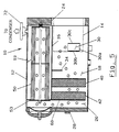
- Casing 12 is partitioned by divider plate 16 which, as best shown in Figure 5, does not extend the full length of casing 12.
- Divider plate 16 is welded to segmental baffle seal 60 to divide casing 12 into chambers 18 and 19. Referring now to Figures 3 and 4, it will be noted that divider plate 16, shown in phantom, is tilted a few degrees, eg.
- Cylindrical chamber 20 is located in the portion of casing 12 which is not partitioned by divider plate 16 and is defined in part by baffle seal 60.
- the cylinder/rotor assembly 14 extends through opening 24 of casing 12.
- the level of the oil in oil sump 26 is generally in the level range indicated by sightglasses 28 and 29 and the cylinder/rotor assembly 14 is normally partially submerged in the oil.
- the compressor discharge is in the form of a radial discharge at an angle of approximately 45° below horizontal and thus would normally impinge upon the surface of the oil sump 26 or could possibly be below the surface of the oil sump 26. This could cause entrainment of oil from the oil sump into the compressor discharge gas which already contains oil and exacerbate the oil removal problem.
- a discharge deflector 30 is provided which is shown in Figures 1, 3 and 5 with Figures 1 and 5 providing a view of discharge deflector 30 essentially as viewed from the compressor discharge.
- Discharge deflector 30, as best shown in Figure 3, provides an arcuate guide approximately 45-50° in extent.
- the arcuate surface 30 a together with side walls 30 b and c which conform to the shape of cylinder/rotor assembly 14, forms an arcuate trough surrounding cylinder/rotor assembly 14 at the discharge which has only an upwardly extending outlet when coacting with cylinder/rotor assembly 14. Since the discharge deflector 30 extends below the surface of the oil sump 26, oil tends to be present there at the same liquid level.
- the oil sump level and the amount and velocity of the discharge oil may be partially splashed out of the trough defined by the discharge deflector 30.
- the compressor discharge gas impinging upon the discharge deflector 30 may loose some entrained oil due to inertial forces upon being deflected but oil may also be entrained as a result of splashing.
- the discharge flow from the upwardly extending outlet defined by cylinder/rotor assembly 14 and discharge deflector 30 is in the form of a vertically upward flow on one side of the cylinder/rotor assembly 14 which impinges upon the bottom surface of tilted but generally horizontal divider plate 16. Impingement of the discharge flow with divider plate 16 produces a change in flow direction as indicated by the arrows in Figure 5 and due to inertial forces separates out a quantity of the entrained oil in large droplet from which deposits on the divider plate 16, the oil deposited on the divider plate 16 drips in droplets and/or, because of the tilt, flows by gravity to the interior wall of casing 12 defining chamber 18 and then flows downwardly to oil sump 26.
- the refrigerant gas which now contains only fine droplets or a mist of oil, passes serially through demister pads 40 and 42, respectively, which, as best shown in Figure 1, are partially immersed in the oil sump 26.
- the demister pads 40 and 42 remove oil by impingement and as the oil gathers in the fine wire mesh of the pads, it drains downwardly by gravity to maintain the oil reservoir defined by sump 26.
- Demister pads can extract as much as 99.9% of the oil still in circulation when it reaches the demister pads. The preliminary removal of the large oil droplets is therefore necessary to prevent overwhelming the demister pads and greatly increasing flow resistance.
- the demister pad 42 together with segmental baffle seal 60 serve to define and separate the chamber 20 from chambers 18 and 19.
- coalescer 50 As the now relatively oil-free refrigerant gas passes through demister pad 42 into chamber 20, it must make another 180° change in direction since, as best shown in Figure 4, the only exit from chamber 20 is via openings 51 and 52 in plate 53 which open into coalescer 50. Plate 53 of coalescer 50 is bolted to segmental baffle seal 60 with a gasket therebetween.
- Coalescer 50 is, in part, made of fiberglass and of a generally cylindrical shape and with no openings other than 51 and 52 which serve only as inlets. The refrigerant gas entering coalescer 50 via openings 51 and 52 must pass through the cylindrical fiberglass walls to reach chamber 19 thereby leaving any entrained oil trapped in the coalescing media of coalescer 50.
- coalesced oil gathers on the outside surface of coalescer 50 and drops downward, by gravity, as gravitational forces in the collected oil overcome viscous forces.
- This oil gathers on the top of tilted divider plate 16 and flows downwardly to the lowest portion of chamber 19 from which it is removed via oil return connection 70 and taken to a lower pressure section of the compressor. If desired, a depression may be formed in plate 16 adjacent connection 70 to further aid in collecting the oil by forming a well.
- the now nearly oil free refrigerant gas passes from coalescer 50 into chamber 19 and exits oil separator 10 via gas outlet connection 72 and is delivered to the condenser (not illustrated).
- oil collected and maintained in oil sump 26 is either re-injected into a lower pressure area of the compressor by pressure differential or passed through a pump (not illustrated) where its pressure is raised to be delivered back to the compressor.
- the oil is injected into the compressor to seal, lubricate and cool the mechanism.
- the tilt of divider plate 16 can be increased from the preferred 3° to change the discharge gas flow path and/or to control whether oil drips and/or flows from divider plate 16 and in what proportions.
Description
- The present invention relates generally to an oil separator for a horizontal screw compressor and to a method for removing oil from the discharge of the screw compressor.
- Screw compressors employed in refrigeration applications commonly use oil for sealing, lubricating and cooling. The oil is injected into the working chamber of the compressor and thus into the refrigerant gas being compressed. As a result, the compressor discharge ordinarily contains oil entrained in the compressed refrigerant gas. The presence of oil interferes with the heat exchange function of the refrigeration system and otherwise degrades the efficiency of the system. Generally, the amount of oil carried over is kept as low as possible in order to minimize the degrading of the heat transfer surfaces, to minimize the return of oil from remote locations in the system and to keep a sufficient oil supply in the oil sump for sealing, lubricating and cooling needs. The oil removal or separation ordinarily takes place at a convenient place between the compressor discharge and the condenser.
- In EP-A-0 038 018 there is described a method for removing oil from the discharge of a compressor and an oil separator for a horizontal screw compressor comprising a generally cylindrical member having an opening for receiving the rotor assembly of the screw compressor. Discharge deflector means direct the discharge from the compressor generally downwardly whereby the discharge is diverted at least 90° and is caused to impinge upon a surface to thereby deposit entrained oil thereon. The impinging compressor discharge flow is caused to be diverted approximately 180° and then passes serially through a divider plate means and through demister means located in the cylindrical member to be directed out of the separator in a nearly oil-free state.
- It is an object of this invention to provide a more efficient oil separation in a screw compressor. It is another object of this invention to provide an oil separator which drains most of the separated oil directly to the oil sump. These objects, and others as will become apparent hereinafter, are accomplished by the present invention.
- To achieve this, the oll separator of the invention is characterized by the features set forth in claim 1 and the invention provides a method for removing oil from the compressor discharge according to claim 7. Advantageous embodiments of the invention are claimed in the subclaims.
- According to the principles of the invention, there is provided a plurality of flow direction changes in combination with a discharge deflector, demisters and a coalescer to remove and collect oil entrained in the refrigerant gas. Except for oil removed in the coalescer, all of the separated oil drains directly into the oil sump. The refrigerant gas and entrained oil is subjected to at least two impingements with a resulting change in direction to inertially remove as much oil as possible prior to reaching the demisters where the amount of oll removal has a direct, temporary effect on the demisters and their flow resistances as the entrained oll impinges, collects and drains to the sump.
- Basically the discharge from a horizontal screw compressor is directed radially and in a generally downward direction where it impinges upon the surface of the oil and/or a discharge deflector. The discharge deflector is generally in the shape of an arcuate trough about 45°-50° in extent. The arcuate portion is spaced from the compressor discharge and the discharge deflector surrounds the compressor discharge. Impingement of the discharge flow with the surface of the oil in the trough and/or the discharge deflector produces a directional flow change with a portion of the oil collecting in the oil pool and/or on the trough surface due to inertial forces as the flow direction changes. The trough guides the flow upwardly along its inner surface so that it impinges upon the lower surface of the divider plate which is titled a few degrees from horizontal such that oil striking and collecting on the lower surface flows along the tilted surface and drains back to the sump by gravity. The discharge flow changes direction due to its impingement upon the lower surface and impinges upon and is diverted by a baffle plate extending downwardly from the divider plate which also collects oil impinging thereon due to inertia. The discharge flow then serially passes through two demister pads, impinges upon the end of the oil separator housing and is diverted upward. The flow then turns to enter the coalescer completing a 180° change of direction after passing through the demisters. The flow passes through the walls of the coalescer leaving any entrained oil trapped in the coalescing media of the element. The coalesced oil gathers on the outside diameter of the coalescer and drops onto the upper surface of the tilted divider plate and is withdrawn via the oil return connection and passes back to a lower pressure section of the compressor. The refrigerant gas, now nearly oil free, exits the separator and is delivered to the condenser of the refrigeration system.
- For a fuller understanding of the present invention, reference should now be made to the following detailed description thereof taken in conjunction with the accompanying drawings wherein:
- Figure 1 is partially cut away side view of the oil separator of the present invention;
- Figure 2 is a first end view of the Figure 1 device;
- Figure 3 is a second end view of the Figure 1 device;
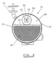
- Figure 4 is a sectional view taken along line 4-4 of Figure 1; and
- Figure 5 is a sectional view taken along line 5-5 of Figure 2.
- In the Figures, the
numeral 10 generally indicates the oil separator of the present invention. The external portion of theoil separator 10 is an essentially cylindrical shapedcasing 12 which is bolted or otherwise suitably secured to the casing of a screw compressor and receives therein a portion of the cylinder/rotor assembly 14 which is shown in phantom in Figures 1, 3 and 5.Casing 12 is partitioned bydivider plate 16 which, as best shown in Figure 5, does not extend the full length ofcasing 12.Divider plate 16 is welded tosegmental baffle seal 60 to dividecasing 12 intochambers divider plate 16, shown in phantom, is tilted a few degrees, eg. 1-6° with 3° preferred, from horizontal and that the portion of thecasing 12 belowdivider plate 16 defines a major segment of a circle which defineschamber 18 and a minor segment of a circle which defineschamber 19.Cylindrical chamber 20 is located in the portion ofcasing 12 which is not partitioned bydivider plate 16 and is defined in part bybaffle seal 60. - A horizontal screw compressor of which only the rotor and
cylinder assembly 14 is shown, and then only in phantom, is attached tocasing 12 by bolts (not illustrated) which are threaded into tappedbolt holes 22. The cylinder/rotor assembly 14 extends through opening 24 ofcasing 12. As best shown in Figure 1, the level of the oil inoil sump 26 is generally in the level range indicated bysightglasses rotor assembly 14 is normally partially submerged in the oil. The compressor discharge is in the form of a radial discharge at an angle of approximately 45° below horizontal and thus would normally impinge upon the surface of theoil sump 26 or could possibly be below the surface of theoil sump 26. This could cause entrainment of oil from the oil sump into the compressor discharge gas which already contains oil and exacerbate the oil removal problem. - As the first step of oil removal, a
discharge deflector 30 is provided which is shown in Figures 1, 3 and 5 with Figures 1 and 5 providing a view ofdischarge deflector 30 essentially as viewed from the compressor discharge.Discharge deflector 30, as best shown in Figure 3, provides an arcuate guide approximately 45-50° in extent. Thearcuate surface 30a together withside walls 30b and c, which conform to the shape of cylinder/rotor assembly 14, forms an arcuate trough surrounding cylinder/rotor assembly 14 at the discharge which has only an upwardly extending outlet when coacting with cylinder/rotor assembly 14. Since thedischarge deflector 30 extends below the surface of theoil sump 26, oil tends to be present there at the same liquid level. However, depending upon several factors such as the degree of sealing between thedischarge deflector 30 and the cylinder/rotor assembly 14, the oil sump level and the amount and velocity of the discharge, oil may be partially splashed out of the trough defined by thedischarge deflector 30. The compressor discharge gas impinging upon thedischarge deflector 30 may loose some entrained oil due to inertial forces upon being deflected but oil may also be entrained as a result of splashing. - With reference to Figures 3 and 5, the discharge flow from the upwardly extending outlet defined by cylinder/
rotor assembly 14 anddischarge deflector 30 is in the form of a vertically upward flow on one side of the cylinder/rotor assembly 14 which impinges upon the bottom surface of tilted but generallyhorizontal divider plate 16. Impingement of the discharge flow withdivider plate 16 produces a change in flow direction as indicated by the arrows in Figure 5 and due to inertial forces separates out a quantity of the entrained oil in large droplet from which deposits on thedivider plate 16, the oil deposited on thedivider plate 16 drips in droplets and/or, because of the tilt, flows by gravity to the interior wall ofcasing 12 definingchamber 18 and then flows downwardly tooil sump 26. - The discharge flow impinging upon the bottom of
divider plate 16 is diverted by approximately 180° and dispersed over a larger flow area and then must again turn through approximately 90° to flow pastbaffle plate 34 and each of these directional changes tends to produce removal of oil by the action of inertial forces which tend to propel the entrained oil in a straight path. - The refrigerant gas, which now contains only fine droplets or a mist of oil, passes serially through
demister pads oil sump 26. The demister pads 40 and 42 remove oil by impingement and as the oil gathers in the fine wire mesh of the pads, it drains downwardly by gravity to maintain the oil reservoir defined bysump 26. Demister pads can extract as much as 99.9% of the oil still in circulation when it reaches the demister pads. The preliminary removal of the large oil droplets is therefore necessary to prevent overwhelming the demister pads and greatly increasing flow resistance. Thedemister pad 42 together withsegmental baffle seal 60 serve to define and separate thechamber 20 fromchambers - As the now relatively oil-free refrigerant gas passes through
demister pad 42 intochamber 20, it must make another 180° change in direction since, as best shown in Figure 4, the only exit fromchamber 20 is viaopenings plate 53 which open intocoalescer 50.Plate 53 ofcoalescer 50 is bolted tosegmental baffle seal 60 with a gasket therebetween. Coalescer 50 is, in part, made of fiberglass and of a generally cylindrical shape and with no openings other than 51 and 52 which serve only as inlets. The refrigerantgas entering coalescer 50 viaopenings chamber 19 thereby leaving any entrained oil trapped in the coalescing media ofcoalescer 50. The coalesced oil gathers on the outside surface ofcoalescer 50 and drops downward, by gravity, as gravitational forces in the collected oil overcome viscous forces. This oil gathers on the top of tilteddivider plate 16 and flows downwardly to the lowest portion ofchamber 19 from which it is removed viaoil return connection 70 and taken to a lower pressure section of the compressor. If desired, a depression may be formed inplate 16adjacent connection 70 to further aid in collecting the oil by forming a well. The now nearly oil free refrigerant gas passes fromcoalescer 50 intochamber 19 and exitsoil separator 10 viagas outlet connection 72 and is delivered to the condenser (not illustrated). - The oil collected and maintained in
oil sump 26 is either re-injected into a lower pressure area of the compressor by pressure differential or passed through a pump (not illustrated) where its pressure is raised to be delivered back to the compressor. The oil is injected into the compressor to seal, lubricate and cool the mechanism. - Although a preferred embodiment of the present invention has been illustrated and described, other changes will occur to those skilled in the art. For example, the tilt of
divider plate 16 can be increased from the preferred 3° to change the discharge gas flow path and/or to control whether oil drips and/or flows fromdivider plate 16 and in what proportions.
Claims (9)
a generally cylindrical member (12) having a closed first end and having a second end having an opening (24) therein for receiving the rotor assembly (14) of a screw compressor;
baffle seal means (60) spaced from said closed first end and defining therewith a first chamber (20);
generally horizontal divider plate means (16) extending between said baffle seal means (60) and said second end so as to divide said generally cylindrical member (12) to thereby define second and third chambers (18,19) with said second chamber (18) being beneath and larger than said third chamber (19);
said opening (24) in said second end communicates with said second chamber (18) whereby said second chamber (18) is adapted to receive the rotor assembly (14);
discharge deflector means (30) in said second chamber (18) for directing compressor discharge upwardly so as to impinge upon said divider plate means (16) and deposit entrained oil thereon;
demister means (40,42) in said second chamber (18) and coacting with said baffle seal means (60) to separate said second chamber (18) from said first chamber (20) so that compressor discharge must pass from said second chamber (18) through said demister means (40,42) to reach said first chamber (20);
coalescer means (50) located in said third chamber (19) and in fluid communication with said first chamber (20) whereby compressor discharge passing from said demister means (40,42) is diverted approximately 180° in said first chamber (20) and then the entire compressor discharge enters said coalescer means (50) and passes therethrough into said third chamber (19) in a nearly oil-free state.
said method comprising the steps of:
providing baffle seal means (60) spaced from said closed first end and defining therewith a first chamber (20);
dividing said generally cylindrical member (12) by a generally horizontal divider plate means (16) extending between said baffle seal means (60) and said second end so as to thereby define second and third chambers (18,19) with said second chamber (18) being beneath and larger than said third chamber (19), said opening (24) in said second end communicating with said second chamber (18);
directing the compressor discharge as it leaves the compressor into contact with discharge deflector means (30) in said second chamber (18) whereby the compressor discharge is diverted at least 90°;
causing the diverted compressor discharge to impinge upon said divider plate means (16) to thereby deposit entrained oil from the compressor discharge thereon and to cause the impinging compressor discharge flow to be diverted approximately 180°;
passing all of the compressor discharge flow through demister means (40,42) in said second chamber (18) to reach said first chamber (20);
causing all of the flow passing through said demister means (40,42) to be diverted approximately 180° in said first chamber (20) and to flow into a coalescer means (50) located in said third chamber (19);
causing all of the flow entering the coalescer means (50) to pass therethrough into said third chamber (19) in a nearly oil-free state;
directing the resultant essentially oil-free compressor discharge to a refrigeration system.
Applications Claiming Priority (2)
| Application Number | Priority Date | Filing Date | Title |
|---|---|---|---|
| US07/162,837 US4788825A (en) | 1988-03-02 | 1988-03-02 | Oil separator |
| US162837 | 1988-03-02 |
Publications (3)
| Publication Number | Publication Date |
|---|---|
| EP0331607A2 EP0331607A2 (en) | 1989-09-06 |
| EP0331607A3 EP0331607A3 (en) | 1990-12-27 |
| EP0331607B1 true EP0331607B1 (en) | 1992-08-05 |
Family
ID=22587328
Family Applications (1)
| Application Number | Title | Priority Date | Filing Date |
|---|---|---|---|
| EP89630040A Expired - Lifetime EP0331607B1 (en) | 1988-03-02 | 1989-02-28 | Oil separator |
Country Status (4)
| Country | Link |
|---|---|
| US (1) | US4788825A (en) |
| EP (1) | EP0331607B1 (en) |
| JP (1) | JPH0762575B2 (en) |
| DE (1) | DE68902332T2 (en) |
Families Citing this family (17)
| Publication number | Priority date | Publication date | Assignee | Title |
|---|---|---|---|---|
| US5001908A (en) * | 1990-02-23 | 1991-03-26 | Thermo King Corporation | Oil separator for refrigeration apparatus |
| US5170640A (en) * | 1991-03-04 | 1992-12-15 | Carrier Corporation | Oil separator |
| US5214937A (en) * | 1991-10-28 | 1993-06-01 | Carrier Corporation | Integral oil separator and muffler |
| US5311750A (en) * | 1992-12-17 | 1994-05-17 | Stark John P | Oil collector unit |
| KR100542150B1 (en) * | 1998-11-14 | 2006-04-12 | 한라공조주식회사 | Oil separator |
| US6206653B1 (en) | 1998-12-03 | 2001-03-27 | American Standard Inc. | Internal oil filter element for refrigeration compressor |
| US6018962A (en) * | 1998-12-16 | 2000-02-01 | American Standard Inc. | Centrifugal compressor oil sump demister apparatus |
| US6422396B1 (en) | 1999-09-16 | 2002-07-23 | Kaydon Custom Filtration Corporation | Coalescer for hydrocarbons containing surfactant |
| IT1307526B1 (en) * | 1999-12-03 | 2001-11-06 | Frigomec Srl | PERFECTED TYPE OIL SEPARATOR. |
| US7648682B2 (en) * | 2004-07-08 | 2010-01-19 | Air Products And Chemicals, Inc. | Wick systems for complexed gas technology |
| US7396381B2 (en) * | 2004-07-08 | 2008-07-08 | Air Products And Chemicals, Inc. | Storage and delivery systems for gases held in liquid medium |
| US8337577B1 (en) * | 2010-11-24 | 2012-12-25 | Tri-Flo International, Inc. | Method for separation and containment of solids, liquids, and gases |
| CN102538325A (en) * | 2012-02-03 | 2012-07-04 | 中国科学院理化技术研究所 | Condensing gathering separator for separating lubricating oil from refrigerant |
| JP6782517B2 (en) * | 2017-08-21 | 2020-11-11 | 株式会社前川製作所 | Oil separator |
| US10527331B2 (en) * | 2017-10-03 | 2020-01-07 | Hill Phoenix, Inc. | Compact individual multistage universal hybrid oil separator |
| EP3693684A1 (en) * | 2019-02-05 | 2020-08-12 | Carrier Corporation | Separator and method for separating lubricant from lubricant-charged gaseous refrigerant |
| US11167237B2 (en) * | 2019-07-17 | 2021-11-09 | Dekker Vacuum Technologies, Inc. | Air/oil separator |
Family Cites Families (16)
| Publication number | Priority date | Publication date | Assignee | Title |
|---|---|---|---|---|
| US1415418A (en) * | 1920-09-10 | 1922-05-09 | Wilhelm Schmidding | Arrangement for purifying and rendering odorless the exhaust gases of internal-combustion engines and the like |
| US1793064A (en) * | 1924-10-06 | 1931-02-17 | William M Tippett | Liquid control |
| US2405625A (en) * | 1944-10-28 | 1946-08-13 | Louis C Whiton | Dust separator |
| US2910136A (en) * | 1956-07-20 | 1959-10-27 | Black Sivalls & Bryson Inc | Apparatus for separating fluids |
| US3070977A (en) * | 1961-03-31 | 1963-01-01 | Heat X Inc | Refrigeration system, including oil separator and muffler unit and oil return arrangement |
| US3283532A (en) * | 1965-09-23 | 1966-11-08 | Vilter Manufacturing Corp | Refrigerating apparatus with oil separating means |
| US3408828A (en) * | 1967-09-08 | 1968-11-05 | Dunham Bush Inc | Refrigeration system and system for separating oil from compressed gas |
| HU171252B (en) * | 1974-05-24 | 1977-12-28 | Diosgyoeri Gepgyar | Sound absorpted mechanical oil expeller particularly for refrigeration cycle |
| US4204846A (en) * | 1978-05-26 | 1980-05-27 | Donaldson Company, Inc. | Self-cleaning air filter |
| US4256474A (en) * | 1978-11-20 | 1981-03-17 | Finite Filter Company, Inc. | Filter housing and filter assemblies utilizing the same |
| US4350504A (en) * | 1980-01-28 | 1982-09-21 | Century 21 Pollution Control, Inc. | Air cleaning system |
| DE3014148C2 (en) * | 1980-04-12 | 1985-11-28 | M.A.N. Maschinenfabrik Augsburg-Nürnberg AG, 8000 München | Oil separator for compressors in heat pumps and chillers |
| DE3263965D1 (en) * | 1982-01-28 | 1985-07-11 | Chang Ying Chung | Separator for compressed air |
| DE3442626A1 (en) * | 1984-11-22 | 1986-05-22 | Rotorcomp Verdichter GmbH, 8000 München | FLUID SEPARATOR, ESPECIALLY GAS / LIQUID SEPARATOR |
| US4662190A (en) * | 1985-12-10 | 1987-05-05 | Tischer James C | Integral slide valve-oil separator apparatus in a screw compressor |
| US4708723A (en) * | 1986-06-30 | 1987-11-24 | Howeth David Franklin | Rotary broom sweeper hopper |
-
1988
- 1988-03-02 US US07/162,837 patent/US4788825A/en not_active Expired - Fee Related
-
1989
- 1989-02-28 DE DE8989630040T patent/DE68902332T2/en not_active Expired - Lifetime
- 1989-02-28 EP EP89630040A patent/EP0331607B1/en not_active Expired - Lifetime
- 1989-03-02 JP JP1050930A patent/JPH0762575B2/en not_active Expired - Lifetime
Also Published As
| Publication number | Publication date |
|---|---|
| EP0331607A3 (en) | 1990-12-27 |
| DE68902332D1 (en) | 1992-09-10 |
| EP0331607A2 (en) | 1989-09-06 |
| JPH01269887A (en) | 1989-10-27 |
| JPH0762575B2 (en) | 1995-07-05 |
| US4788825A (en) | 1988-12-06 |
| DE68902332T2 (en) | 1993-02-18 |
Similar Documents
| Publication | Publication Date | Title |
|---|---|---|
| EP0331607B1 (en) | Oil separator | |
| EP0540459B1 (en) | Integral oil separator and muffler | |
| US4545742A (en) | Vertical axis hermetic helical screw rotary compressor with discharge gas oil mist eliminator and dual transfer tube manifold for supplying liquid refrigerant and refrigerant vapor to the compression area | |
| US4906264A (en) | Oil separator for separating and collecting oil entrained in refrigerant | |
| US5404730A (en) | Helical oil separator | |
| US4622048A (en) | Liquid-gas separator | |
| EP0487959B1 (en) | Oil separator | |
| US5246357A (en) | Screw compressor with oil-gas separation means | |
| US4568256A (en) | Lubricant separation in a scroll compressor | |
| EP1936201B1 (en) | Compressor system with oil separator | |
| EP1922131B1 (en) | Coalescing filter element with drainage mechanism | |
| US5553460A (en) | Horizontal oil separator/reservoir | |
| US4477233A (en) | Vertical axis hermetic helical screw rotary compressor with discharge gas oil mist eliminator and dual transfer tube manifold for supplying liquid refrigerant and refrigerant vapor to the compression area | |
| KR20180008751A (en) | Oil-lubricated slide vane rotary vacuum pump | |
| US4441871A (en) | Rotary compressors with primary and secondary oil separation means | |
| US6640559B1 (en) | Vertical oil separator for a chiller system | |
| JP2986889B2 (en) | Vane type compressor | |
| US11167237B2 (en) | Air/oil separator | |
| EP0050638B1 (en) | Rotary compressors | |
| US4280799A (en) | Compressor with guide baffles and gas-permeable material separating means | |
| JPH0281972A (en) | Rotary compressor | |
| GB2342602A (en) | Primary gas/oil separator for a two-stage separation system | |
| SU792044A1 (en) | Oil separator | |
| CN113739459A (en) | Vertical oil separator and refrigerating system | |
| AU7150981A (en) | Rotary compressors |
Legal Events
| Date | Code | Title | Description |
|---|---|---|---|
| PUAI | Public reference made under article 153(3) epc to a published international application that has entered the european phase |
Free format text: ORIGINAL CODE: 0009012 |
|
| AK | Designated contracting states |
Kind code of ref document: A2 Designated state(s): DE FR GB IT |
|
| RAP1 | Party data changed (applicant data changed or rights of an application transferred) |
Owner name: FES INC. |
|
| PUAL | Search report despatched |
Free format text: ORIGINAL CODE: 0009013 |
|
| AK | Designated contracting states |
Kind code of ref document: A3 Designated state(s): DE FR GB IT |
|
| 17P | Request for examination filed |
Effective date: 19910206 |
|
| 17Q | First examination report despatched |
Effective date: 19910515 |
|
| GRAA | (expected) grant |
Free format text: ORIGINAL CODE: 0009210 |
|
| AK | Designated contracting states |
Kind code of ref document: B1 Designated state(s): DE FR GB IT |
|
| ET | Fr: translation filed | ||
| REF | Corresponds to: |
Ref document number: 68902332 Country of ref document: DE Date of ref document: 19920910 |
|
| ITF | It: translation for a ep patent filed |
Owner name: UFFICIO BREVETTI RICCAR |
|
| PGFP | Annual fee paid to national office [announced via postgrant information from national office to epo] |
Ref country code: FR Payment date: 19930114 Year of fee payment: 5 |
|
| PGFP | Annual fee paid to national office [announced via postgrant information from national office to epo] |
Ref country code: GB Payment date: 19930119 Year of fee payment: 5 |
|
| PGFP | Annual fee paid to national office [announced via postgrant information from national office to epo] |
Ref country code: DE Payment date: 19930125 Year of fee payment: 5 |
|
| PLBE | No opposition filed within time limit |
Free format text: ORIGINAL CODE: 0009261 |
|
| STAA | Information on the status of an ep patent application or granted ep patent |
Free format text: STATUS: NO OPPOSITION FILED WITHIN TIME LIMIT |
|
| 26N | No opposition filed | ||
| PG25 | Lapsed in a contracting state [announced via postgrant information from national office to epo] |
Ref country code: GB Effective date: 19940228 |
|
| GBPC | Gb: european patent ceased through non-payment of renewal fee |
Effective date: 19940228 |
|
| PG25 | Lapsed in a contracting state [announced via postgrant information from national office to epo] |
Ref country code: FR Effective date: 19941031 |
|
| PG25 | Lapsed in a contracting state [announced via postgrant information from national office to epo] |
Ref country code: DE Effective date: 19941101 |
|
| REG | Reference to a national code |
Ref country code: FR Ref legal event code: ST |
|
| PG25 | Lapsed in a contracting state [announced via postgrant information from national office to epo] |
Ref country code: IT Free format text: LAPSE BECAUSE OF NON-PAYMENT OF DUE FEES;WARNING: LAPSES OF ITALIAN PATENTS WITH EFFECTIVE DATE BEFORE 2007 MAY HAVE OCCURRED AT ANY TIME BEFORE 2007. THE CORRECT EFFECTIVE DATE MAY BE DIFFERENT FROM THE ONE RECORDED. Effective date: 20050228 |