EP0331570A2 - Motorradrahmen - Google Patents
Motorradrahmen Download PDFInfo
- Publication number
- EP0331570A2 EP0331570A2 EP89400544A EP89400544A EP0331570A2 EP 0331570 A2 EP0331570 A2 EP 0331570A2 EP 89400544 A EP89400544 A EP 89400544A EP 89400544 A EP89400544 A EP 89400544A EP 0331570 A2 EP0331570 A2 EP 0331570A2
- Authority
- EP
- European Patent Office
- Prior art keywords
- head pipe
- frame
- bearing support
- halves
- parts
- Prior art date
- Legal status (The legal status is an assumption and is not a legal conclusion. Google has not performed a legal analysis and makes no representation as to the accuracy of the status listed.)
- Granted
Links
- 238000003466 welding Methods 0.000 claims description 7
- 238000010276 construction Methods 0.000 description 11
- 230000004048 modification Effects 0.000 description 6
- 238000012986 modification Methods 0.000 description 6
- 238000004519 manufacturing process Methods 0.000 description 5
- 238000000926 separation method Methods 0.000 description 5
- 238000005266 casting Methods 0.000 description 4
- 229910001234 light alloy Inorganic materials 0.000 description 4
- 239000000463 material Substances 0.000 description 4
- 229910000838 Al alloy Inorganic materials 0.000 description 3
- 238000000034 method Methods 0.000 description 3
- 230000003247 decreasing effect Effects 0.000 description 2
- 230000002093 peripheral effect Effects 0.000 description 2
- 238000005520 cutting process Methods 0.000 description 1
- 230000003467 diminishing effect Effects 0.000 description 1
- 230000000694 effects Effects 0.000 description 1
- 238000003754 machining Methods 0.000 description 1
- 238000003825 pressing Methods 0.000 description 1
Images


Classifications
-
- B—PERFORMING OPERATIONS; TRANSPORTING
- B62—LAND VEHICLES FOR TRAVELLING OTHERWISE THAN ON RAILS
- B62K—CYCLES; CYCLE FRAMES; CYCLE STEERING DEVICES; RIDER-OPERATED TERMINAL CONTROLS SPECIALLY ADAPTED FOR CYCLES; CYCLE AXLE SUSPENSIONS; CYCLE SIDE-CARS, FORECARS, OR THE LIKE
- B62K19/00—Cycle frames
- B62K19/18—Joints between frame members
- B62K19/28—Means for strengthening joints
-
- B—PERFORMING OPERATIONS; TRANSPORTING
- B62—LAND VEHICLES FOR TRAVELLING OTHERWISE THAN ON RAILS
- B62K—CYCLES; CYCLE FRAMES; CYCLE STEERING DEVICES; RIDER-OPERATED TERMINAL CONTROLS SPECIALLY ADAPTED FOR CYCLES; CYCLE AXLE SUSPENSIONS; CYCLE SIDE-CARS, FORECARS, OR THE LIKE
- B62K19/00—Cycle frames
- B62K19/02—Cycle frames characterised by material or cross-section of frame members
- B62K19/04—Cycle frames characterised by material or cross-section of frame members the material being wholly or mainly metallic, e.g. of high elasticity
- B62K19/12—Cycle frames characterised by material or cross-section of frame members the material being wholly or mainly metallic, e.g. of high elasticity having cast members
-
- B—PERFORMING OPERATIONS; TRANSPORTING
- B62—LAND VEHICLES FOR TRAVELLING OTHERWISE THAN ON RAILS
- B62K—CYCLES; CYCLE FRAMES; CYCLE STEERING DEVICES; RIDER-OPERATED TERMINAL CONTROLS SPECIALLY ADAPTED FOR CYCLES; CYCLE AXLE SUSPENSIONS; CYCLE SIDE-CARS, FORECARS, OR THE LIKE
- B62K19/00—Cycle frames
- B62K19/18—Joints between frame members
- B62K19/24—Screwed joints
-
- B—PERFORMING OPERATIONS; TRANSPORTING
- B62—LAND VEHICLES FOR TRAVELLING OTHERWISE THAN ON RAILS
- B62K—CYCLES; CYCLE FRAMES; CYCLE STEERING DEVICES; RIDER-OPERATED TERMINAL CONTROLS SPECIALLY ADAPTED FOR CYCLES; CYCLE AXLE SUSPENSIONS; CYCLE SIDE-CARS, FORECARS, OR THE LIKE
- B62K19/00—Cycle frames
- B62K19/30—Frame parts shaped to receive other cycle parts or accessories
- B62K19/32—Steering heads
-
- B—PERFORMING OPERATIONS; TRANSPORTING
- B62—LAND VEHICLES FOR TRAVELLING OTHERWISE THAN ON RAILS
- B62K—CYCLES; CYCLE FRAMES; CYCLE STEERING DEVICES; RIDER-OPERATED TERMINAL CONTROLS SPECIALLY ADAPTED FOR CYCLES; CYCLE AXLE SUSPENSIONS; CYCLE SIDE-CARS, FORECARS, OR THE LIKE
- B62K21/00—Steering devices
- B62K21/06—Bearings specially adapted for steering heads
Definitions
- the present invention relates to a frame for motorcyles and, more particularly, to a frame that a head pipe and frame elements connected therewith are formed as a cast part split into two parts, right and left, in the direction of vehicle width, and said right and left split parts are assembled by combining into one body.
- a frame for motorcycles is obtainable by combining a split-type light alloy casting divided into two parts, right and left, for example a frame disclosed in Laid-Open Japanese Patent Application No. Sho 61-129383.
- the frame disclosed therein is of the constitution that a unitary cast part split into right and left parts is assembled by combining by a plurality of bolts in the head pipe portion, and bearings (commonly angular contact ball bearings) supporting a handlebar turning shaft are pressed into the upper and lower ends of the head pipe with the right and left parts butted.
- the prior-art frame for motorcycles therefore, has a drawback that the bearing area of the head pipe has to be finished with a high dimensional accuracy after assembling the halves, and therefore it is a hard work to carry out a high-accuracy cutting operation of the head pipe section forming a part of a large frame, resulting in a high cost of production. Furthermore, it is necessary to increase the tightness of bolts in order to combine the right and left halves such that there will not occur stress concentration in the bearing area centering at split surfaces. To realize this, however, the number of the bolts must be increased or the adoptionn of large-diameter bolts is required, resulting in increased vehicle weight.
- the present invention has been accomplished with the technical background described above, and therefore has an object to provide a frame easy to manufacture at a low cost wherein the head pipe and frame elements connected therewith are formed as a casting comprising two right and left parts split in the direction of vehicle width, and the frame is assembled by combining the right and left split parts into one body, requiring neither high dimensional accuracy control nor increasing the tightness of bolts for fastening the right and left split parts.
- the object of the present invention described above can be accomplished by fixedly mounting the handlebar turning shaft bearing support members at the upper and lower ends of the head pipe disposed astride a portion belonging to each of the right and left split parts so as to withstand, in the relationship of mounting, a separating force acting on the right and left split parts.
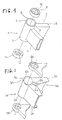
- This drawing is a perspective view showing a major portion of the frame including right and left halves 5, 1 and upper and lower bearing support members 9, 11 which constitute a vehicle frame of such a configuration that right and left main frame elements 4, 8 to be assembled en block extend from a head pipe to the rear of the vehicle body.
- the left half part 1 and the right half part 5 are monoblock cast parts of light alloy (e.g., aluminum alloy). From the head pipe half 2 of the left half part 1, the main frame element 4 of square tube extends; also from the head pipe half 6 of the right half part 5, the main frame element 8 of square tube extends.
- the right and left halves 1, 5 are joined by butt welding at the ends 3, 7 of the head pipe half parts 2,6, and also at a rear part not shown.
- annular bearing support members 9, 11 are joined by welding in proper alignment with the head pipe.
- the bearing support members 9, 11 have bearing mounting grooves 10, 12, in which the outer ring of the bearings supporting the handlebar turning shaft can be pressed.
- Adopting the frame of such construction insures tighter fastening of the right and left split frames and in addition does not require any improvement in its accuracy, thus attaining a frame of excellent processability at a low cost of manufacture.
- the annular bearing support members 9, 11 have been adopted, but there may be used a handle stopper restricting the handlebar turning angle, or a bearing support member having integrally formed support lugs for mounting a fairing to cover the front of vehicle. It is advantageous for the head pipe which is formed by assembling the halves to provide the annular bearing support members as integrally formed parts with the handlebar stopper to which a great deal of load is applied, and the fairing support lugs.
- Fig. 2 is a perspective view showing a major portion including right and left half parts 1A, 5A and upper and lower bearing support members 9A, 11A that constitute a vehicle frame of the configuration that a pair of right and left main frame elements 4A, 8A extend from the head pipe to the rear of the vehicle body.
- Either of the right and left half parts 1A, 5A is a monoblock casting produced of a light alloy (e.g., aluminum alloy).
- a light alloy e.g., aluminum alloy
- To the head pipe half 2A of the left half part 1A is connected the main frame element 4A of a channel material, while to the head pipe half 6A of the right half part 5A is connected the main frame element 8A of a channel material.
- the left half part 1A and the right half part 5A are joined by butt welding not only at the ends 3A, 7A of the head pipe halves 2A, 6A but at the ends 4a, 8a of the main frame elements 4A, 8A.
- the bearing support members 9A, 11A are triangular parts which cover not only the upper and lower ends of the head pipe but a part of the main frame elements 4A, 8A, their whole body being welded to the head pipe halves 2A, 6A.
- This construction has the advantage that the assembly-type head pipe halves and the front part of the main frame elements 4A, 8A connected thereto are more effectively increased in strength and rigidity than those of the embodiment previously stated.
- the bearing support members of this configuration may be installed only at either of the upper and lower ends of the head pipe, and the other may be merely an annular part.
- Fig. 3 shows only the upper end portion of the head pipe 13 assembled by the procedure shown in Figs. 1 and 2.
- the annular bearing support member 9B At this upper end portion of the head pipe 13 is welded the annular bearing support member 9B and a bearing 14 pressed in its bearing mounting groove 10B supports the handlebar turning shaft 15.
- This example of modification features a small-diameter lower half part of the bearing support member 9B, which is fitted (lightly pressed) in the head pipe 13, and a greater strength and rigidity of the jointed section of the bearing support member in relation to the head pipe as compared with the example shown in Fig. 1.
- Fig. 4 shows a projection 17 provided around the inside wall, near the upper end, of the head pipe 16 assembled by the method shown in Figs. 1 and 2.
- the bearing support member 9C welded to the upper end of the head pipe 16 and the outer ring 18 of a bearing just pressed in the upper end section of the head pipe 16 are in contact with this projection 17.
- This construction has the advantage that the outer ring 18 increases the strength and rigidity of the joint section of the head pipe 16 and the bearing support member 9C.
- Fig. 5 shows only the upper end section of the head pipe assembled by the method shown in Figs. 1 and 2.
- a small-diameter section 20 reduced in diameter in steps is formed.
- the annular bearing support member 9D is press-fitted (pressing of the small-diameter section 20 into the bearing support member 9D).
- the bearing support member 7D and the head pipe 10 may be welded as shown in Fig. 3.
- the handlebar turning shaft 15 is supported on the bearing 21 pressed in the bearing mounting groove 10D of the bearing support member 9D.
- a feature of this modification lies in that the head pipe 19 consisting of the right and left split parts is unitized firmly by the bearing support member 9D fitted on the small-diameter portion 20, and that because the great ridigity of the head pipe 19 can be maintained simply by combining the bearing support member 9D, the welding of the right and left halves of the head pipe 19 portion may be omitted, and also in the case of the frame disclosed in Laid-Open Japanese Patent Application No. Sho 61-129383 in which the tight and left split parts are assembled by bolts, the bolts in the head pipe section may be omitted.
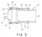
- Figs. 6 and 7 differ from those of the embodiments described above, and are of such a type that the right and left halves of the frame are assembled into one body by bolts.
- a left half part 22 and a right half part 28 are monoblock cast parts either produced of a light alloy (e.g., aluminum alloy).
- a head pipe half 23 of the left half part 22 is connected with a main frame element 26 of channel material, while a head pipe half 29 of the right half part 28 is connected to a main frame element 32 of channel material.
- the left half part 22 and the right half part 28 are butt-jointed at the ends 24, 30 of the head pipe halves 23, 29, at the ends 27, 33 of the main frame elements 26, 32 and at fairing support lugs 25, 31 projecting from the head pipe halves 23, 29, and fastened into one body by a plurality of tightening bolts 34.
- Bearing support members 35, 40 comprise annular sections 36, 41 having bearing mounting grooves 37, 42, bifurcated branches 38, 43, and lugs 39, 44, each being so shaped as to cover not only the upper and lower ends of the head pipe thus assembled but also a part of the main frame elements 26, 32, and fasened by a plurality of tightening bolts 45 to the head pipe halves 23, 29 (in Fig. 7, numeral 46 denotes the outer ring of a bearing).
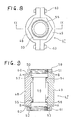
- a head pipe core tube as a handlebar turning shaft bearing support member is disposed inside the right and left head pipe halves cast.
- the head pipe halves 48, 49 constituting the head pipe 47 form a part of the right and left halves as casting illustrated in Figs. 1, 2 and 6, with the main frame elements integrally connected therewith not shown.
- the head pipe halves 48, 49 having a semi-circular transverse cross section, including the cylindrical head pipe core tube 56, are integrally connected by a plurality of tightening bolts and nuts 63 and nuts 59, 61 described later.
- the head pipe halves 48, 49 have projections at the upper and lower ends and on the inner peripheral surface, and the ring-like projections of the head pipe halves 48, 49 thus assembled are illustrated as an upper end projection 50, a lower end projection 52, an inner first projection 54, and an inner second projection 55.
- the head pipe core tube 56 has large-diameter portions 57, 58 formed at the upper and lower ends respectively, and the nuts 59, 61 are screwed onto the large-diameter portions 57, 58 having screw threads in its outer periphery.
- Inclined bearing surfaces 60, 62 formed in the inner periphery of the nuts 59, 61 come in contact with the inclined bearing surfaces 51, 53 of the upper end projection 50 and the lower end projection 52.
- the tightening force applied to these nuts works to fasten the head pipe core tube 56 to the head pipe haves 48, 49, and, at the same time, works to bring the head pipe halves 48, 49 into close contact with each other, thus firmly combining the head pipe halves 48, 49.
- the outside diameter of the large-diameter portions 57, 58 are nearly equal to the inside diameter of the cylindrical head pipe halves 48, 49 when fully tightened through the tightening bolts and nuts 63 and the nuts 59, 61. That is, the inner first projection 54 and the inner second projection 55 are projecting so as to nearly fit the step portions at the large-diameter portions 57, 58 and small-diameter portion of the head pipe core tube 56.
- This embodiment has the following features. As the nuts 59, 61 are tightened to the large-diameter portions 57, 58, a great tightening force for preventing the separation of the head pipe halves 48, 49 acts on the upper end projection 50 and the lower end projection 52, thereby maintaining considerable rigidity of the head pipe 47.
- the separation of the head pipe halves 48, 49 can effectively be prevented by the head pipe halves 49, 61, thereby decreasing the number of the tightening bolts and nuts 63 or the diameter of these tightening bolts and nuts 63 and consequently reducing vehicle weight.
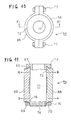
- FIGs. 10 and 11 show variations of the head pipe 47 shown in Figs. 8 and 9.
- Head pipe halves 65, 66 constituting a head pipe 64 have a semi-circular cross section and are assembled into one body, together with the cylindrical head pipe core tube 71, by the tightening bolts and nuts 77, a collar 72, and a nut 75.
- the head pipe halves 65, 66 have an upper end projection 67 and a lower end projection 69, the upper end projection 67 being disposed in an annular groove formed in the base portion of the collar 72 projecting from the upper end of the head pipe core tube 71.
- the inclined bearing surface 68 formed on the outer periphery of the upper end projection 67 is in contact with the inclined bearing surface 73 of the annular groove described above, and also the inclined bearing surface 76 of the nut 75 engaged with the threaded portion 74 of the head pipe core tube 71 is in contact with the inclined bearing surface 70 of the lower end projection 69.
- the axial force produced by tightening the nut 75 in engagement with the threaded portion74 of the head pipe core tube 71 acts on the lower end projection 69 and the upper end projection 67 in the relationship of contact between the inclined bearing surfaces 76 and 70 and between the inclined bearing surfaces 73 and 68, thereby working toward tightening the head pipe halves 65, 66 to firmly combine them.
- the collar 72 of the head pipe core tube 71 has the similar function as the nut 59.
- a great tightening force for preventing the separation of the head pipe halves 65, 66 acts on the upper end projection 67 and the lower end projection 69, thereby maintaining considerable rigidity of the head pipe 64. Therefore, even when a lateral tilting force indicated by the arrow A or B has been exerted from the head pipe core tube 71 which supports the handlebar turning shaft during riding, to the inner second projections 55, 66, the separation of the head pipe halves 65, 66 can effectively be prevented by the collar 72 and the nut 75. Consequently, it is possible to decrease the number and diameter of the tightening bolts and nuts 77, thereby reducing vehicle weight.
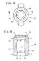
- Figs. 12 and 13 also are similar schematic drawings as Figs. 8 and 11.
- the head pipe halves 79, 80 of semi-circular cross section which constitute the head pipe 78 are combined, together with the cylindrical head pipe core tube 83 into one body by a plurality of tightening bolts and nuts 87.
- the head pipe halves 79, 80 have projections around the inner peripheral surface, that is, an inner first projection 81 and an inner second projection 82 either forming an annular projection when the head pipe halves 79, 80 are assembled.
- the upper and lower ends of the head pipe core tube 83 are larger in diameter than the middle portion.
- a collared nut 86 is installed on the screw formed on the outer periphery of the large-diameter portion 85.
- the collared nut 86 is seated on the upper ends of the head pipe halves 79, 80, and the axial force applied to the large-diameter portion 85 by the mounting of the collared nut 86 works as a force to press the head pipe halves 79, 80 in the direction of the axis in the relationship of contact between the collared nut 86 and the top ends of the head pipe halves 79, 80 and between the large-diameter portion 84 and the lower surface of the inner second projection 82.
- the large-diameter portion 85 is off from the inner first projection 81.
- the lateral tilting force changes into a pressure applied to the head pipe halves 79, 80 in the direction of the axis, thus diminishing loads exerted to the tightening bolts and nuts 87 used to combine the head pipe halves 79, 80.
- This is effective to prevent the separation of the head pipe halves 79, 80.
- the present invention is capable of insuring the reduction of loads exerted to the joint section of the head pipe halves by mounting the bearing support members. And the assembled head pipe and its vicinity are increased in strength and rigidity by the bearing support members and the relationship of this mounting.
- the number of bolts for combining the head pipe and its vicinity can be decreased, or the diameter of bolts can be made smaller, thereby reducing the weight of the vehicle frame.
Landscapes
- Engineering & Computer Science (AREA)
- Mechanical Engineering (AREA)
- Automatic Cycles, And Cycles In General (AREA)
- Motorcycle And Bicycle Frame (AREA)
Applications Claiming Priority (2)
| Application Number | Priority Date | Filing Date | Title |
|---|---|---|---|
| JP24495/88 | 1988-02-27 | ||
| JP2449588U JPH01112186U (de) | 1987-09-01 | 1988-02-27 |
Publications (3)
| Publication Number | Publication Date |
|---|---|
| EP0331570A2 true EP0331570A2 (de) | 1989-09-06 |
| EP0331570A3 EP0331570A3 (en) | 1990-07-04 |
| EP0331570B1 EP0331570B1 (de) | 1993-05-12 |
Family
ID=12139758
Family Applications (1)
| Application Number | Title | Priority Date | Filing Date |
|---|---|---|---|
| EP89400544A Expired - Lifetime EP0331570B1 (de) | 1988-02-27 | 1989-02-27 | Motorradrahmen |
Country Status (1)
| Country | Link |
|---|---|
| EP (1) | EP0331570B1 (de) |
Cited By (1)
| Publication number | Priority date | Publication date | Assignee | Title |
|---|---|---|---|---|
| GB2345676B (en) * | 1999-01-15 | 2002-09-18 | Satoshi Tange | Headset assembly for a bicycle |
Family Cites Families (4)
| Publication number | Priority date | Publication date | Assignee | Title |
|---|---|---|---|---|
| GB336045A (de) * | 1929-03-07 | 1930-10-09 | Zschopauer Motorenwerke J.S. Rasmussen, Aktien-Gesellschaft | |
| GB381334A (en) * | 1931-10-09 | 1932-10-06 | Arthur Edmund Mayo | Improvements in frames for cycles and motor-cycles |
| FR1323651A (fr) * | 1962-02-27 | 1963-04-12 | App Control Equip Moteurs | Perfectionnements apportés aux cadres de bicyclettes, notamment pour bicyclettes àmoteur auxiliaire |
| FR1367704A (fr) * | 1963-06-14 | 1964-07-24 | Lines Freres S A | Perfectionnements apportés à la construction des cadres de cycles d'enfants |
-
1989
- 1989-02-27 EP EP89400544A patent/EP0331570B1/de not_active Expired - Lifetime
Cited By (1)
| Publication number | Priority date | Publication date | Assignee | Title |
|---|---|---|---|---|
| GB2345676B (en) * | 1999-01-15 | 2002-09-18 | Satoshi Tange | Headset assembly for a bicycle |
Also Published As
| Publication number | Publication date |
|---|---|
| EP0331570B1 (de) | 1993-05-12 |
| EP0331570A3 (en) | 1990-07-04 |
Similar Documents
| Publication | Publication Date | Title |
|---|---|---|
| US5290052A (en) | Mechanically joined steering assembly | |
| US7841612B2 (en) | Bicycle fork and steering tube | |
| US6616156B1 (en) | Steering knuckle | |
| KR101115491B1 (ko) | 스티어링 너클 및 조정 보스 | |
| US4540193A (en) | Rear motorcycle fork | |
| US5626355A (en) | Telescoping-type front fork bicycle suspensions | |
| US5852954A (en) | Bicycle crank arm parts/assembly and assembly tools | |
| US6393939B1 (en) | Bicycle crank arm parts/assembly and assembly tools | |
| US4852678A (en) | Vehicle body frame for motorcycle | |
| EP1832448A1 (de) | Drehstabfederung | |
| EP0331570A2 (de) | Motorradrahmen | |
| JPS61291281A (ja) | 自動二輪車の車体フレ−ム構造体 | |
| EP0330557B1 (de) | Motorradrahmen | |
| US5275471A (en) | Composite vehicular wheel | |
| US8528927B2 (en) | Steering apparatus for a vehicle | |
| US20060288818A1 (en) | Attachment group of a pedal crank to the central axle of a bottom bracket of a bicycle transmission | |
| US4576058A (en) | Worm assembly | |
| JP2872989B1 (ja) | 車両の操向装置 | |
| EP1612133B1 (de) | Motorrad | |
| JPH0241300Y2 (de) | ||
| JPH0452425Y2 (de) | ||
| US20030146595A1 (en) | Bicycle headset construction | |
| JPH01168586A (ja) | フロントフォーク支持用アッパブラケットの締結構造 | |
| JPH068165Y2 (ja) | 鋳造ダイヤフラム | |
| JP3565633B2 (ja) | トンネル用セグメント |
Legal Events
| Date | Code | Title | Description |
|---|---|---|---|
| PUAI | Public reference made under article 153(3) epc to a published international application that has entered the european phase |
Free format text: ORIGINAL CODE: 0009012 |
|
| AK | Designated contracting states |
Kind code of ref document: A2 Designated state(s): FR IT |
|
| PUAL | Search report despatched |
Free format text: ORIGINAL CODE: 0009013 |
|
| AK | Designated contracting states |
Kind code of ref document: A3 Designated state(s): FR IT |
|
| 17P | Request for examination filed |
Effective date: 19900824 |
|
| 17Q | First examination report despatched |
Effective date: 19911206 |
|
| GRAA | (expected) grant |
Free format text: ORIGINAL CODE: 0009210 |
|
| AK | Designated contracting states |
Kind code of ref document: B1 Designated state(s): FR IT |
|
| ITF | It: translation for a ep patent filed | ||
| ET | Fr: translation filed | ||
| PGFP | Annual fee paid to national office [announced via postgrant information from national office to epo] |
Ref country code: FR Payment date: 19950224 Year of fee payment: 7 |
|
| PG25 | Lapsed in a contracting state [announced via postgrant information from national office to epo] |
Ref country code: FR Effective date: 19961031 |
|
| REG | Reference to a national code |
Ref country code: FR Ref legal event code: ST |
|
| PG25 | Lapsed in a contracting state [announced via postgrant information from national office to epo] |
Ref country code: IT Free format text: LAPSE BECAUSE OF NON-PAYMENT OF DUE FEES Effective date: 20050227 |
|
| PLBE | No opposition filed within time limit |
Free format text: ORIGINAL CODE: 0009261 |
|
| STAA | Information on the status of an ep patent application or granted ep patent |
Free format text: STATUS: NO OPPOSITION FILED WITHIN TIME LIMIT |