EP0331548B1 - Verfahren und Gerät zum Prüfen von Ultraschallwandlern - Google Patents
Verfahren und Gerät zum Prüfen von Ultraschallwandlern Download PDFInfo
- Publication number
- EP0331548B1 EP0331548B1 EP89400394A EP89400394A EP0331548B1 EP 0331548 B1 EP0331548 B1 EP 0331548B1 EP 89400394 A EP89400394 A EP 89400394A EP 89400394 A EP89400394 A EP 89400394A EP 0331548 B1 EP0331548 B1 EP 0331548B1
- Authority
- EP
- European Patent Office
- Prior art keywords
- detectors
- matrix
- image
- amplitude
- ultrasonic wave
- Prior art date
- Legal status (The legal status is an assumption and is not a legal conclusion. Google has not performed a legal analysis and makes no representation as to the accuracy of the status listed.)
- Expired - Lifetime
Links
Images



Classifications
-
- G—PHYSICS
- G01—MEASURING; TESTING
- G01H—MEASUREMENT OF MECHANICAL VIBRATIONS OR ULTRASONIC, SONIC OR INFRASONIC WAVES
- G01H3/00—Measuring characteristics of vibrations by using a detector in a fluid
- G01H3/005—Testing or calibrating of detectors covered by the subgroups of G01H3/00
-
- G—PHYSICS
- G01—MEASURING; TESTING
- G01H—MEASUREMENT OF MECHANICAL VIBRATIONS OR ULTRASONIC, SONIC OR INFRASONIC WAVES
- G01H3/00—Measuring characteristics of vibrations by using a detector in a fluid
- G01H3/10—Amplitude; Power
- G01H3/12—Amplitude; Power by electric means
- G01H3/125—Amplitude; Power by electric means for representing acoustic field distribution
Definitions
- the present invention relates to the control of ultrasonic translators.
- Ultrasonic translators are commonly used in the industry to examine the internal structure of materials in order to perform non-destructive testing of parts. An ultrasonic wave is emitted by the translator and the received echo is analyzed to highlight any of the part examined. The reliability of the results obtained is based in particular on the quality of the translators used. A periodic check of the good functioning of the translators is therefore necessary.
- the present invention aims to provide a method and a device for easy and rapid control of the integrity of an ultrasonic translator at its place of use without calling on highly qualified people and complicated and expensive devices.
- the visualization of ultrasonic fields describes such a method and such a device, where a single hydrophone element immersed in demineralized water is used to scan the ultrasonic field in two lateral directions (x, y) to provide a two-dimensional image of the spatial distribution of the ultrasonic wave.
- a defect in the controlled translator results in local relative variations in the ultrasonic field emitted.
- a localized defect in the active component of the translator corresponds a zone of the radiation field in which the amplitude of the ultrasonic wave (US) has a value different from that measured under the same conditions at the same point of the beam emitted by the translator in good condition.
- US ultrasonic wave
- the visualization of the spatial distribution, in the plane of the array of detectors, of the emitted wave therefore makes it possible, by comparison of two readings taken at different times, to quickly and easily check the translator.
- the control is performed on the translator in transmission mode, it also applies to the same translator used in reception mode.
- the spatial distribution of the ultrasonic wave emitted is displayed in the form of an image formed of image elements each corresponding to a detector and which occupy in the image positions similar to those of the corresponding detectors in the detector matrix.
- Each picture element has a variable characteristic as a function of the amplitude of the incident wave at the level of the corresponding detector. This variable characteristic is chosen to allow easy visualization of the distribution of the intensity values, for example the color, the gray level, the brightness ...
- each picture element comprises several light-emitting members of different colors, for example diodes, the selection of the light-emitting member the operation of which must be controlled being made as a function of the value of the amplitude of the incident wave received at the corresponding detector.
- the invention also aims to provide a control device for the implementation of the method defined above.
- This device when in use, is of course supplemented by an electric pulse generator to cause the emission of an ultrasonic field.
- This generator can advantageously be that usually used with the translator to be checked.
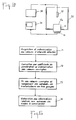
- the device illustrated in FIG. 1 is intended to control an ultrasonic translator 10 placed on a face 12a of a block 12 and receiving electrical pulses generated by a generator 14.
- a reception device 16 comprising a matrix of detectors 18 is fixed on the face 12b of the block 12 opposite and parallel to the face 12a.
- a signal processing circuit 40 is connected to the detectors 18 to receive from them electrical signals proportional to the amplitude of the ultrasonic wave coming from the translator 10 and having passed through the block 12.
- a display device 60 constituted by a matrix of electroluminiscent elements is controlled by the processing circuit 40 to form an image representative of the spatial distribution, at the level of the reception device, of the amplitude of the ultrasonic wave emitted by the translator 10.
- the piezoelectric sensitive element which will convert an electrical signal received into ultrasonic vibration (or vice versa) will be designated by ultrasonic transducer and by means of ultrasonic translator the assembly formed by one or more transducers, the means for mounting them. in a housing of the electrical connection means of the transducers to an external circuit.
- the ultrasonic translator 10 to be checked consists of any type of ultrasonic translator used in industry.
- the translator 10 is operated in emission mode and produces ultrasonic radiation in response to the electrical pulses (broadband) produced by the generator 14.
- the block 12 is intended to convey the ultrasonic radiation produced by the translator 10 to the receiving device 16.
- the block 12 is therefore made of a homogeneous material having good transparency to ultrasound, in particular a metal such as steel to fine grain, or even silica, and made with precision so as not to present defects liable to disturb the transmission of ultrasonic radiation in the block.
- the distance between the faces 12a and 12b is advantageously chosen to be large enough for the outlet face 12b to be located in the so-called "far field” zone, that is to say beyond the Fresnel zone, still “near field” which is quite disturbed, as we know.
- the useful signal will not be disturbed by echoes due to parasitic reflections of the US wave.
- the transition "near area" / "far area” is located approximately at a distance from the transducer given by the formula d2 / 4 ⁇ where d is the diameter of the transducer and ⁇ the wavelength of the ultrasound radiation emitted (d and ⁇ being taken with the same unit, generally in mm).
- This formula is usually used to define the location of the last maximum of the amplitude of the US wave on the axis of the transducer.
- the distance between the faces 12a and 12b must, of course, remain small enough for the received signal to be characteristic of the transducer to be checked and in particular to avoid too great a weakening of the radiation or the problems which could cause, for example, reflections on the lateral faces of the block 12 perpendicular to the faces 12a and 12b.
- the distance between the faces 12a and 12b is chosen between 2 cm and 10 cm, for example 4 cm.
- the dimensions of the block are chosen to be sufficient to cover those of the translator 10 to be checked and of the reception assembly 16, and to avoid parasitic reflections on the side walls as a result of the divergence of the emitted beam.
- the block 12 is produced in the form of a cylinder with a diameter equal to at least about twice that of the transducer contained in the translator 10.
- the translator 10 is applied against the face 12a with the interposition of an acoustic coupler such as petroleum jelly and other commercial couplers.
- an acoustic coupler such as petroleum jelly and other commercial couplers.
- the reception device consists of a set 16 of detectors 18 arranged in a matrix, for example 64 detectors arranged to form a square 8 ⁇ 8 matrix.
- Each detector consists of an ultrasonic transducer used for reception.
- the transducer matrix is produced, for example, according to a technology of the type described in French Patent No. 2,505,126.
- This connection is made by placing the piezoelectric chip at the bottom of a mold where a layer of a few mm of the damping mixture 22 is poured. The whole is then centrifuged to obtain a high concentration of tungsten powder in the immediate vicinity of the rear face of the tablet.
- Conductive sockets 20 (FIG.
- the individual transducers 18 are then formed, after hardening of the damper 22, by cutting the pellet by means of a diamond wire saw.
- the cutting is carried out according to a grid up to the part 24 of the damper not loaded with tungsten powder, therefore non-conductive.
- the cut performed, of pure epoxy resin, is poured into the grooves 26 between transducers 18 to electrically isolate them from each other.
- the reception device thus formed is fixed on the face 12b of the block 12 by bonding in thin film of the external face of the assembly 16 of the transducers 18 on the face 12b.
- the assembly is calibrated in order to determine the weighting coefficients to be applied to the signals supplied by the different translators in order to obtain signals of the same amplitude in response to an incident wave of the same level.
- the calibration can be carried out as follows ( Figure 3).
- the assembly formed by the receiving device 16 and the block 12 is placed at the bottom of a tank 30 with the face 12a facing upwards.
- the tank 30 is filled with liquid (water) and a reference ultrasonic translator 32 supplied by a generator 38 and working in immersion is suspended in the tank above said assembly.
- the signals produced by the translators of the reception device are selectively applied to an oscilloscope 34 which makes it possible to measure these signals.
- an oscilloscope 34 which makes it possible to measure these signals.
- the maximum of the amplitude of the signal received is sought by moving horizontally, in X, Y, the reference translator 32. When the maximum is reached, it is noted and the operation is repeated for each translator individual.
- the values noted will make it possible to calculate weighting coefficients associated with the various transducers 18, which make it possible to establish the uniformity of the sensitivities on the surface of the matrix of transducers.
- the weighting coefficients are memorized in order, during the subsequent use of the reception device, to correspondingly correct the signals supplied by the translators.
- the signals supplied by the transducers 18, in response to the emission of ultrasonic radiation by the translator to be checked 10, are applied to the processing circuit 40 to develop the control signals of the device display 60.
- the processing circuit 40 (FIG. 4) comprises a multiplexer 42 receiving in parallel the signals supplied by all the transducers of the reception device to transmit them sequentially to a peak detector 44.
- the peak detector 44 stores the amplitude in analog form peak-to-peak of the signal received from each transducer, which amplitude is representative of the amplitude of the ultrasonic wave incident on said transducer.
- An analog-to-digital converter 46 converts the detected peak-to-peak amplitudes into digital form in order to transmit this information to a computer 48.
- the computer 48 comprises, organized around a bus 50, a system card 52 comprising an arithmetic and logic unit and random access memories (RAM), a card 53 of read only memories (PROM) in which are stored in particular the programs necessary for the operation of the computer, and the input / output or interface circuits 54, 56a, 56b, 56c.
- a supply circuit (not shown) supplies the voltages necessary for the operation of the aforementioned circuits.
- the weighting coefficients for the signals produced by the transducers of the reception device used are recorded for example in a pluggable short memory (PROM) 58.
- the input / output circuits 54 form an interface between the computer 48 and a monitor 59, as well as between the computer 48 and a shaping circuit 41 receiving digital words representative of the addresses of transducers 18 in the matrix formed by these and developing corresponding control signals of the multiplexer 42.
- the circuits 56a, 56b, 56c form the interface between the computer 48 and the display device 60.
- the latter is produced in the form of a matrix display table comprising a number of boxes 62 equal to that of the individual transducers 18, each box 62 corresponding to a particular transducer which occupies in the transducer matrix the same location as the box in the display table.
- Each box 62 comprises several electroluminescent elements of different colors which are selectively actuated as a function of the amplitude of the ultrasonic wave incident on the corresponding transducer 18.
- the electroluminescent elements arranged in each box are three in number and formed by diodes 66a, 66b, 66c emitting in different colors such as green, yellow and red.
- the display device 60 is thus formed of three superimposed diode arrays which are controlled by information received from the computer through, respectively, the output circuits 56a, 56b, 56c and control circuits 64a, 64b, 64c.
- a control circuit for example the circuit 64a controlling the diodes 66a emitting in the green, is illustrated in FIG. 5.
- the diodes 66a are 64 in number, arranged in an array of 8 rows and 8 columns.
- the output circuit 56a provides eight eight-bit digital words (eight bytes) which each correspond to a particular line and which are stored in respective buffer registers RT1 to RT8.
- Each row of the matrix is supplied via the collector-emitter circuit of a particular line transistor (TL1 to TL8), and, likewise, each column of the matrix is supplied by a particular column transistor (TC1 to TC8).
- a multiplexer MUX receives a clock signal supplied by an oscillator OSC to activate sequentially its eight output terminals which are connected to the bases of the line transistors TL1 to TL8, respectively.
- the signals available on the output terminals of the multiplexer MUX also control the registers RT1 to RT8 associated with the lines.
- each buffer register RT1 to RT8 whose logic levels correspond to the bits of the bytes stored in the buffer register under the control of the multiplexer MUX, are respectively connected to the bases of the column transistors TC1 to TC8.
- the diode arrays 66b and 66c are similarly controlled from the digital words transmitted by the output circuits 56b and 56C.
- the choice of the light-emitting diode whose operation must be controlled is made as a function of the amplitude of the ultrasonic wave incident on the corresponding transducer.
- the digital signal obtained is assigned the weighting coefficient of the transducer to provide information amplitude which represents the amplitude of the ultrasonic wave in the area of the transducer and which is memorized in random access memory of the computer in combination with the address of the corresponding transducer.
- the different amplitude information stored after multiplexing the different transducers are sorted to form a certain number of groups, for example three groups: a first group in which the addresses of the transducers having supplied signals corresponding to amplitude information included are stored between the amplitude information of maximum levels and 3 dB below the maximum level (-3 dB to 0 dB), a second group in which the addresses of the transducers having supplied signals corresponding to amplitude information comprised between the level at -3 dB and the level at -6 dB relative to the maximum level, and a third group in which are stored the addresses of the transducers having supplied signals corresponding to amplitude information of level lower than -6 dB.
- groups for example three groups: a first group in which the addresses of the transducers having supplied signals corresponding to amplitude information included are stored between the amplitude information of maximum levels and 3 dB below the maximum level (-3 dB to 0 dB), a second group in which the addresses of the transducers having supplied signals
- the addresses of the transducers of the first group are converted into the form of digital words transmitted to the output circuit 56a to control, via the circuit 54a, the supply of the diodes 66a emitting in the green in the boxes 62 whose addresses correspond to those of the transducers first group.
- the addresses of the transducers of the second group are converted into the form of digital words transmitted to the output circuit 56b to control, via the circuit 64b, the supply of the diodes 66b emitting in yellow in the boxes 62 whose addresses correspond to those of the transducers of the second group
- the addresses of the transducers of the third group are converted into the form of digital words transmitted to the output circuit 56c to control, via the circuit 64c, the supply of the diodes 66c emitting in red in boxes 62 whose addresses correspond to those of the transducers of the third group.
- the device described above realizes a mapping of the radiation emitted by the translator to be checked.
- the display panel 60 immediately gives the image of the distribution, in the plane of the reception matrix, perpendicular to the general direction of transmission of the ultrasound, of the amplitude values of the wave.
- each image element can take one of three different colors.
- different colors it will be possible, for example, to choose different gray levels in a black and white image or else different brightness levels in a bright image.
- the invention is not limited by the size of the matrix considered in the example.
- a larger matrix for example of 16 ⁇ 16 transducers, may well be suitable.
- connection between the transducer matrix and the transmission block can be obtained by other means than bonding. It is only important to ensure permanent contact and pressure, preferably uniform, of all the elementary transducers on the surface 12a of the block 12.
- the invention is not limited either to the control of contact translators, but also applies to those intended to work with a coupling fluid and, in particular, those working in total immersion, as is the case of that shown in figure 3.
- the coupling between the face 12a of the transmission block and the translator to be checked can be ensured, either by a liquid or greasy seal, as provided in the example described in the case of a contact translator, or by the interposition of a column of water, or more generally of liquid, in the case of the control of an immersion translator.
Landscapes
- Physics & Mathematics (AREA)
- General Physics & Mathematics (AREA)
- Engineering & Computer Science (AREA)
- Acoustics & Sound (AREA)
- Radar, Positioning & Navigation (AREA)
- Remote Sensing (AREA)
- Investigating Or Analyzing Materials By The Use Of Ultrasonic Waves (AREA)
- Transducers For Ultrasonic Waves (AREA)
- Testing Or Calibration Of Command Recording Devices (AREA)
- Testing Electric Properties And Detecting Electric Faults (AREA)
Claims (9)
Priority Applications (1)
| Application Number | Priority Date | Filing Date | Title |
|---|---|---|---|
| AT89400394T ATE74204T1 (de) | 1988-02-29 | 1989-02-13 | Verfahren und geraet zum pruefen von ultraschallwandlern. |
Applications Claiming Priority (2)
| Application Number | Priority Date | Filing Date | Title |
|---|---|---|---|
| FR8802499A FR2627929B1 (fr) | 1988-02-29 | 1988-02-29 | Procede et dispositif de controle de traducteurs ultrasonores |
| FR8802499 | 1988-02-29 |
Publications (2)
| Publication Number | Publication Date |
|---|---|
| EP0331548A1 EP0331548A1 (de) | 1989-09-06 |
| EP0331548B1 true EP0331548B1 (de) | 1992-03-25 |
Family
ID=9363745
Family Applications (1)
| Application Number | Title | Priority Date | Filing Date |
|---|---|---|---|
| EP89400394A Expired - Lifetime EP0331548B1 (de) | 1988-02-29 | 1989-02-13 | Verfahren und Gerät zum Prüfen von Ultraschallwandlern |
Country Status (5)
| Country | Link |
|---|---|
| EP (1) | EP0331548B1 (de) |
| JP (1) | JPH0210167A (de) |
| AT (1) | ATE74204T1 (de) |
| DE (1) | DE68901051D1 (de) |
| FR (1) | FR2627929B1 (de) |
Families Citing this family (4)
| Publication number | Priority date | Publication date | Assignee | Title |
|---|---|---|---|---|
| DE3918810A1 (de) * | 1989-06-09 | 1990-12-13 | Bock Orthopaed Ind | Gelenkloser prothesenfuss |
| GB8924393D0 (en) * | 1989-10-30 | 1989-12-20 | Marconi Co Ltd | Transducer testing |
| DE3942588A1 (de) * | 1989-12-22 | 1991-06-27 | Krupp Atlas Elektronik Gmbh | Verfahren und vorrichtung zum ausgleichen von empfindlichkeitsstreuungen |
| US5890776A (en) * | 1996-04-26 | 1999-04-06 | Denso Corporation | Braking apparatus for automotive vehicles |
Family Cites Families (3)
| Publication number | Priority date | Publication date | Assignee | Title |
|---|---|---|---|---|
| US2957340A (en) * | 1956-03-15 | 1960-10-25 | Gen Electric | Ultrasonic image detector |
| GB1545505A (en) * | 1975-09-16 | 1979-05-10 | Ca Minister Nat Defence | Excitation and spectral calibration of acoustic emission systems |
| US4773140A (en) * | 1983-10-31 | 1988-09-27 | Advanced Technology Laboratories, Inc. | Phased array transducer construction |
-
1988
- 1988-02-29 FR FR8802499A patent/FR2627929B1/fr not_active Expired - Lifetime
-
1989
- 1989-02-13 DE DE8989400394T patent/DE68901051D1/de not_active Expired - Lifetime
- 1989-02-13 EP EP89400394A patent/EP0331548B1/de not_active Expired - Lifetime
- 1989-02-13 AT AT89400394T patent/ATE74204T1/de not_active IP Right Cessation
- 1989-02-28 JP JP1048381A patent/JPH0210167A/ja active Pending
Also Published As
| Publication number | Publication date |
|---|---|
| EP0331548A1 (de) | 1989-09-06 |
| JPH0210167A (ja) | 1990-01-12 |
| FR2627929A1 (fr) | 1989-09-01 |
| ATE74204T1 (de) | 1992-04-15 |
| FR2627929B1 (fr) | 1991-05-24 |
| DE68901051D1 (de) | 1992-04-30 |
Similar Documents
| Publication | Publication Date | Title |
|---|---|---|
| EP0335759B1 (de) | Ultraschallwindmesser | |
| EP0190805B1 (de) | Gerät zur Untersuchung von Medien mittels Ultraschallechographie | |
| FR2986145A1 (fr) | Procede et systeme pour surveiller une matrice de transducteurs dans un systeme d'echographie | |
| FR2844178A1 (fr) | Dispositif et procede pour la mesure de l'elasticite d'un organe humain ou animal et l'etablissement d'une representation a deux ou trois dimensions de cette elasticite | |
| EP0904535A1 (de) | Verfahren und vorrichtung zur erfassung und lokalisierung einer reflektierenden schallquelle | |
| EP0077585B1 (de) | Vorrichtung zur Untersuchung von Medien mittels Ultraschallechographie | |
| FR2872583A1 (fr) | Transducteur ultrasonore avec capteurs supplementaires | |
| CA2494828A1 (fr) | Dispositif et procede pour la mesure de l'elasticite d'un organe humain ou animal | |
| FR2589247A1 (fr) | Appareil d'exploration de milieux par echographie ultrasonore comprenant un reseau d'elements transducteurs piezoelectiques | |
| EP1531734A1 (de) | Nichtinvasives verfahren zur erzeugung eines vorbestimmten feldes akustischer wellen in einer von einer knochenbarriere verborgenen im wesentlichen homogenen umgebung, abbildungsverfahren und vorrichtung zur durchführung dieses verfahrens | |
| CA2082241A1 (fr) | Procede et dispositif de controle interne de pieces par ultrasons | |
| EP0342757A2 (de) | Ultraschall-Echographiegerät mit steuerbarer Phasenkohärenz | |
| CA2234465C (fr) | Procede et dispositif pour le traitement de signaux representatifs d'ondes reflechies, transmises ou refractees par une structure volumique en vue d'effectuer une exploration et une analyse de cette structure | |
| EP0543445A1 (de) | Untersuchungsgerät von Medien mittels Ultraschall-Echographie | |
| CA2933351A1 (fr) | Procede de traitement de signaux issus d'une acquisition par sondage ultrasonore, programme d'ordinateur et dispositif de sondage a ultrasons correspondants | |
| FR3101951A1 (fr) | Dispositif de contrôle ultrasonore et procédé de contrôle ultrasonore | |
| US4618934A (en) | Ultrasonic microscope apparatus | |
| EP0164808A1 (de) | Gerät zur Untersuchung von Medien mittels Ultraschallechographie | |
| EP0331548A1 (de) | Verfahren und Gerät zum Prüfen von Ultraschallwandlern | |
| WO2024074252A1 (fr) | Procede d'imagerie ultrasonore par transformee de fourier multidimensionnelle a l'aide de deux transducteurs multielements distincts | |
| US6740035B2 (en) | Ultrasonic receiving apparatus and ultrasonic diagnosing apparatus using the same | |
| EP0825453B1 (de) | Verfahren und Anordnung zur Bearbeitung von Signalen, welche durch ein Volumenstruktur reflektierte oder übertragene Wellen darstellen, um eine Forschung und Analyse der Struktur auszuführen | |
| EP2825876B1 (de) | Ultraschall-array-sonde und verfahren zum herstellen einer solchen sonde, steuerungsverfahren einer solchen sonde und entsprechendes computerprogramm | |
| FR2615960A1 (fr) | Dispositif de localisation d'un rayonnement nucleaire, et dispositif de formation d'image de rayonnement incluant un tel dispositif de localisation | |
| FR3065078B1 (fr) | Procede et dispositif de sondage ultrasonore par focalisation adaptative au moyen d'un objet solide reverberant |
Legal Events
| Date | Code | Title | Description |
|---|---|---|---|
| PUAI | Public reference made under article 153(3) epc to a published international application that has entered the european phase |
Free format text: ORIGINAL CODE: 0009012 |
|
| AK | Designated contracting states |
Kind code of ref document: A1 Designated state(s): AT BE CH DE ES GB GR IT LI LU NL SE |
|
| 17P | Request for examination filed |
Effective date: 19890923 |
|
| 17Q | First examination report despatched |
Effective date: 19910221 |
|
| GRAA | (expected) grant |
Free format text: ORIGINAL CODE: 0009210 |
|
| AK | Designated contracting states |
Kind code of ref document: B1 Designated state(s): AT BE CH DE ES GB GR IT LI LU NL SE |
|
| PG25 | Lapsed in a contracting state [announced via postgrant information from national office to epo] |
Ref country code: IT Free format text: LAPSE BECAUSE OF FAILURE TO SUBMIT A TRANSLATION OF THE DESCRIPTION OR TO PAY THE FEE WITHIN THE PRE;WARNING: LAPSES OF ITALIAN PATENTS WITH EFFECTIVE DATE BEFORE 2007 MAY HAVE OCCURRED AT ANY TIME BEFORE 2007. THE CORRECT EFFECTIVE DATE MAY BE DIFFERENT FROM THE ONE RECORDED.SCRIBED TIME-LIMIT Effective date: 19920325 Ref country code: NL Effective date: 19920325 Ref country code: SE Effective date: 19920325 Ref country code: ES Free format text: THE PATENT HAS BEEN ANNULLED BY A DECISION OF A NATIONAL AUTHORITY Effective date: 19920325 Ref country code: GB Effective date: 19920325 Ref country code: AT Effective date: 19920325 Ref country code: GR Free format text: LAPSE BECAUSE OF FAILURE TO SUBMIT A TRANSLATION OF THE DESCRIPTION OR TO PAY THE FEE WITHIN THE PRESCRIBED TIME-LIMIT Effective date: 19920325 |
|
| REF | Corresponds to: |
Ref document number: 74204 Country of ref document: AT Date of ref document: 19920415 Kind code of ref document: T |
|
| REF | Corresponds to: |
Ref document number: 68901051 Country of ref document: DE Date of ref document: 19920430 |
|
| NLV1 | Nl: lapsed or annulled due to failure to fulfill the requirements of art. 29p and 29m of the patents act | ||
| GBV | Gb: ep patent (uk) treated as always having been void in accordance with gb section 77(7)/1977 [no translation filed] | ||
| PLBE | No opposition filed within time limit |
Free format text: ORIGINAL CODE: 0009261 |
|
| STAA | Information on the status of an ep patent application or granted ep patent |
Free format text: STATUS: NO OPPOSITION FILED WITHIN TIME LIMIT |
|
| PG25 | Lapsed in a contracting state [announced via postgrant information from national office to epo] |
Ref country code: BE Effective date: 19930228 Ref country code: CH Effective date: 19930228 Ref country code: LI Effective date: 19930228 Ref country code: LU Free format text: LAPSE BECAUSE OF NON-PAYMENT OF DUE FEES Effective date: 19930228 |
|
| 26N | No opposition filed | ||
| BERE | Be: lapsed |
Owner name: INSTITUT DE RECHERCHES DE LA SIDERURGIE FRANCAISE Effective date: 19930228 Owner name: COMMUNAUTE EUROPEENNE DE L'ENERGIE ATOMIQUE EURAT Effective date: 19930228 |
|
| REG | Reference to a national code |
Ref country code: CH Ref legal event code: PL |
|
| PG25 | Lapsed in a contracting state [announced via postgrant information from national office to epo] |
Ref country code: DE Effective date: 19931103 |