EP0331473B1 - Poultry feed conveyor - Google Patents
Poultry feed conveyor Download PDFInfo
- Publication number
- EP0331473B1 EP0331473B1 EP89302054A EP89302054A EP0331473B1 EP 0331473 B1 EP0331473 B1 EP 0331473B1 EP 89302054 A EP89302054 A EP 89302054A EP 89302054 A EP89302054 A EP 89302054A EP 0331473 B1 EP0331473 B1 EP 0331473B1
- Authority
- EP
- European Patent Office
- Prior art keywords
- trough
- chain
- cross
- link
- links
- Prior art date
- Legal status (The legal status is an assumption and is not a legal conclusion. Google has not performed a legal analysis and makes no representation as to the accuracy of the status listed.)
- Expired - Lifetime
Links
Images

Classifications
-
- B—PERFORMING OPERATIONS; TRANSPORTING
- B65—CONVEYING; PACKING; STORING; HANDLING THIN OR FILAMENTARY MATERIAL
- B65G—TRANSPORT OR STORAGE DEVICES, e.g. CONVEYORS FOR LOADING OR TIPPING, SHOP CONVEYOR SYSTEMS OR PNEUMATIC TUBE CONVEYORS
- B65G19/00—Conveyors comprising an impeller or a series of impellers carried by an endless traction element and arranged to move articles or materials over a supporting surface or underlying material, e.g. endless scraper conveyors
- B65G19/14—Conveyors comprising an impeller or a series of impellers carried by an endless traction element and arranged to move articles or materials over a supporting surface or underlying material, e.g. endless scraper conveyors for moving bulk material in closed conduits, e.g. tubes
-
- A—HUMAN NECESSITIES
- A01—AGRICULTURE; FORESTRY; ANIMAL HUSBANDRY; HUNTING; TRAPPING; FISHING
- A01K—ANIMAL HUSBANDRY; AVICULTURE; APICULTURE; PISCICULTURE; FISHING; REARING OR BREEDING ANIMALS, NOT OTHERWISE PROVIDED FOR; NEW BREEDS OF ANIMALS
- A01K39/00—Feeding or drinking appliances for poultry or other birds
- A01K39/01—Feeding devices
-
- A—HUMAN NECESSITIES
- A01—AGRICULTURE; FORESTRY; ANIMAL HUSBANDRY; HUNTING; TRAPPING; FISHING
- A01K—ANIMAL HUSBANDRY; AVICULTURE; APICULTURE; PISCICULTURE; FISHING; REARING OR BREEDING ANIMALS, NOT OTHERWISE PROVIDED FOR; NEW BREEDS OF ANIMALS
- A01K5/00—Feeding devices for stock or game ; Feeding wagons; Feeding stacks
- A01K5/02—Automatic devices
- A01K5/0208—Automatic devices with conveyor belts or the like
Definitions
- This invention is concerned with a poultry feeding system
- a poultry feeding system comprising a storage hopper for feed, a flat-bottomed trough extending from the hopper along a continuous path, and an endless drag chain arranged to run along the bottom of the trough to move feed released from the hopper along the trough, the chain comprising links which each comprise a longitudinally-extending body traversed by a cross-piece which extends between the side walls of the trough to push the feed along the trough.
- Such equipment is suitable for use in moving feed along open troughs in intensive poultry houses, the feed so being brought to the birds in a controlled manner from a storage hopper.
- Various types of equipment used for this purpose include drag chains, metal centreless spirals, travelling hoppers and cable and disc conveyors.
- the present invention relates to equipment of that first kind, in which a travelling drag chain slides along the trough and so hauls the feed material along.
- the chain is endless, and its flexibility permits it to follow a suitable trough path from the hopper, through the poultry house and back to the hopper for recharging.
- Known drag chains of this kind comprise metal chain links which hook on to one another to form the endless chain.
- the links of such a drag chain are each formed to present a form of barrier across the trough, the barriers of the chain so serving to push the feed along the trough.
- each chain link comprising a longitudinally-extending body traversed by a cross-piece extending between side walls of the trough, the bodies and cross-pieces of the chain so forming a grid.
- a problem which arises with such known conveyors is wastage of feed through scooping and flicking of the feed by the birds.
- One known way of reducing that problem is to put a grid over the feeding trough, to limit the birds' movements in reaching the feed.
- the invention is characterised in that the cross-pieces present similar upstanding feed-engaging surfaces on each of opposite sides, at least the lower portions of which are raked from the lowermost edges of the cross-piece to provide a scraping action in sliding in either direction along the trough, upstanding bodies and cross-pieces of the chain forming a grid which compartmentalises the trough to inhibit flicking of feed from the trough by the poultry.
- each link is a unitary moulding of a plastics material and comprises coupling formations arranged for pivotal coupling of the link to the adjacent links in the chain.
- the coupling formations may be apertured to enable coupling pins to be introduced vertically through them.
- the formation at one end of the link comprises an eye and the formation at the other end of the link comprises a vertically-spaced pair of eyes, whereby the single eye at said one end of a link in a chain can be introduced between the pair of eyes at said other end of an adjacent link for coupling by means of a pin inserted vertically through the three aligned eyes.
- a feeding trough 10 In apparatus for conveying a powdery particulate feed material from a storage hopper to the birds in an intensive poultry house, a feeding trough 10 extends along a required path through the house.
- the trough extends continuously from, and back to, the storage hopper.
- An endless drag chain 12 lies in the bottom of the trough 10, on a flat bottom surface 14 between upstanding side walls 16 and 18 of the trough.
- a freely rotatable guide wheel 20 serves to guide the chain through the corner.
- the chain is made up of moulded plastics links 22 which are pivotally coupled together, end to end, by means of hardened steel pins 24.
- Each link of which one is shown in detail in Figures 2 and 3, is a unitary moulding of an acetal plastics resin.
- the link is of cruciform shape as seen in plan, comprising a longitudinally-extending body 26 crossed centrally, and perpendicularly, by a cross-piece 28.
- the body 26 comprises a middle portion which is in the general form of an upstanding web 30 which at each end is thickened (widthwise of the link, as seen in Figure 2) to merge with first and second coupling formations 32 and 34.
- the first coupling formation 32 forms co-axially arranged upper and lower eyes 36 and 38 which have aligned apertures 40 and 42, respectively, through them.
- the two eyes 36 and 38 are vertically spaced apart to form a slot 44 between them.
- the second coupling formation 34 forms a single eye 46 which is of similar thickness to the slot 44 (but not greater) and is at the same height as the slot above a flat cruciform bottom surface 48 of the link.
- An aperture 50 similar to the aligned apertures 40 and 42 in the first coupling formation, extends through the eye 46 of the second coupling formation, the axes of the three apertures 40,42 and 50 being perpendicular to the flat bottom surface 48 of the link.
- the cross-piece 28 of the link which extends equally to the two sides of the body 26, comprises a central portion 52 and two end portions 54 and 56.
- the length of the central portion is approximately half the length of the cross-piece as a whole.
- the central portion 56 forms a drive shoulder presenting a semi-cylindrical convex uppermost surface 58, which in the axial direction extends longitudinally of the cross-piece, and which arcuately extends between first and second side faces 60 and 62 which are perpendicular to the bottom surface 48 of the link.
- the surface 58 projects above a top surface 64 of the body 26.
- the two end portions 54 and 56 of the cross-piece are identical. Each comprises an upwardly-tapering lower portion 66 and a parallel-sided upper portion 68.
- the lower portion 66 comprises convergent first and second side faces 70 and 72; at the bottom surface 48, the lower portion is of the same width (i.e. measured lengthwise of the body 26) as the central portion 52 but the side faces 70 and 72 slope inwards, being equally but oppositely inclined to parallel planes perpendicular to the bottom surface 48.
- the upper portion 68 comprises first and second side faces 74 and 76 which are in parallel with those planes, as seen in the drawings.
- the form of the links serves to create a grid which compartmentalises the trough space to inhibit flicking of the feed by the poultry, so reducing wastage of the feed.
- the single eye 46 of each link is inserted into the slot 44 of a next link and a coupling pin 24 is inserted through the aligned apertures 40,42 and 50 to secure the links together pivotally.
- the bottom surfaces 48 of the links lie flat on the bottom surface 14 of the trough 10, the spacing between the side walls 16 and 18 of the trough being similar (but not less than) the length of the chain cross-pieces 28.
- the chain is so arranged to slide along the trough, pushing feed material along from the point of supply at the storage hopper by means, principally, of the cross-pieces 28.
- the chain can be driven with equal effect in either direction, the first and second side faces 60, 70, 74 and 62, 72, 76, respectively, being arranged in the same way.
- the raked-back side faces 70 and 72, extending from lowermost edges of the cross-piece, are arranged to give a scraping action which resists any tendency for the links to ride over the feed in the trough.
- the chain can be driven by means of an overhead double sprocket wheel (not shown) engaging the half-round drive shoulders formed by the central portions 52 of the links, the pairs of sprocket teeth straddling the body web 30 of each link in turn to engage the drive shoulder to each side of the web.
- the guide wheel 20, such as can be provided at each corner of the trough path, provides a lower cylindrical surface 78 to be engaged by end faces 80 of the link cross-pieces, and an upper cylindrical surface 82 of greater diameter to be engaged by end faces 84 of the drive shoulders, as can be seen in Figure 1.
Landscapes
- Life Sciences & Earth Sciences (AREA)
- Environmental Sciences (AREA)
- Birds (AREA)
- Animal Husbandry (AREA)
- Biodiversity & Conservation Biology (AREA)
- Engineering & Computer Science (AREA)
- Mechanical Engineering (AREA)
- Feeding And Watering For Cattle Raising And Animal Husbandry (AREA)
- Chain Conveyers (AREA)
- Pusher Or Impeller Conveyors (AREA)
- Processing Of Meat And Fish (AREA)
Description
- This invention is concerned with a poultry feeding system comprising a storage hopper for feed, a flat-bottomed trough extending from the hopper along a continuous path, and an endless drag chain arranged to run along the bottom of the trough to move feed released from the hopper along the trough, the chain comprising links which each comprise a longitudinally-extending body traversed by a cross-piece which extends between the side walls of the trough to push the feed along the trough.
- Such equipment is suitable for use in moving feed along open troughs in intensive poultry houses, the feed so being brought to the birds in a controlled manner from a storage hopper.
- Various types of equipment used for this purpose include drag chains, metal centreless spirals, travelling hoppers and cable and disc conveyors. The present invention relates to equipment of that first kind, in which a travelling drag chain slides along the trough and so hauls the feed material along. The chain is endless, and its flexibility permits it to follow a suitable trough path from the hopper, through the poultry house and back to the hopper for recharging. Known drag chains of this kind comprise metal chain links which hook on to one another to form the endless chain. The links of such a drag chain are each formed to present a form of barrier across the trough, the barriers of the chain so serving to push the feed along the trough.
- An example of a poultry feed conveyor incorporating such a drag chain is shown in FR-E-77402, each chain link comprising a longitudinally-extending body traversed by a cross-piece extending between side walls of the trough, the bodies and cross-pieces of the chain so forming a grid.
- A problem which arises with such known conveyors is wastage of feed through scooping and flicking of the feed by the birds. One known way of reducing that problem is to put a grid over the feeding trough, to limit the birds' movements in reaching the feed.
- The invention is characterised in that the cross-pieces present similar upstanding feed-engaging surfaces on each of opposite sides, at least the lower portions of which are raked from the lowermost edges of the cross-piece to provide a scraping action in sliding in either direction along the trough, upstanding bodies and cross-pieces of the chain forming a grid which compartmentalises the trough to inhibit flicking of feed from the trough by the poultry.
- Preferred features of the invention are set out in the dependent claims. Preferably, each link is a unitary moulding of a plastics material and comprises coupling formations arranged for pivotal coupling of the link to the adjacent links in the chain. The coupling formations may be apertured to enable coupling pins to be introduced vertically through them. In a preferred arrangement, the formation at one end of the link comprises an eye and the formation at the other end of the link comprises a vertically-spaced pair of eyes, whereby the single eye at said one end of a link in a chain can be introduced between the pair of eyes at said other end of an adjacent link for coupling by means of a pin inserted vertically through the three aligned eyes.
- There now follows a detailed description, to be read with reference to the accompanying drawings, of apparatus comprising a drag chain for moving poultry feed along a trough. It is to be understood that this apparatus is described to illustrate the invention by way of example.
- In the accompanying drawings:
- Figure 1 is a plan view showing a portion of an endless drag chain lying in a trough and guided through a right-angled corner by means of a guide wheel;
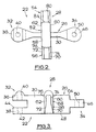
- Figure 2 is a plan view, on a larger scale, of one link of the chain; and
- Figure 3 is a side elevation of the link.
- In apparatus for conveying a powdery particulate feed material from a storage hopper to the birds in an intensive poultry house, a
feeding trough 10 extends along a required path through the house. The trough extends continuously from, and back to, the storage hopper. Anendless drag chain 12 lies in the bottom of thetrough 10, on aflat bottom surface 14 betweenupstanding side walls rotatable guide wheel 20 serves to guide the chain through the corner. - The chain is made up of
moulded plastics links 22 which are pivotally coupled together, end to end, by means of hardenedsteel pins 24. Each link, of which one is shown in detail in Figures 2 and 3, is a unitary moulding of an acetal plastics resin. The link is of cruciform shape as seen in plan, comprising a longitudinally-extendingbody 26 crossed centrally, and perpendicularly, by across-piece 28. - The
body 26 comprises a middle portion which is in the general form of anupstanding web 30 which at each end is thickened (widthwise of the link, as seen in Figure 2) to merge with first andsecond coupling formations first coupling formation 32 forms co-axially arranged upper andlower eyes apertures eyes slot 44 between them. Thesecond coupling formation 34 forms asingle eye 46 which is of similar thickness to the slot 44 (but not greater) and is at the same height as the slot above a flatcruciform bottom surface 48 of the link. Anaperture 50, similar to thealigned apertures eye 46 of the second coupling formation, the axes of the threeapertures flat bottom surface 48 of the link. - The
cross-piece 28 of the link, which extends equally to the two sides of thebody 26, comprises acentral portion 52 and twoend portions central portion 56 forms a drive shoulder presenting a semi-cylindrical convexuppermost surface 58, which in the axial direction extends longitudinally of the cross-piece, and which arcuately extends between first and second side faces 60 and 62 which are perpendicular to thebottom surface 48 of the link. Thesurface 58 projects above atop surface 64 of thebody 26. - The two
end portions lower portion 66 and a parallel-sidedupper portion 68. Thelower portion 66 comprises convergent first and second side faces 70 and 72; at thebottom surface 48, the lower portion is of the same width (i.e. measured lengthwise of the body 26) as thecentral portion 52 but the side faces 70 and 72 slope inwards, being equally but oppositely inclined to parallel planes perpendicular to thebottom surface 48. Theupper portion 68 comprises first and second side faces 74 and 76 which are in parallel with those planes, as seen in the drawings. - The form of the links, each comprising its
upstanding web 30 andcross-piece 28 of similar height, serves to create a grid which compartmentalises the trough space to inhibit flicking of the feed by the poultry, so reducing wastage of the feed. - In forming the
chain 12, thesingle eye 46 of each link is inserted into theslot 44 of a next link and acoupling pin 24 is inserted through the alignedapertures bottom surfaces 48 of the links lie flat on thebottom surface 14 of thetrough 10, the spacing between theside walls chain cross-pieces 28. The chain is so arranged to slide along the trough, pushing feed material along from the point of supply at the storage hopper by means, principally, of thecross-pieces 28. - The chain can be driven with equal effect in either direction, the first and second side faces 60, 70, 74 and 62, 72, 76, respectively, being arranged in the same way. The raked-back side faces 70 and 72, extending from lowermost edges of the cross-piece, are arranged to give a scraping action which resists any tendency for the links to ride over the feed in the trough.
- The chain can be driven by means of an overhead double sprocket wheel (not shown) engaging the half-round drive shoulders formed by the
central portions 52 of the links, the pairs of sprocket teeth straddling thebody web 30 of each link in turn to engage the drive shoulder to each side of the web. Theguide wheel 20, such as can be provided at each corner of the trough path, provides a lowercylindrical surface 78 to be engaged by end faces 80 of the link cross-pieces, and an uppercylindrical surface 82 of greater diameter to be engaged byend faces 84 of the drive shoulders, as can be seen in Figure 1.
Claims (7)
- A poultry feeding system comprising a storage hopper for feed, a flat-bottomed trough (10) extending from the hopper along a continuous path, and an endless drag chain (12) arranged to run along the bottom of the trough (10) to move feed released from the hopper along the trough, the chain (12) comprising links (22) which each comprise a longitudinally-extending body (26) traversed by a cross-piece (28) which extends between the side walls (16,18) of the trough (10) to push the feed along the trough, characterised in that the cross-pieces (28) present similar upstanding feed-engaging surfaces (70,72) on each of opposite sides, at least the lower portions of which are raked from the lowermost edges of the cross-piece (28) to provide a scraping action in sliding in either direction along the trough (10), upstanding bodies (26) and cross-pieces (28) of the chain forming a grid which compartmentalises the trough (10) to inhibit flicking of feed from the trough (10) by the poultry.
- A poultry feeding system according to claim 1 characterised in that the cross-pieces (28) of the links form drive shoulders (58) for engagement by a sprocket wheel arranged to drive the chain along the trough.
- A poultry feeding system according to either of claims 1 and 2 characterised in that each of the links (22) is cruciform.
- A poultry feeding system according to any one of claims 1 to 3 characterised in that the longitudinally-extending bodies (26) of the links comprise coupling formations (32, 34) enabling pivotal coupling of the links to one another in formation of the chain.
- A poultry feeding system according to claim 4 characterised in that a coupling formation (34) at one end of each link comprises an eye (46) and a coupling formation (32) at the other end of the link comprises a vertically-spaced pair of eyes (36,38), whereby the single eye (46) at said one end of a link in the chain is introduced between the pair of eyes (36, 38) at said other end of an adjacent link and the links coupled by means of a pin (24) inserted vertically through the three aligned eyes.
- A poultry feeding system according to any one claims 1 to 5 characterised in that each link (22) is a unitary moulding of a plastics material.
- A poultry feeding system according to any one of claims 1 to 6 characterised in that the chain is guided around a corner by a freely rotatable guide wheel (20) arranged to be engaged by end faces (80, 84) of the link cross-pieces (28).
Applications Claiming Priority (2)
| Application Number | Priority Date | Filing Date | Title |
|---|---|---|---|
| GB8805121 | 1988-03-03 | ||
| GB888805121A GB8805121D0 (en) | 1988-03-03 | 1988-03-03 | Drag chain for feeding particulate materials along trough |
Publications (3)
| Publication Number | Publication Date |
|---|---|
| EP0331473A2 EP0331473A2 (en) | 1989-09-06 |
| EP0331473A3 EP0331473A3 (en) | 1991-01-16 |
| EP0331473B1 true EP0331473B1 (en) | 1993-06-09 |
Family
ID=10632810
Family Applications (1)
| Application Number | Title | Priority Date | Filing Date |
|---|---|---|---|
| EP89302054A Expired - Lifetime EP0331473B1 (en) | 1988-03-03 | 1989-03-01 | Poultry feed conveyor |
Country Status (6)
| Country | Link |
|---|---|
| EP (1) | EP0331473B1 (en) |
| JP (1) | JPH0281816A (en) |
| DE (1) | DE68906927T2 (en) |
| ES (1) | ES2046465T3 (en) |
| GB (2) | GB8805121D0 (en) |
| ZA (1) | ZA891558B (en) |
Families Citing this family (7)
| Publication number | Priority date | Publication date | Assignee | Title |
|---|---|---|---|---|
| DE10022003A1 (en) * | 2000-05-05 | 2001-11-08 | Erich Stallkamp | Device for transporting and distribution of loose material such as chicken feed has stepped guide wheel with projection which at least partially fits over transporting chain housed in feed channel for material |
| CN102177856A (en) * | 2011-04-01 | 2011-09-14 | 安徽龙裕牧业设备有限公司 | Full-automatic feed conveying feed system |
| US11805759B2 (en) * | 2018-10-04 | 2023-11-07 | Gartech Equipments Pvt. Ltd. | Feeding system for poultry |
| CN112400746B (en) * | 2020-11-20 | 2022-05-31 | 安徽众盛农业发展有限公司 | A equipment for scattering fodder to meat chicken feeding trough |
| EP4360453A4 (en) * | 2021-06-22 | 2025-03-19 | Hytem Co., Ltd. | FEEDING TROUGH STRUCTURE AND FEEDING AID |
| CN118901599A (en) * | 2024-07-17 | 2024-11-08 | 黑龙江省农业机械工程科学研究院齐齐哈尔分院 | Intelligent mutton sheep feeding system |
| CN120573415B (en) * | 2025-08-05 | 2025-10-10 | 内蒙古伊东集团东兴化工有限责任公司 | Lime ball conveying system is pressed with lime to carbide production |
Family Cites Families (11)
| Publication number | Priority date | Publication date | Assignee | Title |
|---|---|---|---|---|
| US2754801A (en) * | 1951-09-17 | 1956-07-17 | Kenneth E Reese | Apparatus for conveying feed in a poultry house |
| US2699250A (en) * | 1952-01-23 | 1955-01-11 | Keen Mfg Corp | Conveyer |
| US2984338A (en) * | 1958-03-26 | 1961-05-16 | William W Pockman | Stock feeder |
| FR1228761A (en) * | 1959-06-29 | 1960-09-02 | Galvanisation Quimperoise | Improvements to automatic food displays, in particular usable as feed chains for poultry or other farm animals |
| FR77402E (en) * | 1960-01-22 | 1962-03-02 | Galvanisation Quimperoise | Improvements to automatic food displays, in particular usable as feed chains for poultry or other farm animals |
| GB1391623A (en) * | 1972-02-15 | 1975-04-23 | Palmaer K V | Link vonfiguration of drive chain |
| US4183430A (en) * | 1977-08-25 | 1980-01-15 | Hunter Mfg., Inc. | Grain handling flight conveyor assembly |
| NL185008C (en) * | 1979-01-18 | 1990-01-02 | Cehave Nv | TRAFFIC CHAIN WITH BRACKETS FOR A CHAIN TRANSPORTER. |
| US4518077A (en) * | 1982-08-23 | 1985-05-21 | Rexnord Inc. | Polymeric snap-through attachment for a hollow rivet chain |
| AU560688B2 (en) * | 1982-09-17 | 1987-04-16 | Fuller Company | Chain-conveyor link |
| EP0248969A1 (en) * | 1986-06-10 | 1987-12-16 | MILLE S.N.C. DI BORGHI LAURA & C. | Improved scraping conveyor chain |
-
1988
- 1988-03-03 GB GB888805121A patent/GB8805121D0/en active Pending
-
1989
- 1989-02-28 ZA ZA891558A patent/ZA891558B/en unknown
- 1989-03-01 GB GB8904607A patent/GB2216483A/en not_active Withdrawn
- 1989-03-01 ES ES198989302054T patent/ES2046465T3/en not_active Expired - Lifetime
- 1989-03-01 EP EP89302054A patent/EP0331473B1/en not_active Expired - Lifetime
- 1989-03-01 DE DE89302054T patent/DE68906927T2/en not_active Expired - Fee Related
- 1989-03-03 JP JP1051827A patent/JPH0281816A/en active Pending
Also Published As
| Publication number | Publication date |
|---|---|
| GB8904607D0 (en) | 1989-04-12 |
| EP0331473A2 (en) | 1989-09-06 |
| GB8805121D0 (en) | 1988-03-30 |
| DE68906927D1 (en) | 1993-07-15 |
| GB2216483A (en) | 1989-10-11 |
| EP0331473A3 (en) | 1991-01-16 |
| JPH0281816A (en) | 1990-03-22 |
| ES2046465T3 (en) | 1994-02-01 |
| DE68906927T2 (en) | 1994-01-13 |
| ZA891558B (en) | 1989-11-29 |
Similar Documents
| Publication | Publication Date | Title |
|---|---|---|
| EP0631950B1 (en) | Conveyor apparatus | |
| EP0212027B1 (en) | A method and device for distributively feeding articles | |
| US4171045A (en) | Raised link modular conveyor belt | |
| EP0352047B1 (en) | Method and apparatus for conveying materials | |
| US2784835A (en) | Skid-resistant conveyor belting | |
| US5947262A (en) | Conveyor with integrated self-actuating clamp | |
| EP0331473A2 (en) | Poultry feed conveyor | |
| US6343688B1 (en) | Conveyor and escalator for transporting eggs and the like | |
| US6079543A (en) | Lane-divided plastic conveyor belt | |
| DE3728853A1 (en) | MATERIAL TRANSPORT SYSTEM | |
| CA1107225A (en) | Scraper chain conveyor assembly | |
| GB1000748A (en) | Conveyor drive apparatus | |
| JPS5911487B2 (en) | transport equipment | |
| JPS6317712A (en) | Conveying element for multi-dimensional conveying device | |
| NZ509580A (en) | Conveyor belt for making pellets, with articulated transverse lamella | |
| US2699250A (en) | Conveyer | |
| EP0059840A3 (en) | Machine for stacking and packing flat articles | |
| EP1094018A1 (en) | Transport assembly | |
| EP0621851B1 (en) | Conveyor | |
| US11505409B2 (en) | Two-axis modular belt and conveyor | |
| RU2019477C1 (en) | Face flight conveyer | |
| EP0060009B2 (en) | A conveyor system | |
| EP0507413A1 (en) | Distributing conveyor | |
| US3262548A (en) | Flexible chain with bearing surfaces | |
| JPH0418969Y2 (en) |
Legal Events
| Date | Code | Title | Description |
|---|---|---|---|
| PUAI | Public reference made under article 153(3) epc to a published international application that has entered the european phase |
Free format text: ORIGINAL CODE: 0009012 |
|
| AK | Designated contracting states |
Kind code of ref document: A2 Designated state(s): BE DE ES FR GB NL SE |
|
| PUAL | Search report despatched |
Free format text: ORIGINAL CODE: 0009013 |
|
| AK | Designated contracting states |
Kind code of ref document: A3 Designated state(s): BE DE ES FR GB NL SE |
|
| 17P | Request for examination filed |
Effective date: 19910701 |
|
| 17Q | First examination report despatched |
Effective date: 19910814 |
|
| RAP3 | Party data changed (applicant data changed or rights of an application transferred) |
Owner name: UNIVERSITY OF WOLVERHAMPTON |
|
| GRAA | (expected) grant |
Free format text: ORIGINAL CODE: 0009210 |
|
| AK | Designated contracting states |
Kind code of ref document: B1 Designated state(s): BE DE ES FR GB NL SE |
|
| REF | Corresponds to: |
Ref document number: 68906927 Country of ref document: DE Date of ref document: 19930715 |
|
| ET | Fr: translation filed | ||
| REG | Reference to a national code |
Ref country code: ES Ref legal event code: FG2A Ref document number: 2046465 Country of ref document: ES Kind code of ref document: T3 |
|
| PLBE | No opposition filed within time limit |
Free format text: ORIGINAL CODE: 0009261 |
|
| STAA | Information on the status of an ep patent application or granted ep patent |
Free format text: STATUS: NO OPPOSITION FILED WITHIN TIME LIMIT |
|
| 26N | No opposition filed | ||
| PGFP | Annual fee paid to national office [announced via postgrant information from national office to epo] |
Ref country code: SE Payment date: 19950116 Year of fee payment: 7 |
|
| PGFP | Annual fee paid to national office [announced via postgrant information from national office to epo] |
Ref country code: BE Payment date: 19950117 Year of fee payment: 7 |
|
| EAL | Se: european patent in force in sweden |
Ref document number: 89302054.5 |
|
| PGFP | Annual fee paid to national office [announced via postgrant information from national office to epo] |
Ref country code: FR Payment date: 19950303 Year of fee payment: 7 |
|
| PGFP | Annual fee paid to national office [announced via postgrant information from national office to epo] |
Ref country code: ES Payment date: 19950316 Year of fee payment: 7 |
|
| PGFP | Annual fee paid to national office [announced via postgrant information from national office to epo] |
Ref country code: NL Payment date: 19950331 Year of fee payment: 7 |
|
| PGFP | Annual fee paid to national office [announced via postgrant information from national office to epo] |
Ref country code: DE Payment date: 19950526 Year of fee payment: 7 |
|
| PGFP | Annual fee paid to national office [announced via postgrant information from national office to epo] |
Ref country code: GB Payment date: 19960229 Year of fee payment: 8 |
|
| PG25 | Lapsed in a contracting state [announced via postgrant information from national office to epo] |
Ref country code: SE Effective date: 19960302 Ref country code: ES Free format text: LAPSE BECAUSE OF NON-PAYMENT OF DUE FEES Effective date: 19960302 |
|
| PG25 | Lapsed in a contracting state [announced via postgrant information from national office to epo] |
Ref country code: BE Effective date: 19960331 |
|
| BERE | Be: lapsed |
Owner name: UNIVERSITY OF WOLVERHAMPTON Effective date: 19960331 |
|
| PG25 | Lapsed in a contracting state [announced via postgrant information from national office to epo] |
Ref country code: NL Effective date: 19961001 |
|
| PG25 | Lapsed in a contracting state [announced via postgrant information from national office to epo] |
Ref country code: FR Effective date: 19961129 |
|
| NLV4 | Nl: lapsed or anulled due to non-payment of the annual fee |
Effective date: 19961001 |
|
| PG25 | Lapsed in a contracting state [announced via postgrant information from national office to epo] |
Ref country code: DE Effective date: 19961203 |
|
| EUG | Se: european patent has lapsed |
Ref document number: 89302054.5 |
|
| REG | Reference to a national code |
Ref country code: FR Ref legal event code: ST |
|
| PG25 | Lapsed in a contracting state [announced via postgrant information from national office to epo] |
Ref country code: GB Effective date: 19970301 |
|
| GBPC | Gb: european patent ceased through non-payment of renewal fee |
Effective date: 19970301 |
|
| REG | Reference to a national code |
Ref country code: ES Ref legal event code: FD2A Effective date: 19990405 |