EP0331428A2 - Verfahren und Gerät zur Erregung seismischer Wellen - Google Patents
Verfahren und Gerät zur Erregung seismischer Wellen Download PDFInfo
- Publication number
- EP0331428A2 EP0331428A2 EP89301972A EP89301972A EP0331428A2 EP 0331428 A2 EP0331428 A2 EP 0331428A2 EP 89301972 A EP89301972 A EP 89301972A EP 89301972 A EP89301972 A EP 89301972A EP 0331428 A2 EP0331428 A2 EP 0331428A2
- Authority
- EP
- European Patent Office
- Prior art keywords
- fluid
- housing
- end means
- oscillation
- water
- Prior art date
- Legal status (The legal status is an assumption and is not a legal conclusion. Google has not performed a legal analysis and makes no representation as to the accuracy of the status listed.)
- Withdrawn
Links
Images
Classifications
-
- G—PHYSICS
- G10—MUSICAL INSTRUMENTS; ACOUSTICS
- G10K—SOUND-PRODUCING DEVICES; METHODS OR DEVICES FOR PROTECTING AGAINST, OR FOR DAMPING, NOISE OR OTHER ACOUSTIC WAVES IN GENERAL; ACOUSTICS NOT OTHERWISE PROVIDED FOR
- G10K11/00—Methods or devices for transmitting, conducting or directing sound in general; Methods or devices for protecting against, or for damping, noise or other acoustic waves in general
- G10K11/02—Mechanical acoustic impedances; Impedance matching, e.g. by horns; Acoustic resonators
- G10K11/04—Acoustic filters ; Acoustic resonators
-
- G—PHYSICS
- G01—MEASURING; TESTING
- G01V—GEOPHYSICS; GRAVITATIONAL MEASUREMENTS; DETECTING MASSES OR OBJECTS; TAGS
- G01V1/00—Seismology; Seismic or acoustic prospecting or detecting
- G01V1/02—Generating seismic energy
- G01V1/133—Generating seismic energy using fluidic driving means, e.g. highly pressurised fluids; using implosion
- G01V1/135—Generating seismic energy using fluidic driving means, e.g. highly pressurised fluids; using implosion by deforming or displacing surfaces of enclosures, e.g. by hydraulically driven vibroseis™
Definitions
- This invention relates to a method and apparatus for generating seismic signals in the earth.
- an early technique of generating seismic signals in water covered environments was by using explosives.
- a major disadvantage with explosives was the risk of injury, and the resulting harm to sea life. Explosives were subsequently replaced by other less expensive and destructive sources.
- One such early seismic source was generally known as a sparker.
- a high voltage charge was generated between an anode and a cathode, generating an acoustic wave in the surrounding water.
- a major disadvantage in using sparkers again was safety. The required charge placed across the terminals was extremely high. Often crewmen were critically injured by exposed transmission lines or when the sparker misfired when being deployed or retrieved.
- a less expensive, more efficient and less hazardous seismic source was developed which operated on compressed air.
- a chamber in an air gun was pressurized to a predetermined point which depended upon the size of the chamber. Once the gun was pressurized, a quick acting valve was opened to the outside where the pressurized air explosively excited, generating a seismic signal in the water. The frequency of the signal could be controlled by providing specific air-gun volumes in combination. Air guns were very efficient for the period, and were much less hazardous than any previous seismic source. A disadvantage in using air guns was that the seismic signal signature was affected by the expanding bubbles (bubble pulse) once the air was ejected into the water.
- a seismic source based upon a similar premise was developed which used the medium in which it was disposed to cause the seismic signal.
- Water guns are hydraulically actuated devices which use water ejected at a high rate of speed to generate the seismic signal. The water is ejected as a unitary plug or slug which causes a cavitation in the water. Collapse of the cavitation causes the seismic signal.
- a disadvantage in using water guns is the frequency spectrum obtained. Just as when using air guns, many water guns must be combined to obtain the desired frequency spectrum. Another disadvantage is that the frequency can not be generated incrementally within a short period of time, similar to that obtained in vibratory seismic signal generators used on land.
- the present invention provides a method and apparatus for generating a seismic signal in the earth, the apparatus located within a body of water.
- a resonant standing wave is generated within a housing using a fluid.
- the apparatus can take various forms, two of which are described herein.
- a pair of resilient end members are positioned within the housing to effectively define a cavity therebetween; the end members being spaced apart by a predetermined distance.
- a fluid is contained by the housing and located between the two end members. The fluid is excited into oscillation by an actuator located within the cavity to produce a resonant standing wave.
- the created standing wave preferably is generated in whole or half wavelengths.
- a single resilient end member is spaced a predetermined distance from a non-resilient, non-compressible member defining a substantially similar cavity as mentioned above.
- the fluid located between the members is oscillated into resonance creating a standing wave as above, but produces a wave of quarter-wavelength increments.
- one-quarter, one-half, three-quarters and whole wavelengths may be created, depending on the length of the housing.
- This invention also provides in some embodiments a means for readily varying the resonant frequency of the standing wave over a period of time.
- the distance between the end members may be rapidly changed. The ability to change the distance provides a means for sweeping a range of frequencies or for generating several discreet frequencies as the operator desires.
- an acoustic source which is highly energy efficient can be provided. This results because a resonant wave requires only small amounts of energy to maintain the resonance. Another advantage is that the frequency of the aquatic seismic source may be readily changed within a short period of time. Yet another advantage is that the resonant signal generated by the source is extremely clean, containing essentially no noise resulting from the actual generation of the signal as do hydraulic or pneumatic seismic sources.
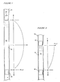
- a length of tubing 10 is substantially closed at one end by an end member, illustrated schematically as 12.
- a second end member 14 is located within the tube near the opposite end a preselect distance from end member 12. Both end members substantially seal the tubing 10.
- a fluid 16 is captured and maintained in the cavity 18 between end members 12 and 14.
- end members 12 and 14 should be resilient.
- at least one end member such as 14 should be rigid for reasons which will become apparent below.
- the described embodiment creates a desired acoustic impedance mismatch between the fluid 16 and the end members 12 and 14.
- end members 12 and 14 would have a lower acoustic impedance than the fluid 16.
- only one of the end members 12 or 14 should have an acoustic impedance greater than the fluid; the other end member should have an impedance lesser than the fluid.
- the end members 12 and 14 are spaced from one another so that when the fluid captured therebetween is excited into oscillation, a standing wave is generated in the fluid.
- the length of the longitudinal axis of the cavity 18 is shown along the line X.
- the numeral 0 indicates the location of the innermost side of one end member such as 12.
- the length along the longitudinal axis X, wherein the peak pressure amplitude occurs in a sinusoidal wave is indicated by the legend L which is equal to one-half X. Twice the distance L is the location where the pressure excursion decays to zero, which in resonance occurs at the inner surface of the opposite end member 14.
- fluid motion is zero at X equal to L, and maximum at X equal to zero and at X equal to twice L.
- fluid motion is zero at X equal to L and maximum at X equal that the oscillation frequency of the fluid 16 between the end members 12 and 14 may be varied by changing the distance between the end members.
- This frequency range is preferably from 5 hertz (Hz) up to and including 500 Hz. Frequencies below 5 Hz. may also be generated by this invention.
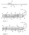
- FIG 3 is a general elevational illustration of a vessel towing a seismic streamer cable and at least one seismic source such as the one described herein.
- the Figure generally illustrates a ship 20 towing at least one seismic streamer cable 22 which contains a plurality of seismic sensors, each spaced at regular intervals along its length.
- At least one seismic source 24 is also shown being towed behind the ship 20 coupled by an umbilical 26.
- the seismic streamer cable 22 and the source 24 are typically towed at a predetermined depth below the water surface as is well known in the art.
- FIG 4 is an elevational view in cross-section of one embodiment of the seismic source utilizing the concept initially discussed above.
- the seismic source generally comprises an elongate tubular housing 28.
- the housing may have several coupling points located around the exterior such as the rings generally indicated as 29.
- the housing is open at each end so as to facilitate receipt and removal of a resonance generator generally indicated as 30 to be described below.
- the housing 28 is closed and made substantially fluidtight by end caps generally indicated as 32.
- At least one end cap contains a connector 34 for receiving an end of the umbilical 26 for coupling the source 24 and enclosed generator 30 to the vessel.
- the end caps 32 may be convex in shape to streamline the ends of the housing.
- the housing and the end caps may be constructed from stainless steel or other high strength material such as polyvinylchloride (PVC) plastics or aluminum.
- PVC polyvinylchloride
- the resonance generator 30 is generally comprised of a length of conduit 34 which is axially located within the housing 28.
- One end of the conduit 34 is coupled to the umbilical 26 and may contain a motor generally indicated as 36.
- the motor 36 may have a drive attached to a pulley 38 which is driven by hydraulic fluid, air or electricity supplied through the umbilical 26.
- the opposite end of the conduit 34 may have another pulley 40 attached thereto.
- Midway along the conduit 34 may be an actuator assembly 42 containing diaphragms or ports disposed about its circumference.
- On each side of the actuator assembly 42, and slidably received along the conduit 34 may be end members 44 and 46 similar to those described earlier in reference to Figure 1.
- Each end member 44 and 46 may be constructed of a resilient material such as rubber or plastic and define a bladder shown as 48 and filled with air or other fluid.
- the material comprising the end members and the amount of fluid contained therein may be determined based on the frequencies to be generated by one skilled in the art of acoustics.
- the end members 44 and 46 may be interconnected to each other by way of a cable 50 which passes around pulleys 38 and 40.
- the end members may be interconnected in such a manner by the cable 50 so they will move in opposite directions when the motor 36 is actuated, thus changing the volume of the cavity 18 between the end members.
- the actuator assembly 42 mentioned above may be of the type disclosed in the incorporated patents and applications mentioned above.
- the actuator assembly will not be described in detail.
- the actuator assembly may comprise a motor connected to a source of power through the umbilical 26.
- the motor may operate a piston within a chamber.
- the side of the piston which is in communication with the ports or diaphragms may be provided with a liquid such as hydraulic fluid.
- As the piston within the chamber is driven in reciprocating motion by the motor, it attempts to pump hydraulic fluid to and from the diaphragms and, hence, exert an alternating increased pressure and decreased pressure in the fluid 16.
- the movement of the diaphragms caused by the motor causes corresponding movement within the fluid between the end members 44 and 46.
- the frequency of those oscillations may be controlled so as to produce a resonant standing wave within the space between the end members 44 and 46.
- the distance between the end members 44 and 46 and the frequency of oscillation of the diaphragm may be chosen so that a standing full wave or half-wave may occur in the fluid between the two end members.
- An alternate actuator assembly 42 may comprise a spinning valve mechanism based on the principle disclosed in United States Patent Application 07/136,148.
- fluid is provided through the umbilical 26 to a rotating piston which is ported so as to direct fluid through ports defined in the exterior of the actuator.
- the piston rotates at a controlled rate, fluid is jetted through the ports into the surrounding fluid causing corresponding pressure pulsations.
- FIG. 5 is an elevational view in cross-section of another embodiment of the seismic source for carrying out the technique described earlier in Figure 2.
- a housing 28 substantially similar to that described above may be used, complete with the same end caps and umbilical attaching means.
- Extending along the axis of the housing 28 may be a shaft 54 threaded along its length.
- One end of the shaft is received in a bearing 56 concentrically located in one end cap 32.
- the other end of the shaft is coupled to a motor 58 located in the housing 28 and coupled via the umbilical 26 to the ship.
- Also located in the motor 58 may be an actuator similar to those described above, providing diaphragms or ports in the inside surface 60 of the motor 58.
- Both the motor 58 and the actuator 42 are in communication with the ship through the umbilical 26.
- the face 60 of the motor forms one end of the cavity 18, with the other end defined by an end member shown as 62 threadably received along the shaft 54.
- at least one end member should be resilient.
- end member 62 will be made of resilient material such as that mentioned above.
- the inside face 60 may also contain the resilient material. It is preferred that the end member 62 not rotate with respect to the housing 28.
- a groove may be longitudinally located along the circumference of the end member which receives a track defined along the inner surface of the housing 28.
Landscapes
- Engineering & Computer Science (AREA)
- Physics & Mathematics (AREA)
- Remote Sensing (AREA)
- Life Sciences & Earth Sciences (AREA)
- Acoustics & Sound (AREA)
- Geology (AREA)
- Environmental & Geological Engineering (AREA)
- General Life Sciences & Earth Sciences (AREA)
- General Physics & Mathematics (AREA)
- Geophysics (AREA)
- Multimedia (AREA)
- Geophysics And Detection Of Objects (AREA)
- Vibration Prevention Devices (AREA)
Applications Claiming Priority (2)
| Application Number | Priority Date | Filing Date | Title |
|---|---|---|---|
| US16227188A | 1988-02-29 | 1988-02-29 | |
| US162271 | 1988-02-29 |
Publications (2)
| Publication Number | Publication Date |
|---|---|
| EP0331428A2 true EP0331428A2 (de) | 1989-09-06 |
| EP0331428A3 EP0331428A3 (de) | 1990-05-09 |
Family
ID=22584920
Family Applications (1)
| Application Number | Title | Priority Date | Filing Date |
|---|---|---|---|
| EP89301972A Withdrawn EP0331428A3 (de) | 1988-02-29 | 1989-02-28 | Verfahren und Gerät zur Erregung seismischer Wellen |
Country Status (5)
| Country | Link |
|---|---|
| EP (1) | EP0331428A3 (de) |
| AU (1) | AU2599688A (de) |
| DK (1) | DK94589A (de) |
| NO (1) | NO885262L (de) |
| NZ (1) | NZ227142A (de) |
Cited By (4)
| Publication number | Priority date | Publication date | Assignee | Title |
|---|---|---|---|---|
| EP0393881A3 (de) * | 1989-04-21 | 1991-07-03 | British Gas plc | Seismische Pulserregung |
| FR2658304A1 (fr) * | 1990-02-14 | 1991-08-16 | Schlumberger Prospection | Source sismique de fond et procede de creation d'ondes acoustiques dans un puits de forage. |
| US5270985A (en) * | 1989-04-21 | 1993-12-14 | British Gas Plc | Seismic pulse generation |
| EP0765695A3 (de) * | 1992-05-11 | 1997-09-10 | Macrosonix Corp | Antriebssystem für akustischen Resonator |
Family Cites Families (2)
| Publication number | Priority date | Publication date | Assignee | Title |
|---|---|---|---|---|
| US4396088A (en) * | 1981-02-06 | 1983-08-02 | Exxon Production Research Co. | Flexible marine seismic source |
| US4671379A (en) * | 1985-09-03 | 1987-06-09 | Petrophysical Services, Inc. | Method and apparatus for generating seismic waves |
-
1988
- 1988-11-25 NO NO88885262A patent/NO885262L/no unknown
- 1988-11-28 AU AU25996/88A patent/AU2599688A/en not_active Abandoned
- 1988-11-30 NZ NZ22714288A patent/NZ227142A/en unknown
-
1989
- 1989-02-28 EP EP89301972A patent/EP0331428A3/de not_active Withdrawn
- 1989-02-28 DK DK94589A patent/DK94589A/da not_active Application Discontinuation
Cited By (7)
| Publication number | Priority date | Publication date | Assignee | Title |
|---|---|---|---|---|
| EP0393881A3 (de) * | 1989-04-21 | 1991-07-03 | British Gas plc | Seismische Pulserregung |
| GB2230859B (en) * | 1989-04-21 | 1993-02-10 | British Gas Plc | Seismic pulse generation |
| US5270985A (en) * | 1989-04-21 | 1993-12-14 | British Gas Plc | Seismic pulse generation |
| FR2658304A1 (fr) * | 1990-02-14 | 1991-08-16 | Schlumberger Prospection | Source sismique de fond et procede de creation d'ondes acoustiques dans un puits de forage. |
| EP0442812A1 (de) * | 1990-02-14 | 1991-08-21 | Schlumberger Limited | Seismische Bohrlochquelle und Verfahren zur Erzeugung von akustischen Wellen in einem Bohrloch |
| US5137109A (en) * | 1990-02-14 | 1992-08-11 | Schlumberger Technology Corporation | Method and apparatus for creating seismic waves in a borehole |
| EP0765695A3 (de) * | 1992-05-11 | 1997-09-10 | Macrosonix Corp | Antriebssystem für akustischen Resonator |
Also Published As
| Publication number | Publication date |
|---|---|
| EP0331428A3 (de) | 1990-05-09 |
| NZ227142A (en) | 1990-12-21 |
| DK94589A (da) | 1989-08-30 |
| NO885262L (no) | 1989-08-30 |
| DK94589D0 (da) | 1989-02-28 |
| NO885262D0 (no) | 1988-11-25 |
| AU2599688A (en) | 1989-08-31 |
Similar Documents
| Publication | Publication Date | Title |
|---|---|---|
| US4671379A (en) | Method and apparatus for generating seismic waves | |
| CA1163352A (en) | Tunable marine seismic source | |
| US3583677A (en) | Electro-mechanical transducer for secondary oil recovery | |
| AU2011264920B2 (en) | Marine mechanical seismic source | |
| US5132942A (en) | Low frequency electroacoustic transducer | |
| US4805727A (en) | Down hole periodic seismic generator | |
| US4396088A (en) | Flexible marine seismic source | |
| US4834210A (en) | Apparatus for generating seismic waves | |
| US4211301A (en) | Marine seismic transducer | |
| CA1223953A (en) | Distributed marine seismic source | |
| US6464035B1 (en) | Streamlined, readily towable marine seismic energy source for creating intense swept-frequency and pulse-coded signals in a body of water | |
| US3978940A (en) | Acoustic source | |
| US5080189A (en) | Electro-hydraulic dipole vibrator | |
| US6135234A (en) | Dual mode multiple-element resonant cavity piezoceramic borehole energy source | |
| EP0331428A2 (de) | Verfahren und Gerät zur Erregung seismischer Wellen | |
| CA1105124A (en) | Methods and apparatus for use in generating and transmitting acoustic signals | |
| US3077944A (en) | Pneumatic sound source | |
| CN1031282A (zh) | 一种用于改善由井中地震源产生的能量在地质构造中的传播效率的方法和装置 | |
| US3246289A (en) | Resonant underwater hydrodynamic acoustic projector | |
| US5894451A (en) | Impulsive snap-through acoustic pulse generator | |
| EP3470883B1 (de) | Schiffsvibrator mit kontinuierlicher resonanz | |
| US20250102692A1 (en) | Linear motor driving means for acoustic emitters | |
| US3430727A (en) | Seismic signal transducing apparatus | |
| US3351902A (en) | Underwater sound source | |
| US5225638A (en) | Hydrogen-oxygen acoustic logging device |
Legal Events
| Date | Code | Title | Description |
|---|---|---|---|
| PUAI | Public reference made under article 153(3) epc to a published international application that has entered the european phase |
Free format text: ORIGINAL CODE: 0009012 |
|
| AK | Designated contracting states |
Kind code of ref document: A2 Designated state(s): ES FR GB NL |
|
| PUAL | Search report despatched |
Free format text: ORIGINAL CODE: 0009013 |
|
| AK | Designated contracting states |
Kind code of ref document: A3 Designated state(s): ES FR GB NL |
|
| 17P | Request for examination filed |
Effective date: 19901101 |
|
| 17Q | First examination report despatched |
Effective date: 19910813 |
|
| STAA | Information on the status of an ep patent application or granted ep patent |
Free format text: STATUS: THE APPLICATION IS DEEMED TO BE WITHDRAWN |
|
| 18D | Application deemed to be withdrawn |
Effective date: 19911224 |