EP0331399A1 - A method of fragmentation blasting - Google Patents
A method of fragmentation blasting Download PDFInfo
- Publication number
- EP0331399A1 EP0331399A1 EP89301936A EP89301936A EP0331399A1 EP 0331399 A1 EP0331399 A1 EP 0331399A1 EP 89301936 A EP89301936 A EP 89301936A EP 89301936 A EP89301936 A EP 89301936A EP 0331399 A1 EP0331399 A1 EP 0331399A1
- Authority
- EP
- European Patent Office
- Prior art keywords
- holes
- blast
- blasting
- area
- void
- Prior art date
- Legal status (The legal status is an assumption and is not a legal conclusion. Google has not performed a legal analysis and makes no representation as to the accuracy of the status listed.)
- Withdrawn
Links
Images


Classifications
-
- F—MECHANICAL ENGINEERING; LIGHTING; HEATING; WEAPONS; BLASTING
- F42—AMMUNITION; BLASTING
- F42D—BLASTING
- F42D3/00—Particular applications of blasting techniques
- F42D3/04—Particular applications of blasting techniques for rock blasting
-
- F—MECHANICAL ENGINEERING; LIGHTING; HEATING; WEAPONS; BLASTING
- F42—AMMUNITION; BLASTING
- F42D—BLASTING
- F42D1/00—Blasting methods or apparatus, e.g. loading or tamping
Definitions
- This invention relates to a method of fragmentation blasting.
- blast area In fragmentation blasting, a number of blast holes are drilled in an area of rock, known as the blast area.
- the detonation of the explosive results in shock energy radiating out from the explosive energy source.
- this wave energy overcomes the compressive strength of the rock around the periphery of the shothole. This results in the rock being crushed to powder for several centimeters around the circumference of the shothole.
- the energy is not sufficient to overcome the compressive strength of the rock and is transmitted in wave form through the rock until it comes in contact with a 'free face', when it is refracted and reflected back into the rock as a tensile force.
- the refracted energy is dissipated from the 'free face' and is responsible for the spalling of the rock from the front of the face observed when blasting.
- the reflected energy waves travel back into the rock and as the tensile strength of rock is less than the compressive strength it results in the rock being cracked.
- the gas volume and heat generated by the explosion then expands into these cracks and propels the rock into the atmosphere.
- Blasting stone to reduce it to a desired size is a function of the amount of explosive energy applied to fragment the stone.
- the amount of explosive in relation to the amount of stone is termed the blasting ratio.
- the amount of explosive per unit volume of stone should be sufficient to reduce the rock to fragments of the desired size, namely 9" and less, but in practice, such a blasting ratio would produce a gas volume and amount of heat which would project its stone completely out of control with detriment to safety and loading.
- Another impractical method would be to drill small diameter blast holes in such a number that sufficient energy could be applied in a controlled manner but even if such could be done it would be uneconomic.
- the machinery for transporting the large initial fragments of stone to the primary crusher and the primary crusher itself are expensive items and savings in cost could be achieved if the initial fragments were already in the region of 15 cubic inches.
- a method of fragmentation blasting which includes the step of forming blast holes through the blast area and also void holes spaced between blast holes, whereby said void holes form free faces internally of the blasting area and will, in association with external free face retract and reflect energy waves as additional tensile forces to more fully fragment the stone.
- the method also includes the step of splitting the blast area on a plane at or adjacent to the floor bottom to induce an interface therebetween before fragmentation blasting takes place.
- the method also includes the step of pre-splitting the back and side face or faces of the blast area before fragmentation blasting takes place.
- the method includes the step of sequentially blasting the blast holes.
- Said sequential blasting preferably includes the steps of detonating in sequence the explosive material in individual blast holes.
- each blast hole Preferably also, separate quantities of explosive material are provided in each blast hole to form at least two spaced decks and preferably, each deck is ignited separately.
- the sequential blasting of individual blast holes and of the decks in each blast hole are controlled by a combination of short delay detonators and a sequential blasting machine.
- the numeral 10 denotes an end portion of a mass of rock 10A, the end portion 10 of which is to be quarried by fragmentation blasting, i.e. primary blasting, it is therefore known as the blast area.
- the blast area is firstly split from the quarry floor 11 of the rock mass. This operation is conducted prior to the primary blasting. It consists of drilling holes 12 on a plane as near as possible to the plane of the quarry floor 11 and to a depth equal to the desired depth D of the blast area. These holes are lightly loaded with explosives and detonated simultaneously to induce a crack between all holes. By inducing an interface 13 between the quarry floor 11 and the volume of rock in the blast area 10.-
- pre-splitting of the back and side face or faces may also be conducted prior to primary blasting (Fig. 2). This involves drilling holes 14 along the desired back and side line of the blast area 10 on single planes. These holes are loaded with explosives and detonated simultaneously. Thus a crack 15 is induced along the back and side wall of the blast area. By inducing this break, energy from the primary blast is not required to overcome the shear force necessary to shear the blast bulk stone away from the back and side wall.
- a pattern of substantially upright holes 16, 17 are drilled through the blast area, being slightly angled downwardly and forwardly. A selection of these holes 16 are loaded with explosive material, i e. blast holes while others 17 remain empty as 'void holes'.
- the tensile energy wave will not have dissapated as much energy in travelling through the rock if it has a shorter distance to travel.
- By drilling void holes 17 in the blast area 10 a greater area of 'free face' is available to the energy waves, i.e. the surface area of the circumference and length of the void holes becomes 'free face'.
- the geometry and balance of the void and primary blast holes 17, 16 will depend upon individual circumstances.
- the diameter of the void and blast holes will also depend upon individual circumstances.
- the void and blast holes have a diameter of 5 5 8 ".
- the depth of the void and primary blast holes will be such that they touch the plane of the horizontal pre-split holes. Explosive loading of the blast holes will require to be designed so that a balance and even distribution of energy is achieved.
- each blast hole 16 Arranged in each blast hole 16 are two or more spaced 'decks' of explosive packages or 'charge weights' 18.
- two decks per hole have been considered, but there may be more than two per hole provided there is sufficient distance between the decks to avoid sympathetic detonation.
- the energy should be applied to the rock in a uniform and balanced manner and, because of the increased blasting ratio, it should be applied at a speed which will minimise excessive projection of the stone.
- sequential blasting is applied where not only are the individual blast holes detonated on a separate time delay but there is a separate delay interval between decks in each hole.
- Sequential Blasting employs the use of an exploder which has an inbuilt facility to transmit electrical detonation pulses at a predetermined timing to initiate several blasting circuits.
- the diagram, Fig. 4 sets out a typical three row blast using standard sequential timing and will be familiar to those skilled in the art.
- the diagram shows 30 blast holes each containing two charge weights. It also shows the detonation delay time D and detonation firing time F (in milli seconds) of the two charge weights in each blast hole. From this it can be seen that the charges are detonated in sequence, there being in this example five circuits which are actuated in sequence, each, after the first circuit, commencing while the previous circuit is still proceeding through its sequence.
- the diagram also indicates the echelon line 20 and the echelon angle 21.
Abstract
The method of fragmentation blasting includes the step of forming blast holes (16) through a blast area (10) and also void holes (17) spaced between blast holes. The blast holes are charged with explosive material but the void holes are left empty to form free faces internally of the blasting area. Thus, the void holes will, in association with an external free face retract and reflect energy waves as additional tensile forces to more fully fragment the stone. Prior to forming the blast holes and void holes the blast area is split on a plane at or adjacent to the floor bottom to induce an interface between before fragmentation blasting takes place. This is done by drilling holes (12) on a plane as close as possible to that of the quarry floor (11) and loading the holes with explosive. Pre-splitting of the back and side face or faces of the blast area (10) may also be done before fragmentation blasting takes place. This is done by drilling new vertical holes (14) and loading the holes with explosive. The blast holes are charged and detonated sequentially blasting in sequence the explosive material in individual blast holes is detonated in sequence preferably separate quantities of explosive material are provided in each blast hole to form at least two spaced decks and each deck is ignited separately. The sequential blasting of individual blast holes and of the decks in each blast hole is controlled by a combination of short delay detonators and a sequential blasting machine. As a result of the void holes, the fragments of stone are small enough to eliminate the need for primary crushers and machinery for transporting large initial fragments to a primary crusher.
Description
- This invention relates to a method of fragmentation blasting.
- In fragmentation blasting, a number of blast holes are drilled in an area of rock, known as the blast area. The detonation of the explosive results in shock energy radiating out from the explosive energy source. Initially, this wave energy overcomes the compressive strength of the rock around the periphery of the shothole. This results in the rock being crushed to powder for several centimeters around the circumference of the shothole. At this stage the energy is not sufficient to overcome the compressive strength of the rock and is transmitted in wave form through the rock until it comes in contact with a 'free face', when it is refracted and reflected back into the rock as a tensile force. The refracted energy is dissipated from the 'free face' and is responsible for the spalling of the rock from the front of the face observed when blasting. The reflected energy waves travel back into the rock and as the tensile strength of rock is less than the compressive strength it results in the rock being cracked. The gas volume and heat generated by the explosion then expands into these cracks and propels the rock into the atmosphere.
- Blasting stone to reduce it to a desired size is a function of the amount of explosive energy applied to fragment the stone. The amount of explosive in relation to the amount of stone is termed the blasting ratio. By increasing the amount of explosive per unit volume of stone the fragmentation of the stone will increase.
- In theory, the amount of explosive per unit volume of stone should be sufficient to reduce the rock to fragments of the desired size, namely 9" and less, but in practice, such a blasting ratio would produce a gas volume and amount of heat which would project its stone completely out of control with detriment to safety and loading.
- Another impractical method would be to drill small diameter blast holes in such a number that sufficient energy could be applied in a controlled manner but even if such could be done it would be uneconomic.
- At present, economic fragmentation blasting produces fragmented stone of a size considerably greater than 15 cubic inches, and those stone fragments have to be transported to a primary crusher which reduces them to about 15 cubic inches. From the primary crusher the fragmented stone is transferred to a secondary crusher which reduces the fragments to the required size of 9 cubic inches and less.
- The machinery for transporting the large initial fragments of stone to the primary crusher and the primary crusher itself are expensive items and savings in cost could be achieved if the initial fragments were already in the region of 15 cubic inches.
- It is therefore an object of this invention to provide a method of fragmentation blasting which obviates or mitigates the aforementioned disadvantages.
- According to the present invention there is provided a method of fragmentation blasting which includes the step of forming blast holes through the blast area and also void holes spaced between blast holes, whereby said void holes form free faces internally of the blasting area and will, in association with external free face retract and reflect energy waves as additional tensile forces to more fully fragment the stone.
- Preferably, the method also includes the step of splitting the blast area on a plane at or adjacent to the floor bottom to induce an interface therebetween before fragmentation blasting takes place.
- Preferably also, the method also includes the step of pre-splitting the back and side face or faces of the blast area before fragmentation blasting takes place.
- Preferably also, the method includes the step of sequentially blasting the blast holes.
- Said sequential blasting preferably includes the steps of detonating in sequence the explosive material in individual blast holes.
- Preferably also, separate quantities of explosive material are provided in each blast hole to form at least two spaced decks and preferably, each deck is ignited separately.
- Preferably also the sequential blasting of individual blast holes and of the decks in each blast hole are controlled by a combination of short delay detonators and a sequential blasting machine.
- An embodiment of the present invention will now be described, by way of example, with reference to the accompanying drawings, in which:-
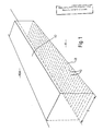
- Fig. 1 is a diagrammatic perspective view of a blast area showing the pre-splitting of the blast area at floor level.
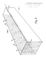
- Fig. 2 is a view similar to Fig. 1, but showing the pre-splitting of the blast area at the back and side face;
- Fig. 3 is a view similar to Fig. 1 but showing the blast and void holes; and
- Fig. 4 is a diagram in plan illustrating a sequential blasting operation.
- Referring firstly to Fig. 1, the
numeral 10 denotes an end portion of a mass ofrock 10A, theend portion 10 of which is to be quarried by fragmentation blasting, i.e. primary blasting, it is therefore known as the blast area. - The blast area is firstly split from the
quarry floor 11 of the rock mass. This operation is conducted prior to the primary blasting. It consists ofdrilling holes 12 on a plane as near as possible to the plane of thequarry floor 11 and to a depth equal to the desired depth D of the blast area. These holes are lightly loaded with explosives and detonated simultaneously to induce a crack between all holes. By inducing aninterface 13 between thequarry floor 11 and the volume of rock in the blast area 10.- - A. Energy from the primary blast is not required to overcome the shear force necessary to shear off the blast stone from the quarry floor.
- B. A uniform level plane for the loading machine to load is created. The breakout force required by the loading machine will be much less than with the conventional method.
- C. The need for subgrade drilling is eliminated, and
- D. The need for an explosive base charge is also eliminated.
- It must be stressed that accurate drilling is an essential factor at this stage of operation. Standard drilling equipment in its present form would not suffice.
- In addition to pre-splitting of the blast area at floor level, pre-splitting of the back and side face or faces may also be conducted prior to primary blasting (Fig. 2). This involves drilling
holes 14 along the desired back and side line of theblast area 10 on single planes. These holes are loaded with explosives and detonated simultaneously. Thus acrack 15 is induced along the back and side wall of the blast area. By inducing this break, energy from the primary blast is not required to overcome the shear force necessary to shear the blast bulk stone away from the back and side wall. - Referring now to Fig. 3, a pattern of substantially
upright holes holes 16 are loaded with explosive material, i e. blast holes whileothers 17 remain empty as 'void holes'. - Considering the mechanics by which explosives reduce the rock in size, the nearer the 'free face' is to the shock wave radiating from the shotholes the sooner these waves will be reflected as a tensile force. Thus the tensile energy wave will not have dissapated as much energy in travelling through the rock if it has a shorter distance to travel. By
drilling void holes 17 in the blast area 10 a greater area of 'free face' is available to the energy waves, i.e. the surface area of the circumference and length of the void holes becomes 'free face'. The geometry and balance of the void andprimary blast holes 
- Arranged in each
blast hole 16 are two or more spaced 'decks' of explosive packages or 'charge weights' 18. For the purpose of this embodiment, two decks per hole have been considered, but there may be more than two per hole provided there is sufficient distance between the decks to avoid sympathetic detonation. - To maximise the concept of the void holes, the energy should be applied to the rock in a uniform and balanced manner and, because of the increased blasting ratio, it should be applied at a speed which will minimise excessive projection of the stone. To do this sequential blasting is applied where not only are the individual blast holes detonated on a separate time delay but there is a separate delay interval between decks in each hole.
- Sequential Blasting employs the use of an exploder which has an inbuilt facility to transmit electrical detonation pulses at a predetermined timing to initiate several blasting circuits.
- Thus by using a combination of electric short delay detonators a sequential blasting machine the variation of delay timing available to balance a blast is far in excess of more normal blasting where the delay element is inherent in the detonator.
- The diagram, Fig. 4, sets out a typical three row blast using standard sequential timing and will be familiar to those skilled in the art. The diagram shows 30 blast holes each containing two charge weights. It also shows the detonation delay time D and detonation firing time F (in milli seconds) of the two charge weights in each blast hole. From this it can be seen that the charges are detonated in sequence, there being in this example five circuits which are actuated in sequence, each, after the first circuit, commencing while the previous circuit is still proceeding through its sequence. The diagram also indicates the
echelon line 20 and the echelon angle 21.
Claims (8)
1. A method of fragmentation blasting which includes the steps of forming blast holes through the blast area, charging the blast holes with explosive material and detonating the explosive material so that energy waves are retracted and reflected back from an external free face as tensile forces to fragment the stone, characterised in that void holes are formed between the blast holes whereby said void holes form free faces internally of the blasting area and will, in association with an external free face retract and reflect energy waves as additional tensile forces to more fully fragment the stone.
2. A method as claimed in claim 1, characterised by the step of splitting the blast area on a plane at or adjacent to the floor bottom to induce an interface therebetween before fragmentation blasting takes place.
3. A method as claimed in claim 1 or claim 2, characterised by the step of pre-splitting the back and side face or faces of the blast area before fragmentation blasting takes place.
4. A method as claimed in any one of claims 1 to 3 characterised in the step of sequentially blasting the blast holes.
5. A method as claimed in claim 4, characterised in that sequential blasting includes the steps of detonating in sequence the explosive material in individual blast holes.
6. A method as claimed in any one of claims 1 to 5, characterised in that separate quantities of explosive material are provided in each blast hole to form at least two spaced decks.
7. A method as claimed in claim 6, characterised in that each deck is ignited separately.
8. A method as claimed in any one of claimes 4 or 7 characterised in that the sequential blasting of individual blast holes is controlled by a combination of short delay detonators and a sequential blasting machine.
Applications Claiming Priority (2)
| Application Number | Priority Date | Filing Date | Title |
|---|---|---|---|
| GB8804635 | 1988-02-27 | ||
| GB888804635A GB8804635D0 (en) | 1988-02-27 | 1988-02-27 | Method of fragmentation blasting |
Publications (1)
| Publication Number | Publication Date |
|---|---|
| EP0331399A1 true EP0331399A1 (en) | 1989-09-06 |
Family
ID=10632497
Family Applications (1)
| Application Number | Title | Priority Date | Filing Date |
|---|---|---|---|
| EP89301936A Withdrawn EP0331399A1 (en) | 1988-02-27 | 1989-02-27 | A method of fragmentation blasting |
Country Status (2)
| Country | Link |
|---|---|
| EP (1) | EP0331399A1 (en) |
| GB (1) | GB8804635D0 (en) |
Cited By (7)
| Publication number | Priority date | Publication date | Assignee | Title |
|---|---|---|---|---|
| WO2001020248A1 (en) * | 1999-09-16 | 2001-03-22 | Dae Woo Kang | Method of blasting rock using air tubes charged in a blasthole |
| WO2002073120A1 (en) * | 2001-03-09 | 2002-09-19 | Brandrill Torrex (Proprietary) Limited | Mining method |
| WO2002101196A1 (en) * | 2001-06-12 | 2002-12-19 | Barry Anthony Hodgkinson | A method of excavating a hard material body |
| AU784685B2 (en) * | 2002-03-28 | 2006-06-01 | BELLAIRS, Jennifer Annette | A method of blasting |
| US20120242135A1 (en) * | 2009-09-29 | 2012-09-27 | Orica Explosives Technology Pty Ltd, | Method of underground rock blasting |
| CN112161538A (en) * | 2020-09-28 | 2021-01-01 | 中国建筑材料工业建设西安工程有限公司 | Complex mining area environment control blasting method |
| CN117072167A (en) * | 2023-08-28 | 2023-11-17 | 昆明理工大学 | Method and equipment for protecting reserved ore pillar by opening pre-cracks |
Citations (6)
| Publication number | Priority date | Publication date | Assignee | Title |
|---|---|---|---|---|
| US1205378A (en) * | 1916-01-22 | 1916-11-21 | Albert L Negstad | Automobile-brake. |
| US2609750A (en) * | 1946-05-16 | 1952-09-09 | Atlas Powder Co | Process of blasting |
| US2772632A (en) * | 1954-06-15 | 1956-12-04 | Union Carbide & Carbon Corp | Blasting of rock bodies |
| US3654866A (en) * | 1970-06-18 | 1972-04-11 | Hercules Inc | Mach effect in presplitting |
| US3877373A (en) * | 1969-11-19 | 1975-04-15 | Du Pont | Drill-and-blast process |
| US4690058A (en) * | 1986-04-09 | 1987-09-01 | C-I-L Inc. | Smooth wall blasting in rock |
-
1988
- 1988-02-27 GB GB888804635A patent/GB8804635D0/en active Pending
-
1989
- 1989-02-27 EP EP89301936A patent/EP0331399A1/en not_active Withdrawn
Patent Citations (6)
| Publication number | Priority date | Publication date | Assignee | Title |
|---|---|---|---|---|
| US1205378A (en) * | 1916-01-22 | 1916-11-21 | Albert L Negstad | Automobile-brake. |
| US2609750A (en) * | 1946-05-16 | 1952-09-09 | Atlas Powder Co | Process of blasting |
| US2772632A (en) * | 1954-06-15 | 1956-12-04 | Union Carbide & Carbon Corp | Blasting of rock bodies |
| US3877373A (en) * | 1969-11-19 | 1975-04-15 | Du Pont | Drill-and-blast process |
| US3654866A (en) * | 1970-06-18 | 1972-04-11 | Hercules Inc | Mach effect in presplitting |
| US4690058A (en) * | 1986-04-09 | 1987-09-01 | C-I-L Inc. | Smooth wall blasting in rock |
Cited By (10)
| Publication number | Priority date | Publication date | Assignee | Title |
|---|---|---|---|---|
| WO2001020248A1 (en) * | 1999-09-16 | 2001-03-22 | Dae Woo Kang | Method of blasting rock using air tubes charged in a blasthole |
| WO2002073120A1 (en) * | 2001-03-09 | 2002-09-19 | Brandrill Torrex (Proprietary) Limited | Mining method |
| WO2002101196A1 (en) * | 2001-06-12 | 2002-12-19 | Barry Anthony Hodgkinson | A method of excavating a hard material body |
| AU784685B2 (en) * | 2002-03-28 | 2006-06-01 | BELLAIRS, Jennifer Annette | A method of blasting |
| US20120242135A1 (en) * | 2009-09-29 | 2012-09-27 | Orica Explosives Technology Pty Ltd, | Method of underground rock blasting |
| US9243879B2 (en) * | 2009-09-29 | 2016-01-26 | Orica Explosives Technology Pty Ltd | Method of underground rock blasting |
| US9482507B2 (en) | 2009-09-29 | 2016-11-01 | Orica Explosives Technology Pty Ltd | Method of underground rock blasting |
| CN112161538A (en) * | 2020-09-28 | 2021-01-01 | 中国建筑材料工业建设西安工程有限公司 | Complex mining area environment control blasting method |
| CN117072167A (en) * | 2023-08-28 | 2023-11-17 | 昆明理工大学 | Method and equipment for protecting reserved ore pillar by opening pre-cracks |
| CN117072167B (en) * | 2023-08-28 | 2024-02-13 | 昆明理工大学 | Method for protecting reserved ore pillar by opening pre-cracks |
Also Published As
| Publication number | Publication date |
|---|---|
| GB8804635D0 (en) | 1988-03-30 |
Similar Documents
| Publication | Publication Date | Title |
|---|---|---|
| US7707939B2 (en) | Method of blasting | |
| EP3198218B1 (en) | Method of inter-hole delay blast | |
| Liu et al. | Numerical modelling of the effects of air decking/decoupling in production and controlled blasting | |
| US4248303A (en) | Explosive well-fracturing system | |
| US5415101A (en) | Shaped explosive charge, a method of blasting using the shaped explosive charge and a kit to make it | |
| EP0331399A1 (en) | A method of fragmentation blasting | |
| CA1259854A (en) | Smooth wall blasting in rock | |
| KR101696409B1 (en) | Paten using location difference of detonator explosive, and method for blasting | |
| EP3274555B1 (en) | System and method for underground blasting | |
| US3626850A (en) | Explosive assembly | |
| US4522448A (en) | Method and apparatus for reclamation by reducing highwalls to gradable rubble at augered or longwalled mining sites | |
| US20060027123A1 (en) | Explosive pressure wave concentrator | |
| RU2234673C1 (en) | Method of explosion of ascending wells | |
| Kulsrestha | Blasting Techniques to Reduce Insitu Rock Damage & Improving Highwall Stability | |
| Kalyan et al. | A study on various surface blast initiation systems | |
| CN112197659A (en) | Pit mining treatment method based on high and steep cliff wall | |
| RU2140055C1 (en) | Method for destruction of rocks | |
| Singh | Controlled blasting in quarries | |
| RU2112207C1 (en) | Method of forming of deep-hole charge | |
| RU2594236C1 (en) | Method for explosive destruction of various coherence rock massif with distributed and shortened blasthole charges with cumulative effect | |
| RU2232892C2 (en) | Method for cutting minerals at subterranean conditions | |
| RU2090830C1 (en) | Method of excitation of detonation wave in explosive charge | |
| RU2210671C2 (en) | Method of unloading of outburst-prone rock mass regions by blasting | |
| RU2086897C1 (en) | Charge for destruction of rock oversize | |
| Pearton | Evaluating the viability of pumpable emulsion explosives for use in narrow reef mining operations |
Legal Events
| Date | Code | Title | Description |
|---|---|---|---|
| PUAI | Public reference made under article 153(3) epc to a published international application that has entered the european phase |
Free format text: ORIGINAL CODE: 0009012 |
|
| AK | Designated contracting states |
Kind code of ref document: A1 Designated state(s): AT BE CH DE ES FR GB GR IT LI SE |
|
| 17P | Request for examination filed |
Effective date: 19900226 |
|
| 17Q | First examination report despatched |
Effective date: 19910704 |
|
| STAA | Information on the status of an ep patent application or granted ep patent |
Free format text: STATUS: THE APPLICATION IS DEEMED TO BE WITHDRAWN |
|
| 18D | Application deemed to be withdrawn |
Effective date: 19910829 |