EP0331349B1 - Protective screen for a visual display device - Google Patents
Protective screen for a visual display device Download PDFInfo
- Publication number
- EP0331349B1 EP0331349B1 EP89301761A EP89301761A EP0331349B1 EP 0331349 B1 EP0331349 B1 EP 0331349B1 EP 89301761 A EP89301761 A EP 89301761A EP 89301761 A EP89301761 A EP 89301761A EP 0331349 B1 EP0331349 B1 EP 0331349B1
- Authority
- EP
- European Patent Office
- Prior art keywords
- protective screen
- screen according
- filter layer
- screen
- intermediate member
- Prior art date
- Legal status (The legal status is an assumption and is not a legal conclusion. Google has not performed a legal analysis and makes no representation as to the accuracy of the status listed.)
- Expired - Lifetime
Links
Images
Classifications
-
- G—PHYSICS
- G06—COMPUTING OR CALCULATING; COUNTING
- G06F—ELECTRIC DIGITAL DATA PROCESSING
- G06F1/00—Details not covered by groups G06F3/00 - G06F13/00 and G06F21/00
- G06F1/16—Constructional details or arrangements
- G06F1/1601—Constructional details related to the housing of computer displays, e.g. of CRT monitors, of flat displays
- G06F1/1607—Arrangements to support accessories mechanically attached to the display housing
- G06F1/1609—Arrangements to support accessories mechanically attached to the display housing to support filters or lenses
-
- H—ELECTRICITY
- H04—ELECTRIC COMMUNICATION TECHNIQUE
- H04N—PICTORIAL COMMUNICATION, e.g. TELEVISION
- H04N5/00—Details of television systems
- H04N5/64—Constructional details of receivers, e.g. cabinets or dust covers
- H04N5/65—Holding-devices for protective discs or for picture masks
Definitions
- the present invention relates to a protective screen for a visual display unit with a cathode ray tube having a display surface and a body structure for the cathode ray tube.
- the screen compromises a filter layer which is operative for protection purposes, a support frame for the filter layer, fixing means for fixing the screen to the body structure and an intermediate member linking the fixing means and the support frame and enabling a pivot movement of the frame between a position covering the VDU display surface and a position out of the vicinity of the display surface.
- Cathode ray tubes of more modern display units have levels of electrostatic and electromagnetic fields and of other radiations which are generally considered not to be harmful. In order to lower the levels of the above-mentioned fields and residual radiations, it may be appropriate or it may be required by some health regulations to dispose in front of the display screen a protective screen which performs a filter function in regard to the electrostatic and electromagnetic fields and the residual radiation emitted by the cathode ray tube.
- VDU displays when VDU displays are viewed in daylight or particular other light conditions they may present reflections and glare which can be tiring for the operator. It may thus be appropriate or it may be required by some health regulations to dispose in front of the display screen an anti-reflection screen.
- GB-A-2 067 380 on which the preamble of claim 1 of this application is based, relates to an anti-reflection screen of this latter type, comprising a fine mesh of nylon supported by a flat framework.
- the screen may be attached to the structure of the cathode ray tube by means of a fastener carrying self-adhesive tape.
- the screen itself is linked to the fastener by two bendable metal strips which allow the screen to pivot upwards, away from and out of the vicinity of the VDU display.
- This screen has the disadvantage that it cannot be fastened to body structures of different shape. Moreover it is not suitable for multi-layer screens of heavy weight such as the protective screen necessary for optimizing filtering of electromagnetic fields and reflections.
- US-A-4,468,702 relates to a protective screen for a cathode ray tube (CRT) formed by a fabric mesh of conducting and non-conducting fibers affixed to a frame.
- the mesh is electrically connected to a grounding wire by means of a conductive glue.
- the screen is positioned adjacent to and touching the display surface of the CRT, although no method for so mounting the screen is described.
- US-A-3,952,152 describes a protective screen for a CRT which is permanently mounted between the body structure and the display surface of a CRT.
- This construction is expensive since it adds the cost of the screen to the cost of the display unit, even when the screen is not strictly necessary.
- this construction does not permit the protective screen to be removed from the display screen for cleaning the screen or to provide a better view of the images on the cathode ray tube.
- US 4712870 describes a Fresnel lens and filter supported in front of a VDU screen by means of an adjustable screw-clamp.
- the screw-clamp is fastened to the upper surface of the VDU housing and a bar extending from the combined Fresnel lens and filter is slidably mounted in the clamp.
- This mounting arrangement uses a rather long mounting bar and so allows the lens to be supported at some distance from the VDU screen and positioned in the line-of-sight of the VDU operator so as to magnify the image on the screen.
- the lens may need to be mounted rather above the height of the VDU screen to achieve this, which is enabled by pivoting the screw-clamp.
- the mounting arrangement is thus flexible but complicated, the screw-clamp alone comprising four separate components.
- the invention provides a protective screen for a VDU as defined in the appendant independent claim.
- Preferred features of the invention are defined in dependent subclaims.
- a protective screen according to the invention can be easily fixed to VDU body structures of different shapes and can be moved away from the VDU display to permit direct viewing of the VDU display.
- a protective screen 15 for a display unit (VDU) 16 comprises a filter layer 17 which is operative to provide the protection effect.
- the display unit 16 of known type is indicated in dash-dotted lines in the drawings and comprises cathode ray tube 18 having a display surface 19 and a body structure 20 for the cathode ray tube 18.
- the screen 15 comprises a support frame 21 for the filter layer 17, an intermediate support 22, adjustable fixing means 24 for fixing the intermediate support 22 to the upper portion of the body structure 20 and pivot means 26 between the frame 21 and the intermediate support 22 for pivoting the filter layer 17 with respect to the display surface 19 of the cathode ray tube 18 when the support 22 is fixed to the body structure 20.
- the frame 21 comprises two half shell portions 28 and 29 (see Figures 3 and 7) of plastics material which are provided with complementary coupling elements 31 and 32 respectively for interengagingly locking the shell portions 28 and 29 together, and ribs 30 on the shell portion 28 for correct positioning of the filter layer 17 between the two shell portions 28 and 29.
- the complementary elements 31 and 32 are introduced and locked relative to each other by means of a simple pressure.
- the two shell portions 28 and 29 are each of a C-shaped section.
- the outside edges of the shell portions 28 and 29 are in mutual contact and their inside edges are resiliently urged against the filter layer 17 in such a way as to compensate for any dimensional differences in the filter layer 17.
- the intermediate support 22 (see Figures 1, 3 and 4) is substantially centered with respect to the screen 15 and the body structure 20 of the VDU 16 and extends over a fraction, for example half, of the maximum width of the screen 15.
- the intermediate support 22 has an axis of symmetry 34 and a first adjustable fixing means 24 comprising a guide 36 extending front to back.
- a rectangular plate member 37 On the lower portion of the support 22, parallel to the axis 34, is a rectangular plate member 37 which is capable of being fixed to the body structure 20 of the VDU 16, for example by means of a double-sided adhesive pad 38.
- the plate member 37 is provided with a rib 39 (see Figure 5) extending front to back and carrying a cylindrical body 54 which can both slide in the guide 36, with freedom of front-to-back translatory movement with respect to the support 22, and freedom to turn about the axis of the cylinder (compare Figs. 5 and 6) in this way the screen 15 is capable of being disposed at the optimum distance from the surface 19 of the CRT 18, at a position corresponding to an optimised position for fixing of the plate member 37 to the body structure 20.
- the plate member 37 is disposed to the left side of the axis of symmetry 34 of the support 22.
- the fixing means 24 are completed by a second plate member 42 which is identical to the plate member 37 and which is disposed symmetrically to the plate member 37, with respect to the transverse axis of symmetry 34 of the support 22, and can also be fixed to the body structure 20 by means of a double-sided adhesive pad 38.
- the plate member 42 also comprises a rib 39 and a cylindrical body 54 by means of which it is slidable in a guide 43 on the support 22, which is identical to the guide 36 and which is disposed symmetrically to the guide 36 with respect to the axis 34.
- the body structures 20 have different curvatures.
- the guides 36 and 43 each comprise a central rib 48 which is parallel to the axis 34 and which projects from the lower portion of the support 22 and pairs of side flanges 51 and 52 which are parallel to the rib 48 and which, together with the terminal portion of the rib 48, define a corresponding cylindrical seat 53.
- Each coupling joint 46 and 47 comprises the cylindrical seat 53 of the support 22 and the cylindrical body 54 of the respective plate members 37 and 42.
- Each cylindrical body 54 is thus capable of sliding and rotating between the corresponding limbs 51 and 52 with freedom for translatory and rotational movement with respect to the intermediate support 22.
- the side flanges 51 and 52 are each provided with a projection 56 which defines a constriction 57 for the cylindrical body 54.
- the flanges 51 and 52 are also capable of resiliently yielding to permit each cylindrical body 54 to be snapped into position and removed therefrom by way of the constriction 57 of the flanges 51 and 52.
- the two ribs 48 are each toothed (58) along their length.
- a corresponding tooth 59 on each cylindrical body 54 is capable of co-operating with the teeth 58 with an interference fit, for the purposes of locking the plate members 37 and 42 in the desired position.
- Manual movement of the support 22 in a transverse direction will cause the teeth 58 to be ridden over, resulting in positioning in incremental steps of the support 22.
- the interengagement of the teeth 59 with the teeth 58 does not impede the rotary movement of the plate members 37 and 42 with respect to the support 22 and the dimensions of the teeth 59 are such as to guarantee coupling to the teeth 58 in all possible angular positions of the two plate members.
- the frame 21 (see Figure 1) is defined by four sides, to give a rectangular shape, in which the upper side and the lower side are longer than the other two sides when the screen 15 is mounted on the VDU 16.
- the upper side of the frame 21 comprises two lugs 61 and 62 which are provided on the outside shell portion 28.
- the two lugs 61 and 62 project upwardly from the upper side and with respect to the upper side of the inner shell portion 29 and define a rectangular space 63 in which the intermediate support 22 is housed.
- the support 22 (see Figure 3) comprises a plate of substantially parallelepipedic shape and which is downwardly hollow and which is defined by an upper plate 66, a pair of side walls 67 and a pair of front and rear walls 68.
- the pivot means 26 comprise two pairs of pivot seats 69 and corresponding pins 70 which are interposed between the side walls 67 of the support 22 and the projecting lugs 61 and 62 of the frame 21.
- a friction ring 71 (see Figure 8) of resiliently yielding material, for example rubber, is forced between each wall 67 of the support 22 and the projecting lug 61,62 of the frame 21 to permit the filter layer 17 to rotate with respect to the display surface of the CRT 18 in a damped fashion (see Figure 2).
- the frame 21 can assume a stable position affording total access to the surface 19 by virtue of a rotary movement of more than 180°, in which an upper edge 72 of the shell portion 28 of the frame 21, in the space 63, is arrested against the upper plate 66 of the support 22 in the position shown in dotted lines.
- the filter screen 17 In use the filter screen 17 remains, under the force of gravity, in a substantially vertical position, with an upper edge 73 (see Figure 3) of the shell portion 29 arrested against a vertically downwardly projecting limb 74 of the upper plate 66 of the support 22. Finally a damping block 75 (see Figure 2), for example of rubber, is disposed on the lower edge of the shell portion 29 and prevents damage to the screen 15 and the VDU 16 in the event that the filter layer 17 is moved violently towards the surface 19.
- the filter layer 17 which is known per se is transparent and has two metallised and transparent surface layers.
- the frame 21 is of insulating material and comprises a mounting 76 for a socket 77 (see Figure 9) of conductive material, provided with two resilient limbs 78 in electrical contact with the layer or the metallised layers of the filter layer 17.
- the socket 77 comprises a cylindrical opening 79 which is coaxial with an opening 81 of the mounting 76 to permit the introduction of a plug 82 into the opening 79, and in turn is capable of permitting an earthing connection for the filter layer 17 by means of a cable 83.
- the above-described protective screen is capable of being easily fixed to the body structure 20 of the VDU 16 and ensures that the filter layer 17 can be easily removed by rotary movement of the frame 21 about the pins 70 to the stable position shown in dotted lines in Figure 2.
Landscapes
- Engineering & Computer Science (AREA)
- General Engineering & Computer Science (AREA)
- Theoretical Computer Science (AREA)
- Multimedia (AREA)
- Signal Processing (AREA)
- Computer Hardware Design (AREA)
- Human Computer Interaction (AREA)
- Physics & Mathematics (AREA)
- General Physics & Mathematics (AREA)
- Devices For Indicating Variable Information By Combining Individual Elements (AREA)
- Transforming Electric Information Into Light Information (AREA)
- Liquid Crystal (AREA)
- Vessels, Lead-In Wires, Accessory Apparatuses For Cathode-Ray Tubes (AREA)
- Color Television Image Signal Generators (AREA)
- Indexing, Searching, Synchronizing, And The Amount Of Synchronization Travel Of Record Carriers (AREA)
- Holo Graphy (AREA)
- Helmets And Other Head Coverings (AREA)
- Illuminated Signs And Luminous Advertising (AREA)
- Fittings On The Vehicle Exterior For Carrying Loads, And Devices For Holding Or Mounting Articles (AREA)
- Electronic Switches (AREA)
- Facsimile Heads (AREA)
- Escalators And Moving Walkways (AREA)
- Display Devices Of Pinball Game Machines (AREA)
Abstract
Description
- The present invention relates to a protective screen for a visual display unit with a cathode ray tube having a display surface and a body structure for the cathode ray tube. The screen compromises a filter layer which is operative for protection purposes, a support frame for the filter layer, fixing means for fixing the screen to the body structure and an intermediate member linking the fixing means and the support frame and enabling a pivot movement of the frame between a position covering the VDU display surface and a position out of the vicinity of the display surface.
- Cathode ray tubes of more modern display units have levels of electrostatic and electromagnetic fields and of other radiations which are generally considered not to be harmful. In order to lower the levels of the above-mentioned fields and residual radiations, it may be appropriate or it may be required by some health regulations to dispose in front of the display screen a protective screen which performs a filter function in regard to the electrostatic and electromagnetic fields and the residual radiation emitted by the cathode ray tube.
- In addition, when VDU displays are viewed in daylight or particular other light conditions they may present reflections and glare which can be tiring for the operator. It may thus be appropriate or it may be required by some health regulations to dispose in front of the display screen an anti-reflection screen.
- GB-A-2 067 380, on which the preamble of
claim 1 of this application is based, relates to an anti-reflection screen of this latter type, comprising a fine mesh of nylon supported by a flat framework. The screen may be attached to the structure of the cathode ray tube by means of a fastener carrying self-adhesive tape. The screen itself is linked to the fastener by two bendable metal strips which allow the screen to pivot upwards, away from and out of the vicinity of the VDU display.
This screen has the disadvantage that it cannot be fastened to body structures of different shape. Moreover it is not suitable for multi-layer screens of heavy weight such as the protective screen necessary for optimizing filtering of electromagnetic fields and reflections. - US-A-4,468,702 relates to a protective screen for a cathode ray tube (CRT) formed by a fabric mesh of conducting and non-conducting fibers affixed to a frame. The mesh is electrically connected to a grounding wire by means of a conductive glue. The screen is positioned adjacent to and touching the display surface of the CRT, although no method for so mounting the screen is described.
- US-A-3,952,152 describes a protective screen for a CRT which is permanently mounted between the body structure and the display surface of a CRT. This construction is expensive since it adds the cost of the screen to the cost of the display unit, even when the screen is not strictly necessary. In addition this construction does not permit the protective screen to be removed from the display screen for cleaning the screen or to provide a better view of the images on the cathode ray tube.
- US 4712870 describes a Fresnel lens and filter supported in front of a VDU screen by means of an adjustable screw-clamp. The screw-clamp is fastened to the upper surface of the VDU housing and a bar extending from the combined Fresnel lens and filter is slidably mounted in the clamp. This mounting arrangement uses a rather long mounting bar and so allows the lens to be supported at some distance from the VDU screen and positioned in the line-of-sight of the VDU operator so as to magnify the image on the screen. The lens may need to be mounted rather above the height of the VDU screen to achieve this, which is enabled by pivoting the screw-clamp. The mounting arrangement is thus flexible but complicated, the screw-clamp alone comprising four separate components.
- The invention provides a protective screen for a VDU as defined in the appendant independent claim. Preferred features of the invention are defined in dependent subclaims.
- Advantageously, a protective screen according to the invention can be easily fixed to VDU body structures of different shapes and can be moved away from the VDU display to permit direct viewing of the VDU display.
- The invention will be described in more detail, by way of example, with reference to the accompanying drawings, in which:
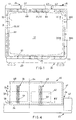
- Figure 1 is a diagrammatic view of the screen according to the invention in the position of use,
- Figure 2 is a side view of part of the screen shown in Figures 1,
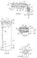
- Figure 3 shows some sectioned details of the screen shown in Figure 2, on an enlarged scale,
- Figure 4 is a plan view of part of some details of the screen shown in Figure 1, on an enlarged scale,
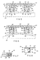
- Figure 5 shows details from Figure 4 in section taken along line V-V and on an enlarged scale,
- Figure 6 shows the details illustrated in Figure 5, in a second working position,
- Figure 7 shows other details from Figure 1 in section taken along line VII-VII and on an enlarged scale,
- Figure 8 shows further details from the screen illustrated in Figure 1, in section taken along line VIII-VIII in Figure 4,
- Figure 9 shows other details from Figure 1, in section taken along line IX-IX and on an enlarged scale, and
- Figure 10 is a front view of part of the structure shown in Figure 9.
- Referring to Figures 1, 2 and 3, a
protective screen 15 for a display unit (VDU) 16 comprises afilter layer 17 which is operative to provide the protection effect. Thedisplay unit 16 of known type is indicated in dash-dotted lines in the drawings and comprisescathode ray tube 18 having adisplay surface 19 and abody structure 20 for thecathode ray tube 18. - In accordance with the invention, the
screen 15 comprises asupport frame 21 for thefilter layer 17, anintermediate support 22, adjustable fixing means 24 for fixing theintermediate support 22 to the upper portion of thebody structure 20 and pivot means 26 between theframe 21 and theintermediate support 22 for pivoting thefilter layer 17 with respect to thedisplay surface 19 of thecathode ray tube 18 when thesupport 22 is fixed to thebody structure 20. - The
frame 21 comprises twohalf shell portions 28 and 29 (see Figures 3 and 7) of plastics material which are provided withcomplementary coupling elements shell portions shell portion 28 for correct positioning of thefilter layer 17 between the twoshell portions complementary elements shell portions shell portions filter layer 17 in such a way as to compensate for any dimensional differences in thefilter layer 17. - In use the intermediate support 22 (see Figures 1, 3 and 4) is substantially centered with respect to the
screen 15 and thebody structure 20 of theVDU 16 and extends over a fraction, for example half, of the maximum width of thescreen 15. Theintermediate support 22 has an axis of symmetry 34 and a first adjustable fixing means 24 comprising aguide 36 extending front to back. On the lower portion of thesupport 22, parallel to the axis 34, is arectangular plate member 37 which is capable of being fixed to thebody structure 20 of theVDU 16, for example by means of a double-sidedadhesive pad 38. Theplate member 37 is provided with a rib 39 (see Figure 5) extending front to back and carrying acylindrical body 54 which can both slide in theguide 36, with freedom of front-to-back translatory movement with respect to thesupport 22, and freedom to turn about the axis of the cylinder (compare Figs. 5 and 6) in this way thescreen 15 is capable of being disposed at the optimum distance from thesurface 19 of theCRT 18, at a position corresponding to an optimised position for fixing of theplate member 37 to thebody structure 20. - The
plate member 37 is disposed to the left side of the axis of symmetry 34 of thesupport 22. Thefixing means 24 are completed by asecond plate member 42 which is identical to theplate member 37 and which is disposed symmetrically to theplate member 37, with respect to the transverse axis of symmetry 34 of thesupport 22, and can also be fixed to thebody structure 20 by means of a double-sidedadhesive pad 38. Theplate member 42 also comprises arib 39 and acylindrical body 54 by means of which it is slidable in aguide 43 on thesupport 22, which is identical to theguide 36 and which is disposed symmetrically to theguide 36 with respect to the axis 34. - The
cylindrical bodies 54 of theplate members guides plate members intermediate support 22. That makes it possible to adjust the angular positions of the plate members to the particular shape of that part of the body structure of the VDU 16 to which the plate members are to be fixed, as can be seen in Figures 5 and 6. In Figures 5 and 6, thebody structures 20 have different curvatures. - The
guides central rib 48 which is parallel to the axis 34 and which projects from the lower portion of thesupport 22 and pairs ofside flanges rib 48 and which, together with the terminal portion of therib 48, define a correspondingcylindrical seat 53. Eachcoupling joint cylindrical seat 53 of thesupport 22 and thecylindrical body 54 of therespective plate members cylindrical body 54 is thus capable of sliding and rotating between thecorresponding limbs intermediate support 22. - The
side flanges projection 56 which defines aconstriction 57 for thecylindrical body 54. Theflanges cylindrical body 54 to be snapped into position and removed therefrom by way of theconstriction 57 of theflanges - The two
ribs 48 are each toothed (58) along their length. Acorresponding tooth 59 on eachcylindrical body 54 is capable of co-operating with theteeth 58 with an interference fit, for the purposes of locking theplate members support 22 in a transverse direction will cause theteeth 58 to be ridden over, resulting in positioning in incremental steps of thesupport 22. On the other hand, the interengagement of theteeth 59 with theteeth 58 does not impede the rotary movement of theplate members support 22 and the dimensions of theteeth 59 are such as to guarantee coupling to theteeth 58 in all possible angular positions of the two plate members. - The frame 21 (see Figure 1) is defined by four sides, to give a rectangular shape, in which the upper side and the lower side are longer than the other two sides when the
screen 15 is mounted on the VDU 16. The upper side of theframe 21 comprises twolugs outside shell portion 28. The twolugs inner shell portion 29 and define arectangular space 63 in which theintermediate support 22 is housed. - The support 22 (see Figure 3) comprises a plate of substantially parallelepipedic shape and which is downwardly hollow and which is defined by an
upper plate 66, a pair ofside walls 67 and a pair of front andrear walls 68. The pivot means 26 comprise two pairs ofpivot seats 69 and correspondingpins 70 which are interposed between theside walls 67 of thesupport 22 and the projectinglugs frame 21. A friction ring 71 (see Figure 8) of resiliently yielding material, for example rubber, is forced between eachwall 67 of thesupport 22 and the projectinglug frame 21 to permit thefilter layer 17 to rotate with respect to the display surface of theCRT 18 in a damped fashion (see Figure 2). In addition theframe 21 can assume a stable position affording total access to thesurface 19 by virtue of a rotary movement of more than 180°, in which anupper edge 72 of theshell portion 28 of theframe 21, in thespace 63, is arrested against theupper plate 66 of thesupport 22 in the position shown in dotted lines. - In use the
filter screen 17 remains, under the force of gravity, in a substantially vertical position, with an upper edge 73 (see Figure 3) of theshell portion 29 arrested against a vertically downwardly projectinglimb 74 of theupper plate 66 of thesupport 22. Finally a damping block 75 (see Figure 2), for example of rubber, is disposed on the lower edge of theshell portion 29 and prevents damage to thescreen 15 and theVDU 16 in the event that thefilter layer 17 is moved violently towards thesurface 19. - The
filter layer 17 which is known per se is transparent and has two metallised and transparent surface layers. Theframe 21 is of insulating material and comprises a mounting 76 for a socket 77 (see Figure 9) of conductive material, provided with tworesilient limbs 78 in electrical contact with the layer or the metallised layers of thefilter layer 17. Thesocket 77 comprises acylindrical opening 79 which is coaxial with anopening 81 of the mounting 76 to permit the introduction of aplug 82 into theopening 79, and in turn is capable of permitting an earthing connection for thefilter layer 17 by means of acable 83. - The above-described protective screen is capable of being easily fixed to the
body structure 20 of theVDU 16 and ensures that thefilter layer 17 can be easily removed by rotary movement of theframe 21 about thepins 70 to the stable position shown in dotted lines in Figure 2.
Claims (14)
- A protective screen for a visual display unit (16) comprising a cathode ray tube (18) having a display surface (19) and a body structure (20), said screen comprising;
a filter layer (17) which is operative for protection purposes;
a support frame (21) for the filter layer;
fixing means (37,42,38) for being fixed to the body structure; and
an intermediate member (22) linking the fixing means and the support frame and enabling a pivot movement of said frame away from and out of the vicinity of the display surface (19);
characterised by;
adjustment means (46,47) for adjusting the position of the screen relative to the fixing means, comprising two coupling bodies (54) on said fixing means slidingly engaged with two corresponding guide members (36,43) on said intermediate member (22), the coupling bodies being slidable within the guide members for a back and forth adjustment of the position of the intermediate member (22) and the protective screen with respect to the display surface (19) when in use, a first of the two guide members being parallel to and laterally spaced from the second of said two guide members. - A protective screen according to claim 1, characterised in that said intermediate member (22) is symmetrical about an axis of symmetry (34) and said first and second guide members (36,42) are disposed parallel to and on opposite sides of said axis of symmetry.
- A protective screen according to claim 1 or 2, characterised in that said fixing means (37,42,38) comprises two plate members (37,42) which can be individually fixed to the body structure (20) and in that said coupling bodies (54,54) can pivot within the guide members (36,43) in a plane parallel to the filter layer to accommodate the angular positions of the plate members (37,42) required for fixing to the body structure (20).
- A protective screen according to claim 3, characterised in that said coupling bodies project outwardly from said plates.
- A protective screen according to any of claims 1 to 4, characterised in that each guide member comprises a pair of flanges (51,52) and in that each corresponding coupling body (54) has a cylindrical portion capable of sliding and pivoting within said pair of flanges to permit translatory and rotational movement respectively.
- A protective screen according to claim 5, characterised in that said flanges (51,52) are resilient to permit snap insertion and removal of the cylindrical portions of each coupling body (54).
- A protective screen according to any preceding claim, characterised by resilient toothed positioning elements (58,59) between at least one coupling body (54) and the corresponding guide (36,43) for movement in incremental steps as between the intermediate member (22) and the fixing means (37,42,38).
- A protective screen according to any preceding claim, characterised in that at least one guide member and the corresponding coupling body carry mutually interengable means comprising resilient teeth (58,59) for releasably retaining the coupling body within the guide member in selected translational positions.
- A protective screen according to claim 5, characterised in that at least one guide member comprises a row of teeth along an edge of a rib extending parallel to said flanges, and the corresponding coupling body comprises a tooth on said cylindrical portion, the tooth extending circumferentially around the cylindrical portion sufficiently far to maintain engagement with said teeth of said guide member in all possible angular positions of the coupling body within the guide member.
- A protective screen according to any preceding claim, characterised in that said intermediate member (22) is of substantially parallelepipedal shape having an upper portion (66) and side portions (67,67).
- A protective screen according to claim 10, characterised in that the support frame (21) can pivot on the intermediate member (22) through pivot means (26) comprising two lugs (61,62) projecting from an upper portion of the support frame and spaced apart from each other, engaged with first and second pivotal couplings on the side portions (67,67) of said intermediate member.
- A protective screen according to claim 10 or 11, characterised in that said upper portion (66) and said side portions (67,67) define a downwardly hollow portion and wherein said first and second guide members (36,43) are located in said hollow portion.
- A protective screen according to claim 10 or 11, characterised in that said support frame is of rectangular shape with four sides of which one upper side of greater length comprises said two lugs and in which the first and second pivotal couplings are spaced apart a distance substantially equal to about a half of the length of said one upper side of greater length.
- A protective screen according to any preceding claim, characterised in that said filter layer (17) has at least one conductive surface and said support frame (21) is of insulating material and comprises a housing (81) in which there is provided a socket (77) of conductive material, which socket is in electrical contact with said conductive surface of the filter layer and is housed in said housing to permit a ground connection for said filter layer.
Applications Claiming Priority (2)
| Application Number | Priority Date | Filing Date | Title |
|---|---|---|---|
| IT5293388U | 1988-03-03 | ||
| IT8852933U IT214515Z2 (en) | 1988-03-03 | 1988-03-03 | PROTECTION SCREEN FOR DISPLAY |
Publications (3)
| Publication Number | Publication Date |
|---|---|
| EP0331349A2 EP0331349A2 (en) | 1989-09-06 |
| EP0331349A3 EP0331349A3 (en) | 1991-04-10 |
| EP0331349B1 true EP0331349B1 (en) | 1995-04-19 |
Family
ID=11278636
Family Applications (1)
| Application Number | Title | Priority Date | Filing Date |
|---|---|---|---|
| EP89301761A Expired - Lifetime EP0331349B1 (en) | 1988-03-03 | 1989-02-23 | Protective screen for a visual display device |
Country Status (13)
| Country | Link |
|---|---|
| US (1) | US5030882A (en) |
| EP (1) | EP0331349B1 (en) |
| JP (1) | JP3040112B2 (en) |
| AT (1) | ATE121583T1 (en) |
| AU (1) | AU627440B2 (en) |
| CA (1) | CA1323088C (en) |
| DE (1) | DE68922232T2 (en) |
| DK (1) | DK101289A (en) |
| ES (1) | ES2070903T3 (en) |
| IT (1) | IT214515Z2 (en) |
| NO (1) | NO173909C (en) |
| YU (1) | YU44689A (en) |
| ZA (1) | ZA89946B (en) |
Families Citing this family (68)
| Publication number | Priority date | Publication date | Assignee | Title |
|---|---|---|---|---|
| IT223018Z2 (en) * | 1990-10-03 | 1995-05-12 | Mas Plast Srl | MODULAR FRAME FOR THE CREATION OF SCREENING GROUPS OF RADIATIONS EMITTED BY EQUIPMENT WITH DIFFERENTLY SIZED VIDEO TERMINALS. |
| SE467334B (en) * | 1990-10-25 | 1992-06-29 | Mikael Aronowitsch | FIXING AND POSITIONING DEVICE FOR SCREEN FILTER |
| EP0506346A3 (en) * | 1991-03-29 | 1992-11-04 | Curtis Manufacturing Company, Inc. | Monitor filter holder and system |
| JP2582206Y2 (en) * | 1991-08-09 | 1998-09-30 | 新明和工業株式会社 | Monitor device on boarding bridge |
| WO1993014596A1 (en) * | 1992-01-09 | 1993-07-22 | Sunnyline Computer Products Gmbh | Display screen filter, especially for computers |
| US5227916A (en) * | 1992-05-13 | 1993-07-13 | Minnesota Mining And Manufacturing Company | Adjustable mounting mechanism for an optical filter screen |
| USD357470S (en) | 1992-09-04 | 1995-04-18 | Ergo View Technologies Corp. | Combined horizontal and vertical adjustable hinge mechanism and computer monitor filter |
| US6074789A (en) * | 1994-03-08 | 2000-06-13 | Philips Electronics N.A. Corp. | Method for producing phosphor screens, and color cathode ray tubes incorporating same |
| DE9407017U1 (en) * | 1994-04-27 | 1994-06-30 | Tornow, Volker, 63165 Mühlheim | Holding device for a screen filter for monitors |
| US5448405A (en) * | 1994-05-13 | 1995-09-05 | Allsop, Inc. | Glare filter |
| US5459527A (en) * | 1994-07-12 | 1995-10-17 | Lin; Ta C. | Filter screen for monitors |
| GB2301512A (en) * | 1995-05-30 | 1996-12-04 | Horng Technical Enterprise Co | A pivotable protective screen frame structure |
| IT235996Y1 (en) | 1995-12-22 | 2000-07-18 | Baltea Spa | PROTECTION SCREEN ADAPTABLE TO DIFFERENT DIMENSION VIDEO UNITS |
| US5841227A (en) * | 1996-01-24 | 1998-11-24 | Terpin; David J. | Radiation shield with opaque and transparent portion |
| US6619799B1 (en) * | 1999-07-02 | 2003-09-16 | E-Vision, Llc | Optical lens system with electro-active lens having alterably different focal lengths |
| US7023594B2 (en) | 2000-06-23 | 2006-04-04 | E-Vision, Llc | Electro-optic lens with integrated components |
| US6517203B1 (en) | 1999-07-02 | 2003-02-11 | E-Vision, Llc | System, apparatus, and method for correcting vision using electro-active spectacles |
| US6986579B2 (en) * | 1999-07-02 | 2006-01-17 | E-Vision, Llc | Method of manufacturing an electro-active lens |
| US6871951B2 (en) | 2000-06-23 | 2005-03-29 | E-Vision, Llc | Electro-optic lens with integrated components |
| US6491391B1 (en) | 1999-07-02 | 2002-12-10 | E-Vision Llc | System, apparatus, and method for reducing birefringence |
| US6857741B2 (en) * | 2002-01-16 | 2005-02-22 | E-Vision, Llc | Electro-active multi-focal spectacle lens |
| US6733130B2 (en) | 1999-07-02 | 2004-05-11 | E-Vision, Llc | Method for refracting and dispensing electro-active spectacles |
| US6491394B1 (en) | 1999-07-02 | 2002-12-10 | E-Vision, Llc | Method for refracting and dispensing electro-active spectacles |
| US20090103044A1 (en) * | 1999-07-02 | 2009-04-23 | Duston Dwight P | Spectacle frame bridge housing electronics for electro-active spectacle lenses |
| US7775660B2 (en) * | 1999-07-02 | 2010-08-17 | E-Vision Llc | Electro-active ophthalmic lens having an optical power blending region |
| US7988286B2 (en) | 1999-07-02 | 2011-08-02 | E-Vision Llc | Static progressive surface region in optical communication with a dynamic optic |
| US7264354B2 (en) | 1999-07-02 | 2007-09-04 | E-Vision, Llc | Method and apparatus for correcting vision using an electro-active phoropter |
| US6851805B2 (en) * | 1999-07-02 | 2005-02-08 | E-Vision, Llc | Stabilized electro-active contact lens |
| US20070258039A1 (en) * | 1999-07-02 | 2007-11-08 | Duston Dwight P | Spectacle frame bridge housing electronics for electro-active spectacle lenses |
| US7404636B2 (en) | 1999-07-02 | 2008-07-29 | E-Vision, Llc | Electro-active spectacle employing modal liquid crystal lenses |
| US7290875B2 (en) * | 2004-11-02 | 2007-11-06 | Blum Ronald D | Electro-active spectacles and method of fabricating same |
| US7604349B2 (en) | 1999-07-02 | 2009-10-20 | E-Vision, Llc | Static progressive surface region in optical communication with a dynamic optic |
| US7290876B2 (en) * | 1999-07-02 | 2007-11-06 | E-Vision, Llc | Method and system for electro-active spectacle lens design |
| US6765550B2 (en) * | 2001-04-27 | 2004-07-20 | International Business Machines Corporation | Privacy filter apparatus for a notebook computer display |
| JP2005505789A (en) * | 2001-10-05 | 2005-02-24 | イー・ビジョン・エルエルシー | Hybrid electroactive lens |
| KR100468771B1 (en) * | 2002-10-10 | 2005-01-29 | 삼성전자주식회사 | Method for manufacturing MOS transistor |
| CA2535905A1 (en) | 2003-08-15 | 2005-02-24 | E-Vision, Llc | Enhanced electro-active lens system |
| EP1528802B1 (en) * | 2003-10-29 | 2011-02-23 | Thomson Licensing | Display apparatus with shielding |
| CA2563115A1 (en) * | 2004-04-13 | 2005-10-27 | Arizona Board Of Regents On Behalf Of The University Of Arizona | Patterned electrodes for electroactive liquid-crystal ophthalmic devices |
| US20050237485A1 (en) * | 2004-04-21 | 2005-10-27 | Blum Ronald D | Method and apparatus for correcting vision |
| US9801709B2 (en) | 2004-11-02 | 2017-10-31 | E-Vision Smart Optics, Inc. | Electro-active intraocular lenses |
| BRPI0518058A (en) * | 2004-11-02 | 2008-10-28 | E-Vision Llc | electro-spectacles and manufacturing methods |
| US8778022B2 (en) | 2004-11-02 | 2014-07-15 | E-Vision Smart Optics Inc. | Electro-active intraocular lenses |
| US8915588B2 (en) | 2004-11-02 | 2014-12-23 | E-Vision Smart Optics, Inc. | Eyewear including a heads up display |
| US20070159562A1 (en) * | 2006-01-10 | 2007-07-12 | Haddock Joshua N | Device and method for manufacturing an electro-active spectacle lens involving a mechanically flexible integration insert |
| US9092189B2 (en) * | 2006-04-26 | 2015-07-28 | Hewlett-Packard Development Company, L.P. | Privacy screen mounting system |
| US20080273166A1 (en) | 2007-05-04 | 2008-11-06 | William Kokonaski | Electronic eyeglass frame |
| WO2008105780A2 (en) | 2006-05-24 | 2008-09-04 | Pixeloptics, Inc. | Optical rangefinder for an electro-active lens |
| CA2656267A1 (en) | 2006-06-23 | 2008-01-03 | Pixeloptics, Inc. | Electronic adapter for electro-active spectacle lenses |
| US20080100792A1 (en) * | 2006-10-27 | 2008-05-01 | Blum Ronald D | Universal endpiece for spectacle temples |
| AR064985A1 (en) | 2007-01-22 | 2009-05-06 | E Vision Llc | FLEXIBLE ELECTROACTIVE LENS |
| AU2008218240B2 (en) | 2007-02-23 | 2014-01-30 | E-Vision Smart Optics, Inc. | Ophthalmic dynamic aperture |
| US7883206B2 (en) * | 2007-03-07 | 2011-02-08 | Pixeloptics, Inc. | Multifocal lens having a progressive optical power region and a discontinuity |
| US7883207B2 (en) | 2007-12-14 | 2011-02-08 | Pixeloptics, Inc. | Refractive-diffractive multifocal lens |
| US20080273169A1 (en) | 2007-03-29 | 2008-11-06 | Blum Ronald D | Multifocal Lens Having a Progressive Optical Power Region and a Discontinuity |
| WO2008110072A1 (en) * | 2007-03-09 | 2008-09-18 | Shenzhen Pchood Technology Co., Ltd. | Lens hood for display |
| JP4616857B2 (en) * | 2007-03-29 | 2011-01-19 | 技嘉科技股▲ふん▼有限公司 | Clamp mechanism |
| US11061252B2 (en) | 2007-05-04 | 2021-07-13 | E-Vision, Llc | Hinge for electronic spectacles |
| US10613355B2 (en) | 2007-05-04 | 2020-04-07 | E-Vision, Llc | Moisture-resistant eye wear |
| US12572035B2 (en) | 2007-05-04 | 2026-03-10 | E-Vision Optics, Llc | Moisture-resistant eye wear |
| US8317321B2 (en) * | 2007-07-03 | 2012-11-27 | Pixeloptics, Inc. | Multifocal lens with a diffractive optical power region |
| BRPI0908992A2 (en) | 2008-03-18 | 2015-11-24 | Pixeloptics Inc | advanced electro-active optical device |
| US8154804B2 (en) | 2008-03-25 | 2012-04-10 | E-Vision Smart Optics, Inc. | Electro-optic lenses for correction of higher order aberrations |
| US12436411B2 (en) | 2010-07-02 | 2025-10-07 | E-Vision Optics, Llc | Moisture-resistant eye wear |
| US12510773B2 (en) | 2011-02-11 | 2025-12-30 | E-Vision Optics, Llc | Moisture-resistant eye wear |
| KR102276220B1 (en) | 2012-01-06 | 2021-07-13 | 이-비전 스마트 옵틱스, 아이엔씨. | Eyewear docking station and electronic module |
| ES2861520T3 (en) | 2016-04-12 | 2021-10-06 | E Vision Smart Optics Inc | Electroactive lenses with high resistive bridges |
| US10599006B2 (en) | 2016-04-12 | 2020-03-24 | E-Vision Smart Optics, Inc. | Electro-active lenses with raised resistive bridges |
Family Cites Families (9)
| Publication number | Priority date | Publication date | Assignee | Title |
|---|---|---|---|---|
| US2067320A (en) * | 1935-10-17 | 1937-01-12 | American Telephone & Telegraph | Measuring system for program circuit maintenance |
| US3952152A (en) * | 1974-10-29 | 1976-04-20 | Teletype Corporation | CRT shield |
| JPS5521264Y2 (en) * | 1974-12-17 | 1980-05-22 | ||
| DE2642508C2 (en) * | 1976-09-22 | 1978-10-26 | Philips Patentverwaltung Gmbh, 2000 Hamburg | Television receiver housing and use of such a housing |
| SE7907065L (en) * | 1979-08-23 | 1981-02-24 | Erik Wessman | ANTI-REFLECTION DEVICE FOR DATA AND RADAR SCREEN SCREENS |
| US4468702A (en) * | 1982-04-16 | 1984-08-28 | Daca International B.V. | Radiation and static electricity suppression device |
| US4712870A (en) * | 1986-04-03 | 1987-12-15 | Robinson Donald L | Fresnell lens and filter for use with computers and the like |
| US4652085A (en) * | 1986-04-07 | 1987-03-24 | Selling Harley M | Dark room safe light filter assembly for a TV set |
| US4788597A (en) * | 1988-02-23 | 1988-11-29 | Sun-Flex Company Incorporated | Removable conforming video display terminal filter |
-
1988
- 1988-03-03 IT IT8852933U patent/IT214515Z2/en active
-
1989
- 1989-02-01 AU AU28983/89A patent/AU627440B2/en not_active Ceased
- 1989-02-07 ZA ZA89946A patent/ZA89946B/en unknown
- 1989-02-22 NO NO890760A patent/NO173909C/en unknown
- 1989-02-23 ES ES89301761T patent/ES2070903T3/en not_active Expired - Lifetime
- 1989-02-23 AT AT89301761T patent/ATE121583T1/en active
- 1989-02-23 EP EP89301761A patent/EP0331349B1/en not_active Expired - Lifetime
- 1989-02-23 DE DE68922232T patent/DE68922232T2/en not_active Expired - Fee Related
- 1989-03-01 YU YU00446/89A patent/YU44689A/en unknown
- 1989-03-01 CA CA000592450A patent/CA1323088C/en not_active Expired - Fee Related
- 1989-03-02 DK DK101289A patent/DK101289A/en not_active IP Right Cessation
- 1989-03-03 JP JP01051833A patent/JP3040112B2/en not_active Expired - Lifetime
- 1989-03-03 US US07/318,257 patent/US5030882A/en not_active Expired - Fee Related
Also Published As
| Publication number | Publication date |
|---|---|
| ATE121583T1 (en) | 1995-05-15 |
| DE68922232T2 (en) | 1995-08-31 |
| EP0331349A3 (en) | 1991-04-10 |
| ES2070903T3 (en) | 1995-06-16 |
| NO173909B (en) | 1993-11-08 |
| EP0331349A2 (en) | 1989-09-06 |
| JPH01310386A (en) | 1989-12-14 |
| DK101289A (en) | 1989-09-04 |
| AU2898389A (en) | 1989-09-07 |
| DE68922232D1 (en) | 1995-05-24 |
| CA1323088C (en) | 1993-10-12 |
| YU44689A (en) | 1992-02-20 |
| NO173909C (en) | 1994-02-16 |
| NO890760L (en) | 1989-09-04 |
| US5030882A (en) | 1991-07-09 |
| IT8852933V0 (en) | 1988-03-03 |
| DK170453B1 (en) | 1995-09-04 |
| JP3040112B2 (en) | 2000-05-08 |
| NO890760D0 (en) | 1989-02-22 |
| AU627440B2 (en) | 1992-08-27 |
| ZA89946B (en) | 1989-12-27 |
| IT214515Z2 (en) | 1990-05-09 |
| DK101289D0 (en) | 1989-03-02 |
Similar Documents
| Publication | Publication Date | Title |
|---|---|---|
| EP0331349A2 (en) | Protective screen for a visual display device | |
| US5533206A (en) | Welding helmet with removable electronic quick change cartridge | |
| US5448405A (en) | Glare filter | |
| CA2119500A1 (en) | Shielded Electrical Connector | |
| US6448893B1 (en) | Multifunction display arrangement for a motor vehicle | |
| US5673431A (en) | Face mask safety shield | |
| CN111929905B (en) | Upset supporting mechanism and double-deck bandage formula head-mounted apparatus | |
| EA035657B1 (en) | Apparatus for protecting eyes from radiation | |
| GB9116542D0 (en) | Filter adapter for panel mounted coaxial connectors | |
| CN214037712U (en) | Mounting assembly of pan-tilt camera and pan-tilt camera | |
| JPH04271997A (en) | Pilot helmet | |
| CN212466531U (en) | 3D eyesight training equipment | |
| CN109330840B (en) | Eye training instrument | |
| CN210573295U (en) | Data acquisition control device based on industrial Internet of things | |
| US7008233B1 (en) | Retractable panel interface cable device and method | |
| CN217607876U (en) | Head-mounted display device experience sharing frame | |
| CN206789209U (en) | A kind of Quick Release frame for seamless spliced screen | |
| CN215994026U (en) | Beam limiting device | |
| CN215833695U (en) | Optical machine device for head-mounted display equipment and optical machine module | |
| CN212614729U (en) | Development machine | |
| CN212342298U (en) | Radiation protection screen | |
| CN210056698U (en) | Eye training instrument | |
| CN210056697U (en) | Eye training instrument | |
| CN217820097U (en) | CT detector and corresponding CT machine | |
| CN223864692U (en) | Anti-reflection instrument panel for electric vehicle |
Legal Events
| Date | Code | Title | Description |
|---|---|---|---|
| PUAI | Public reference made under article 153(3) epc to a published international application that has entered the european phase |
Free format text: ORIGINAL CODE: 0009012 |
|
| AK | Designated contracting states |
Kind code of ref document: A2 Designated state(s): AT BE CH DE ES FR GB LI NL SE |
|
| PUAL | Search report despatched |
Free format text: ORIGINAL CODE: 0009013 |
|
| AK | Designated contracting states |
Kind code of ref document: A3 Designated state(s): AT BE CH DE ES FR GB LI NL SE |
|
| 17P | Request for examination filed |
Effective date: 19911003 |
|
| 17Q | First examination report despatched |
Effective date: 19930809 |
|
| GRAA | (expected) grant |
Free format text: ORIGINAL CODE: 0009210 |
|
| AK | Designated contracting states |
Kind code of ref document: B1 Designated state(s): AT BE CH DE ES FR GB LI NL SE |
|
| REF | Corresponds to: |
Ref document number: 121583 Country of ref document: AT Date of ref document: 19950515 Kind code of ref document: T |
|
| REF | Corresponds to: |
Ref document number: 68922232 Country of ref document: DE Date of ref document: 19950524 |
|
| REG | Reference to a national code |
Ref country code: ES Ref legal event code: FG2A Ref document number: 2070903 Country of ref document: ES Kind code of ref document: T3 |
|
| ET | Fr: translation filed | ||
| PGFP | Annual fee paid to national office [announced via postgrant information from national office to epo] |
Ref country code: AT Payment date: 19960213 Year of fee payment: 8 |
|
| PLBE | No opposition filed within time limit |
Free format text: ORIGINAL CODE: 0009261 |
|
| STAA | Information on the status of an ep patent application or granted ep patent |
Free format text: STATUS: NO OPPOSITION FILED WITHIN TIME LIMIT |
|
| 26N | No opposition filed | ||
| PGFP | Annual fee paid to national office [announced via postgrant information from national office to epo] |
Ref country code: BE Payment date: 19960412 Year of fee payment: 8 |
|
| PG25 | Lapsed in a contracting state [announced via postgrant information from national office to epo] |
Ref country code: AT Effective date: 19970223 |
|
| PG25 | Lapsed in a contracting state [announced via postgrant information from national office to epo] |
Ref country code: BE Effective date: 19970228 |
|
| BERE | Be: lapsed |
Owner name: BALTEA S.P.A. Effective date: 19970228 |
|
| PGFP | Annual fee paid to national office [announced via postgrant information from national office to epo] |
Ref country code: SE Payment date: 20010206 Year of fee payment: 13 |
|
| PGFP | Annual fee paid to national office [announced via postgrant information from national office to epo] |
Ref country code: FR Payment date: 20010213 Year of fee payment: 13 |
|
| PGFP | Annual fee paid to national office [announced via postgrant information from national office to epo] |
Ref country code: ES Payment date: 20010214 Year of fee payment: 13 |
|
| PGFP | Annual fee paid to national office [announced via postgrant information from national office to epo] |
Ref country code: GB Payment date: 20010221 Year of fee payment: 13 Ref country code: DE Payment date: 20010221 Year of fee payment: 13 |
|
| PGFP | Annual fee paid to national office [announced via postgrant information from national office to epo] |
Ref country code: NL Payment date: 20010228 Year of fee payment: 13 |
|
| PGFP | Annual fee paid to national office [announced via postgrant information from national office to epo] |
Ref country code: CH Payment date: 20010302 Year of fee payment: 13 |
|
| REG | Reference to a national code |
Ref country code: GB Ref legal event code: IF02 |
|
| PG25 | Lapsed in a contracting state [announced via postgrant information from national office to epo] |
Ref country code: GB Free format text: LAPSE BECAUSE OF NON-PAYMENT OF DUE FEES Effective date: 20020223 |
|
| PG25 | Lapsed in a contracting state [announced via postgrant information from national office to epo] |
Ref country code: SE Free format text: LAPSE BECAUSE OF NON-PAYMENT OF DUE FEES Effective date: 20020224 |
|
| PG25 | Lapsed in a contracting state [announced via postgrant information from national office to epo] |
Ref country code: ES Free format text: LAPSE BECAUSE OF NON-PAYMENT OF DUE FEES Effective date: 20020225 |
|
| PG25 | Lapsed in a contracting state [announced via postgrant information from national office to epo] |
Ref country code: LI Free format text: LAPSE BECAUSE OF NON-PAYMENT OF DUE FEES Effective date: 20020228 Ref country code: CH Free format text: LAPSE BECAUSE OF NON-PAYMENT OF DUE FEES Effective date: 20020228 |
|
| PG25 | Lapsed in a contracting state [announced via postgrant information from national office to epo] |
Ref country code: NL Free format text: LAPSE BECAUSE OF NON-PAYMENT OF DUE FEES Effective date: 20020901 |
|
| PG25 | Lapsed in a contracting state [announced via postgrant information from national office to epo] |
Ref country code: DE Free format text: LAPSE BECAUSE OF NON-PAYMENT OF DUE FEES Effective date: 20020903 |
|
| EUG | Se: european patent has lapsed |
Ref document number: 89301761.6 |
|
| REG | Reference to a national code |
Ref country code: CH Ref legal event code: PL |
|
| GBPC | Gb: european patent ceased through non-payment of renewal fee |
Effective date: 20020223 |
|
| PG25 | Lapsed in a contracting state [announced via postgrant information from national office to epo] |
Ref country code: FR Free format text: LAPSE BECAUSE OF NON-PAYMENT OF DUE FEES Effective date: 20021031 |
|
| NLV4 | Nl: lapsed or anulled due to non-payment of the annual fee |
Effective date: 20020901 |
|
| REG | Reference to a national code |
Ref country code: FR Ref legal event code: ST |
|
| REG | Reference to a national code |
Ref country code: ES Ref legal event code: FD2A Effective date: 20030922 |