EP0331273A2 - Swingable junction for blind track - Google Patents
Swingable junction for blind track Download PDFInfo
- Publication number
- EP0331273A2 EP0331273A2 EP89300023A EP89300023A EP0331273A2 EP 0331273 A2 EP0331273 A2 EP 0331273A2 EP 89300023 A EP89300023 A EP 89300023A EP 89300023 A EP89300023 A EP 89300023A EP 0331273 A2 EP0331273 A2 EP 0331273A2
- Authority
- EP
- European Patent Office
- Prior art keywords
- junction assembly
- corner junction
- tracks
- traveller
- blind
- Prior art date
- Legal status (The legal status is an assumption and is not a legal conclusion. Google has not performed a legal analysis and makes no representation as to the accuracy of the status listed.)
- Granted
Links
Images


Classifications
-
- E—FIXED CONSTRUCTIONS
- E06—DOORS, WINDOWS, SHUTTERS, OR ROLLER BLINDS IN GENERAL; LADDERS
- E06B—FIXED OR MOVABLE CLOSURES FOR OPENINGS IN BUILDINGS, VEHICLES, FENCES OR LIKE ENCLOSURES IN GENERAL, e.g. DOORS, WINDOWS, BLINDS, GATES
- E06B9/00—Screening or protective devices for wall or similar openings, with or without operating or securing mechanisms; Closures of similar construction
- E06B9/24—Screens or other constructions affording protection against light, especially against sunshine; Similar screens for privacy or appearance; Slat blinds
- E06B9/26—Lamellar or like blinds, e.g. venetian blinds
- E06B9/36—Lamellar or like blinds, e.g. venetian blinds with vertical lamellae ; Supporting rails therefor
Landscapes
- Engineering & Computer Science (AREA)
- Structural Engineering (AREA)
- Architecture (AREA)
- Civil Engineering (AREA)
- Blinds (AREA)
- Mutual Connection Of Rods And Tubes (AREA)
- Details Of Indoor Wiring (AREA)
- Drawers Of Furniture (AREA)
- Holders For Apparel And Elements Relating To Apparel (AREA)
Abstract
Description
- The invention relates to a blind apparatus and, in particular to a corner junction assembly for use in connecting two adjacent lengths of blind track.
- Vertical slat blinds are well known and comprise a track having a plurality of blind travellers movable therealong. Vertical blind slats are suspended from the travellers. The travellers can be drawn to and fro along the track, and the individual blind slats can be rotated so as to open or close the blinds.
- Traveller operating or control means extend along the track and hang downwardly from one end of the track.
- The installation of two or more lengths of blind track, which meet at a corner, presents certain problems, particularly in the arrangements for the traveller control means.
- One form of arrangement for such a corner junction assembly is described in U.S. Letters Patent 4,653,564, dated March 31, 1987 - Inventor Norbert Marocco, entitled "Track for Blinds."
- Using the system disclosed in the aforesaid patent, it is possible to joint the two tracks at a corner and to provide for the traveller control means to extend around the corner. In this way, the traveller control means, that is to say both the traveller moving means and also the blind slat rotation means, can be located at one end of one length of the track, and all of the blind travellers in both lengths of track can be operated simultaneously.
- The system disclosed in the aforesaid patent has proved to be highly satisfactory in use, and has achieved considerable commercial success.
- However, certain problems have arisen as a result of the experience of using the aforesaid system. In particular, it is desirable to have a corner junction assembly which is capable of hinging or swinging, and then being set in a desired angle, so as to fit a particular window, or other installation.
- One form of corner junction means is shown in the aforesaid patent and has proved to be satisfactory. However, it incorporates several different components which must be assembled together during assembly of the blind and this may, in practice, require a certain amount of skill. In addition, the practice for assembling such blinds is to, first of all, assemble the lengths of track in the factory, and set them at the correct angle. The traveller operating means are then adjusted as to length so as to extend around the correct arc at each corner.
- Once all of this has been done, the blind installation is then disassembled and shipped but then must be reassembled on the customer's premises.
- In order to do this satisfactorily it is desirable to have a corner junction assembly which can be preset at a predetermined angle, so that when disassembled and then reassembled, it will go together in the correct fashion.
- It is also desirable that the corner junction assembly shall be as short as possible. In blinds of this type, the blind slats are moved along the separate lengths of track in separate groups, although they are in fact moved simultaneously. When drawn fully to one side, the blind slats will hang, in groups, at the ends of their respective lengths of track. In order to avoid obstructing the ends of the tracks, it is thus desirable that the corner junction assembly at the ends of the tracks shall be as short as possible.
- With a view to overcoming the various problems listed above, the invention comprises a corner junction assembly for use in association with two adjacent blind tracks, such tracks each being adapted to carry slat-carrying travellers and each having at least one movable traveller control means, the corner junction assembly comprising at least one bearing ring means; at least one bearing hub means making a captive frictional fit within the bearing ring means to permit relative rotation thereof; track engagement means connected to respective ones of the bearing ring means and the bearing hub means for engagement with adjacent ends of respective ones of the tracks; and at least one movement transmission means adapted to be coupled to and to transmit movement from the traveller control means in one of the blind tracks to the traveller control means in the other of the blind tracks.
- Usefully, a corner junction assembly in accordance with this invention comprises upper and lower bearing ring means and upper and lower bearing hub means, the upper bearing hub means making a captive frictional fit within the upper bearing ring means and the lower bearing hub means making a captive frictional fit within the lower bearing ring means, and the upper and lower bearing ring means being spaced apart.
- Such a corner junction assembly is usefully provided with an opening in one of the upper and lower bearing hub means and a removable closure means is provided for closing the opening.
- In accordance with a particularly preferred feature of this invention, a corner junction assembly in accordance therewith includes a downwardly dependent arcuate cup member formed integrally with the upper bearing hub means, and a bearing surface of corresponding shape is formed on the upper bearing ring means to guidingly engage the exterior of the cup member.
- Such a cup member is usefully formed with a plurality of fracture lines parallel to one another at spaced intervals therearound, whereby portions of the cup member may be broken away during installation of the corner junction assembly with the blind tracks to accommodate different angular positions of those blind tracks.
- The bearing hub means of a corner junction assembly in accordance with this invention is usefully formed with a locking ring making a captive pressure fit within the bearing ring means.
- In one embodiment of a corner junction assembly according to the invention, the movement transmission means comprises at least one length of control cord integrally formed with control cords in each of the tracks and constituting the aforementioned traveller control means, as well as at least one pulley for guiding such length of the control cord. In one particular embodiment, such pulleys are mounted externally on the corner junction assembly.
- Another embodiment of a corner junction assembly according to the invention is intended for use with blind tracks in which the traveller control means are rotationally mounted and in such an embodiment such movement transmission means is adapted to transmit rotational movement between the traveller control means of the two blind tracks. Such a rotatable mounted movement transmission means can comprise a flexible coupling and at least one bearing means supporting the flexible coupling.
- Usefully, such a flexible coupling is adapted to be connected to the traveller control means for conjoint rotation therewith but in such a manner that axial movement of the flexible coupling relative to at least one of the traveller control means is possible to accommodate different angular positions of the blind tracks.
- In another embodiment, such rotatably mounted movement transmission means comprises interengaged gear means adapted to be secured to ends of the traveller control means of the blind tracks for conjoint rotation therewith. In one embodiment, such gear means are adapted to be secured to the ends of the traveller control means for conjoint rotation therewith while permitting axial movement of the gears means relative to at least one of the traveller control means to accommodate different angular positions of the tracks.
- Spring means are usefully provided to maintain such gear means in engagement with each other regardless of the relative angular positions of the tracks. If, however, such gear means are disposed for rotational movement through a rotational axial position of the corner junction assembly, then there is no need for relative axial movement of the gear means and the traveller control means during movement of the blind tracks into different angular positions.
- The various features of novelty which characterize the invention are pointed out with more particularity in the claims annexed to and forming a part of this disclosure. For a better understanding of the invention, its operating advantages and specific objects attained by its use, reference should be had to the accompanying drawings and descriptive matter in which there are illustrated and described preferred embodiments of the invention.
- The invention will now be described merely by way of illustration with reference to the accompanying drawings in which:
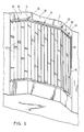
- Figure 1 is a general perspective illustration of one embodiment of a blind installation or apparatus in accordance with this invention, and shown as extending along three walls which meet at two corners;
- Figure 2 is a bottom plan view, looking upwardly of one embodiment of a corner junction assembly as used in the blind assembly as shown in Figure 1 and with certain parts omitted to reveal its internal construction;
- Figure 3 is a sectional view when taken as indicated by the arrows 3-3 of Figure 2;
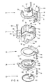
- Figure 4 is an exploded perspective illustration of the corner junction assembly shown in Figures 1 to 3;
- Figure 5 is a cut-away perspective view of the same corner junction assembly with certain parts omitted;
- Figure 6 is a schematic perspective view of one embodiment of a traveller and traveller control means used in the blind installation shown in the preceding figures;
- Figure 7 is a schematic perspective view of a second embodiment of a traveller and control means which can be used in a blind installation in accordance with this invention;
- Figure 8 is a perspective exploded illustration of a flexible coupling for use in a corner junction assembly in accordance with this invention;
- Figure 9 is a perspective illustration of an alternative form of coupling for use in this invention;
- Figure 10 is an exploded sectional view when taken as indicated by the arrows 10-10 of Figure 9;
- Figure 11 is a rear perspective illustration of an alternative embodiment of a corner junction assembly in accordance with this invention; and
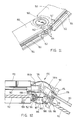
- Figure 12 is a sectional view through another embodiment of a corner junction assembly in accordance with this invention.
- Referring first of all to Figure 1, it will be seen that the invention is illustrated therein as a blind installation mounted in a situation in which there are three wall surfaces indicated generally as W, meeting at two corners indicated generally as C.
- Typically, this represents a bay window installation. However, blinds may be used in bay windows, or may be used to cover other openings or other surfaces, and the invention is not to be taken as exclusively limited to use in association with bay windows or, in fact, windows of an kind.
- A plurality, in this case, three, lengths of blind tracks generally indicated at 10, are shown mounted on the walls W, with the three lengths of
track 10 meeting at the two corners C. - From the tracks 10 a plurality of
slats 12 hang downwardly from thetravellers 14. - Traveller control means are provided which, in this embodiment of the invention, are indicated as the control or
pull cord 16 and thecontrol rod 18. Thecord 16 hangs downwardly at one end of one of thetracks 10 and is operative to move theslats 12 along thetracks 10. Thecontrol rod 18 is rotatable by movement of acontrol chain 19 to adjust the angular position of theslats 12 relative to thetracks 10. The hanging portion of thecord 16 and thecontrol chain 19 are shown in a horizontal position in Figure 2 to clarify their functions. - It will be appreciated that the showing of a
control cord 16 and acontrol rod 18 are merely illustrated as the traveller control means in general. Various different designs of traveller control means are possible and the invention is not intended to be restricted to any particular form of traveller control means. - The
tracks 10 andslats 12 may be of entirely conventional construction, such as are well known in the art and are made by a number of different manufacturers and are not, therefore, described in any detail, for the sake of clarity. - As shown generally in Figure 1, the three lengths of
blind track 10 are joined at the two corners C by means of corner junction assemblies in accordance with this invention and as indicated generally at 20. - Referring now to Figure 4, the
corner junction assembly 20 in accordance with the invention will be seen to comprise five separate moulded components, namely an upper bearing ring member or means 22, an upper bearing hub member or means 24, a lower bearing ring member or means 26, a lower bearing hub member or means 28, and a closure means orplate 30, provided for the sake of appearance. - Upper
bearing ring member 22 comprises a generally annular bearing means 32, and an upstandingannular wall 34, forming an L-shaped structure in section. - Along one side of the junction between the bearing means 32 and the
wall 34, there is formed a downwardlydependent end plate 36, with a guidance opening or bearing 38 formed therethrough. - A pair of generally rectangular track engagement means or mounting
block members 40 are also integrally formed with the upperbearing ring member 22 and extend more or less normal thereto on either side of theplate 36 to defineopenings 41 on either side thereof. - A bearing surface or
arcuate guidance cuff 42 is formed integrally with one ofblock members 40 and the annular bearing means 32. Aguidance pulley 43 is mounted on aguidance wedge portion 44 formed integrally with the other ofblocks 40. Ascrew receiving recess 45 is formed incuff 42. - The upper
bearing hub member 24 comprises anannular bearing hub 46, having an upper free edge terminating in alocking ring 48.Hub 46 andring 48 are intended to make a snap fit through the bearing means 32, and to be rotatable therein. - A flat disc-
like plate 50 is formed integrally with the lower edge of the bearinghub 46. A generally partially cylindrically shaped downwardly dependent wall orcup member 52 extends downwardly from the perimeter ofplate 50, thus forming what may be called an inverted cup-shaped structure. - Fracture or break lines 54 (shown in Figure 4 but omitted from Figure 3) are provided in the
wall 52 for a purpose yet to be described. - A downwardly-dependent
planar flange 58, having a guidance opening or bearing means 60, is provided onplate 50 and hasopenings 61 on both sides for a reason yet to be described. - Two generally wedge-shaped
block portions cylindrical wall 52. A screw-receivingrecess 68 is usefully formed in theblock portion 64 for a reason yet to be described. - A
guidance pulley 69 is mounted onblock portion 66. - Track engagement means or mounting
block members 70 are formed onrespective blocks - The lower
bearing ring member 26 comprises anannular bearing ring 72, with anarcuate guidance cuff 74 formed therearound. Anattachment flange 76 extends from theguidance cuff 74, and is usefull provided with ascrew hole opening 78. - A
screw 80 passes throughopening 78 and is received inscrew receiving recess 45 incuff 42 of upperbearing ring member 22. - The lower
bearing hub member 28 comprises abearing hub ring 82, having at its upper free edge a lockingring 84.Rings ring 72 of bearingring member 26, and are rotatable relative to one another. A generally outwardly-extendingbearing flange 86 is formed around the lower edge ofhub ring 82, and extends outwardly substantially normal thereto defining a generally L-shape in section. A downwardly-dependentannular wall 88 extends around the exterior of theflange 86. - A mounting
flange 90 is provided along one edge offlange 86, and has ascrew receiving opening 92 forscrew 94. -
Screw 94 is intended to be received inrecess 68 inblock portion 64 of upperbearing hub member 24. - The
flange 86 also defines acentral opening 96 therethrough. In order to close this opening theclosure plate 30 comprises afastening sleeve 98, with alocking ring 100 adapted to make a snap fit withinopening 96. A generally flat disc-like plate 102 is moulded to the bottom edge of thesleeve 98. - Screws indicated as 104 may be fastened through suitable holes drilled in the end portions of
tracks 10, and such screws will then be received in screw recesses (not shown) formed in therespective block members - In this way, the corner junction assembly can be connected between two adjacent lengths of
track 10 as shown in Figure 5, and the two lengths of track are then rendered swingable relative to one another, within the limits of the arc defined by the construction of the corner junction member. - As is also shown in Figure 3, the traveller control means, namely the
control cord 16 and thecontrol rod 18, extend through respective openings in the wall orcup member 52, and extend around the arc of the corner.Pull cords 16 are guided around the corner, bypulleys further pulley 105 mounted in the interior of thewall 52, typically by being fastened to the underside of theplate 50. - The
control cord 16 runs through the spaces on opposite sides ofplate 36 andflange 58 and there constitutes a movement transmission means. Portions ofwall 52 may be broken away, alonglines 54, to allow free passage of the pull cords through thecorner assembly 20. - Traveller engagement means such as
buttons 107 are provided oncords 16, as described in U.S Patent 4,653,564, and require no further description. - The
control rods 18 may be coupled by means of a movement transmission means orflexible coupling 106, described below. - A
typical traveller 14 used in this type of blind is shown in Figure 6. - Alternatively, however, the invention is equally applicable to blinds in which a modified form of
traveller 108, as shown in Figure 7, is used. In this form of traveller acontrol rod 110 is provided, for a similar purpose to thecontrol rod 18 in thetraveller 14; that is to say, thecontrol rod 110 rotates the slats, as does thecontrol rod 18 in the embodiment of Figure 6. - However, the
traveller 108 differs from thetraveller 14 in that thepull cord 16 is replaced by acontinuous screw rod 112. The interior of the traveller is so constructed that by the rotation of thescrew rod 112 the travellers are caused to move to and fro along the track. - The details of such travellers are well known to persons skilled in the art and require no further description.
- In this form of the invention, two
flexible couplings control rods 110 and, one joining twoscrew rods 112. The two flexible couplings would be similar to the singleflexible coupling 106 shown in Figures 2, 3 and 8. - The
flexible coupling 106 is shown in more detail in Figure 8, from which it will be seen to comprise a length of helicalwound spring wire 120, the two ends of which are embedded in identical coupling members or drivehubs 122 which are relatively elongated and which fit, with a certain degree of clearance, within openings or bearing means 38 and 60 of thecorner ring member 22 and thebearing hub member 24 respectively (see Figure 3). -
Collars 124 are formed onhubs 122 and act as thrust plates, so as to ensure that thehubs 122 remain in the correct position, and rotate freely. - The free ends of
hubs 122 are provided withsplined recesses 126, to receive adjacent ends of the twocontrol rods 18. - The
spring portion 120 is flexible (as shown in phantom) and will normally be straight, and can be flexed to fit around the desired angle to which thecorner junction assembly 20 is set. - An alternative form of movement transmission means is shown in Figures 9 and 10.
- As shown in Figure 9, a movement transmission means indicated generally as 130 comprises two
crown gear wheels 132a, 132b each havingidentical teeth 134 formed thereon. Theteeth 134 are formed essentially as pins or rods, with reinforcing web portions 136 (Figure 10) extending therefrom at an angle. Bothcrown wheels 132 are formed with asplined recess 138 to receive the end of therespective control rod 18. Within eachrecess 138, there is provided aspring 140. - The effect of the two
springs 140 is to urge the twogear wheels 132a and 132b into engagement with one another at the various different angles to which the corner assembly may be set. - In the embodiment of Figures 1, 2 and 3, the
track 10 is shown in which the travellers and all of the moving parts are contained inside the tracks. - However, there are certain manufacturers who manufacture tracks in which some of the controls are arranged exteriorly of the track.
- One such form of track is shown in Figure 11 as 150.
- In this case, the travellers, (not shown) are located within the track in essentially the same way as is shown in Figure 2. In addition, control rods (not shown) are arranged within the tracks.
- In the form of track shown in Figure 11, however, the manufacturer has chosen to provide
flexible control elements 152 which are located externally on the concealed or rearward side of thetracks 150. Thecontrol elements 152 are attached totraveller brackets 154 connecting with the lead travellers in each group. - The
traveller brackets 154 extend throughslots 156. - In the case of this form of track, the present invention provides a modified form of corner assembly indicated generally as 160.
- The
corner junction assembly 160 is made substantially as shown in Figures 3 and 4, but without the interior pulleys for guiding the flexible elements. - Instead, exterior
pulley mounting brackets 162 are provided on the rearward or concealed side of thecorner 160, havingpulleys 164 mounted thereon. - Two pulleys are provided for each of the flexible elements making a total of four in all.
- The two
pulley mounting brackets 162 are attached to thecorner assembly 160 in such a way that when the corner assembly is swung to a desired angular position, thepulley mounting brackets 162 will also swing apart from one another. Thus thepulleys 164 will remain in engagement with the flexible elements at all times. - Reference will finally be made to Figure 12 in which there is indicated generally at 170 a corner junction assembly for use with
tracks 172housing control rods 110 for changing the rotational position of the slats and screwrods 112 for moving the slats along the tracks. - Rotational movement is transferred in the
corner junction assembly 170 between thecontrol rods 110 in essentially the same manner as already described with reference to the embodiment shown in Figures 9 and 10. - In the embodiment shown in Figure 12, the
control rods 110 pass throughinner bearing members 174 having splinedaxial bores 176 receiving thecontrol rods 110 for co-rotation therewith. Theinner bearing members 174 are rotatably received withinbores 178 formed in fixed mountingsleeves 180. The ends of thecontrol rods 110 are secured in openings incrown gear wheels 184b having teeth 185 byset screws 186. It has been found that, by disposing the drive transfer members so that theteeth 134 rotate through a position which lies essentially on therotational axis 187 of thecorner junction assembly 170, the need for relative axial movement of thecontrol rods 110 and thecrown gear wheels - Similarly, rotational movement is transferred in the
corner junction assembly 170 between thescrew rods 112 in essentially the same manner as already described with reference to Figure 8 using a flexible coupling indicated generally at 188. From Figure 12, it will be seen that theflexible coupling 188 comprises a length of helicallywound spring wire 190, the ends of which are anchored incouplings 192 which are, in turn, mounted for limited axial movement in bores in drovehubs 194 Thecouplings 192 and the bores in thedrive hubs 194 have corresponding non-circular cross-sectional shapes, for example, hexagonal, to ensure conjoint rotation of thecouplings 192 and thedrive hubs 194. - The
drive hubs 194 are provided with axially spaced apartannular grooves ribs 198 provided on thecorner junction assembly 170 to permit free rotation of thehubs 194. - In adjusting the angular position of the
tracks 172, thecouplings 192 move within thedrive hubs 194. In the event that it is desired to position thetracks 172 at a relatively small angle, the drive hubs can be moved within thecorner junction assembly 170 so that theribs 198 are disposed within therecesses 195 rather than therecesses 196 as actually shown in Figure 12. This is effective to separate the drive hubs 194 a sufficient distance to permit the required separation of thecouplings 192. - The
drive hubs 194 are secured to thescrew rods 112 byset screws 199. - The foregoing is a description of a preferred embodiment of the invention which is given here by way of example only. The invention is not to be taken as limited to any of the specific features as described, but comprehends all such variations thereof as come within the scope of the appended claims.
Claims (15)
at least one bearing ring means (22);
at least one bearing hub means (24) making a captive frictional fit within said bearing ring means (22) to permit relative rotation thereof;
track engagement means (40, 70) connected to respective ones of said bearing ring means (22) and said bearing hub means (24) for engagement with adjacent ends of respective ones of said tracks (10); and
at least one movement transmission means (16, 106) adapted to be coupled to and to transmit movement from a said traveller control means (16, 18) in one said blind track (10) to said traveller control means (16, 18) in the other said blind track (10).
removable closure means (30) closing said opening (96).
Priority Applications (1)
| Application Number | Priority Date | Filing Date | Title |
|---|---|---|---|
| AT89300023T ATE78553T1 (en) | 1988-02-29 | 1989-01-04 | ROTATING CONNECTION FOR STORE RAIL. |
Applications Claiming Priority (2)
| Application Number | Priority Date | Filing Date | Title |
|---|---|---|---|
| CA000560141A CA1302229C (en) | 1988-02-29 | 1988-02-29 | Swingable junction for blind tracks |
| CA560141 | 1988-02-29 |
Publications (3)
| Publication Number | Publication Date |
|---|---|
| EP0331273A2 true EP0331273A2 (en) | 1989-09-06 |
| EP0331273A3 EP0331273A3 (en) | 1989-11-23 |
| EP0331273B1 EP0331273B1 (en) | 1992-07-22 |
Family
ID=4137534
Family Applications (1)
| Application Number | Title | Priority Date | Filing Date |
|---|---|---|---|
| EP89300023A Expired - Lifetime EP0331273B1 (en) | 1988-02-29 | 1989-01-04 | Swingable junction for blind track |
Country Status (6)
| Country | Link |
|---|---|
| EP (1) | EP0331273B1 (en) |
| JP (1) | JPH01295988A (en) |
| AT (1) | ATE78553T1 (en) |
| AU (1) | AU606784B2 (en) |
| CA (1) | CA1302229C (en) |
| DE (1) | DE68902154D1 (en) |
Cited By (1)
| Publication number | Priority date | Publication date | Assignee | Title |
|---|---|---|---|---|
| US7278345B2 (en) | 2003-07-01 | 2007-10-09 | Springs Window Fashions, Llc | Blind trimming apparatus |
Families Citing this family (4)
| Publication number | Priority date | Publication date | Assignee | Title |
|---|---|---|---|---|
| KR100450442B1 (en) * | 2001-07-14 | 2004-10-06 | 신성종합건축사사무소(주) | Easily portable vertical blinds |
| JP5757524B2 (en) * | 2011-09-02 | 2015-07-29 | 株式会社ニチベイ | Blind interlocking mechanism |
| JP6510252B2 (en) * | 2015-01-30 | 2019-05-08 | 立川ブラインド工業株式会社 | Shielding device and its installation method |
| KR102542293B1 (en) * | 2016-12-27 | 2023-06-12 | 엘마 루델스토퍼 | omnidirectional treadmill |
Citations (1)
| Publication number | Priority date | Publication date | Assignee | Title |
|---|---|---|---|---|
| US4653564A (en) * | 1984-07-06 | 1987-03-31 | Norbert Marocco | Track for blinds |
Family Cites Families (1)
| Publication number | Priority date | Publication date | Assignee | Title |
|---|---|---|---|---|
| CA1222689A (en) * | 1984-06-29 | 1987-06-09 | Shade-O-Matic Ltd. | Track for blinds |
-
1988
- 1988-02-29 CA CA000560141A patent/CA1302229C/en not_active Expired - Lifetime
-
1989
- 1989-01-04 AT AT89300023T patent/ATE78553T1/en not_active IP Right Cessation
- 1989-01-04 EP EP89300023A patent/EP0331273B1/en not_active Expired - Lifetime
- 1989-01-04 DE DE8989300023T patent/DE68902154D1/en not_active Expired - Lifetime
- 1989-02-16 JP JP1035211A patent/JPH01295988A/en active Pending
- 1989-02-22 AU AU30230/89A patent/AU606784B2/en not_active Expired
Patent Citations (1)
| Publication number | Priority date | Publication date | Assignee | Title |
|---|---|---|---|---|
| US4653564A (en) * | 1984-07-06 | 1987-03-31 | Norbert Marocco | Track for blinds |
Cited By (1)
| Publication number | Priority date | Publication date | Assignee | Title |
|---|---|---|---|---|
| US7278345B2 (en) | 2003-07-01 | 2007-10-09 | Springs Window Fashions, Llc | Blind trimming apparatus |
Also Published As
| Publication number | Publication date |
|---|---|
| ATE78553T1 (en) | 1992-08-15 |
| JPH01295988A (en) | 1989-11-29 |
| EP0331273A3 (en) | 1989-11-23 |
| CA1302229C (en) | 1992-06-02 |
| EP0331273B1 (en) | 1992-07-22 |
| AU606784B2 (en) | 1991-02-14 |
| DE68902154D1 (en) | 1992-08-27 |
| AU3023089A (en) | 1989-08-31 |
Similar Documents
| Publication | Publication Date | Title |
|---|---|---|
| US5010940A (en) | Swingable junction for a window covering | |
| EP0687793B1 (en) | Louvered movable window shutter | |
| US10874242B2 (en) | Rotatable drive element for moving a window covering | |
| CA2527182C (en) | Chain stopper | |
| CA2213807C (en) | Combined tilt and raise control for window coverings | |
| KR920008689Y1 (en) | Door with an adjustable louver | |
| EP0887507A2 (en) | Tilting mechanism for a venetian blind | |
| US4834163A (en) | Vertical louver assembly | |
| CA1173736A (en) | Vertical blind tilt control | |
| US20220325575A1 (en) | Foldable sheer shade | |
| US4657061A (en) | Vertically discontinuous blinds | |
| US10736452B2 (en) | Decorative rotatable drive element for moving a window covering | |
| EP0331273B1 (en) | Swingable junction for blind track | |
| EP0159812B1 (en) | A vertical blind headrail end cap and assembly including such an end cap | |
| US6305456B1 (en) | Operating devices and slats for reversible window blinds | |
| US5179990A (en) | Torque limiting drive for blinds | |
| EP0519972B1 (en) | Window blind or curtain, particularly for two-pane insulating glass window | |
| US5056578A (en) | Carrier structure for a vertical blind assembly | |
| AU2005287732A1 (en) | A suspension rail | |
| EP1967685A1 (en) | Modular blind | |
| EP1672164A2 (en) | Chain stopper | |
| EP0179180B1 (en) | Bevel gear | |
| GB2286418A (en) | Spring assembly for sash windows | |
| CN217206219U (en) | Ceiling curtain capable of adjusting stay cord | |
| EP0166625B1 (en) | Track for blinds |
Legal Events
| Date | Code | Title | Description |
|---|---|---|---|
| PUAI | Public reference made under article 153(3) epc to a published international application that has entered the european phase |
Free format text: ORIGINAL CODE: 0009012 |
|
| AK | Designated contracting states |
Kind code of ref document: A2 Designated state(s): AT BE CH DE ES FR GB GR IT LI LU NL SE |
|
| PUAL | Search report despatched |
Free format text: ORIGINAL CODE: 0009013 |
|
| AK | Designated contracting states |
Kind code of ref document: A3 Designated state(s): AT BE CH DE ES FR GB GR IT LI LU NL SE |
|
| 17P | Request for examination filed |
Effective date: 19900321 |
|
| 17Q | First examination report despatched |
Effective date: 19910322 |
|
| GRAA | (expected) grant |
Free format text: ORIGINAL CODE: 0009210 |
|
| AK | Designated contracting states |
Kind code of ref document: B1 Designated state(s): AT BE CH DE ES FR GB GR IT LI LU NL SE |
|
| PG25 | Lapsed in a contracting state [announced via postgrant information from national office to epo] |
Ref country code: IT Free format text: LAPSE BECAUSE OF FAILURE TO SUBMIT A TRANSLATION OF THE DESCRIPTION OR TO PAY THE FEE WITHIN THE PRESCRIBED TIME-LIMIT;WARNING: LAPSES OF ITALIAN PATENTS WITH EFFECTIVE DATE BEFORE 2007 MAY HAVE OCCURRED AT ANY TIME BEFORE 2007. THE CORRECT EFFECTIVE DATE MAY BE DIFFERENT FROM THE ONE RECORDED. Effective date: 19920722 Ref country code: DE Effective date: 19920722 Ref country code: AT Effective date: 19920722 Ref country code: SE Effective date: 19920722 Ref country code: CH Effective date: 19920722 Ref country code: GR Free format text: LAPSE BECAUSE OF FAILURE TO SUBMIT A TRANSLATION OF THE DESCRIPTION OR TO PAY THE FEE WITHIN THE PRESCRIBED TIME-LIMIT Effective date: 19920722 Ref country code: FR Effective date: 19920722 Ref country code: BE Effective date: 19920722 Ref country code: LI Effective date: 19920722 Ref country code: ES Free format text: THE PATENT HAS BEEN ANNULLED BY A DECISION OF A NATIONAL AUTHORITY Effective date: 19920722 Ref country code: NL Effective date: 19920722 |
|
| REF | Corresponds to: |
Ref document number: 78553 Country of ref document: AT Date of ref document: 19920815 Kind code of ref document: T |
|
| REF | Corresponds to: |
Ref document number: 68902154 Country of ref document: DE Date of ref document: 19920827 |
|
| REG | Reference to a national code |
Ref country code: CH Ref legal event code: PL |
|
| EN | Fr: translation not filed | ||
| NLV1 | Nl: lapsed or annulled due to failure to fulfill the requirements of art. 29p and 29m of the patents act | ||
| PLBE | No opposition filed within time limit |
Free format text: ORIGINAL CODE: 0009261 |
|
| STAA | Information on the status of an ep patent application or granted ep patent |
Free format text: STATUS: NO OPPOSITION FILED WITHIN TIME LIMIT |
|
| 26N | No opposition filed | ||
| PGFP | Annual fee paid to national office [announced via postgrant information from national office to epo] |
Ref country code: LU Payment date: 19940131 Year of fee payment: 6 |
|
| PG25 | Lapsed in a contracting state [announced via postgrant information from national office to epo] |
Ref country code: LU Free format text: LAPSE BECAUSE OF NON-PAYMENT OF DUE FEES Effective date: 19950104 |
|
| REG | Reference to a national code |
Ref country code: GB Ref legal event code: 732E |
|
| REG | Reference to a national code |
Ref country code: GB Ref legal event code: IF02 |
|
| PGFP | Annual fee paid to national office [announced via postgrant information from national office to epo] |
Ref country code: GB Payment date: 20080102 Year of fee payment: 20 |
|
| REG | Reference to a national code |
Ref country code: GB Ref legal event code: PE20 Expiry date: 20090103 |
|
| PG25 | Lapsed in a contracting state [announced via postgrant information from national office to epo] |
Ref country code: GB Free format text: LAPSE BECAUSE OF EXPIRATION OF PROTECTION Effective date: 20090103 |