EP0331150B1 - A method and apparatus for accelerating projectiles - Google Patents
A method and apparatus for accelerating projectiles Download PDFInfo
- Publication number
- EP0331150B1 EP0331150B1 EP89103594A EP89103594A EP0331150B1 EP 0331150 B1 EP0331150 B1 EP 0331150B1 EP 89103594 A EP89103594 A EP 89103594A EP 89103594 A EP89103594 A EP 89103594A EP 0331150 B1 EP0331150 B1 EP 0331150B1
- Authority
- EP
- European Patent Office
- Prior art keywords
- projectile
- propellant
- injector
- charge
- stage
- Prior art date
- Legal status (The legal status is an assumption and is not a legal conclusion. Google has not performed a legal analysis and makes no representation as to the accuracy of the status listed.)
- Expired - Lifetime
Links
- 238000000034 method Methods 0.000 title claims abstract description 25
- 239000003380 propellant Substances 0.000 claims abstract description 60
- 239000007789 gas Substances 0.000 claims abstract description 41
- 238000002485 combustion reaction Methods 0.000 claims abstract description 12
- 239000012530 fluid Substances 0.000 claims description 11
- 238000002347 injection Methods 0.000 claims description 5
- 239000007924 injection Substances 0.000 claims description 5
- 239000004449 solid propellant Substances 0.000 claims description 5
- RYGMFSIKBFXOCR-UHFFFAOYSA-N Copper Chemical compound [Cu] RYGMFSIKBFXOCR-UHFFFAOYSA-N 0.000 claims description 2
- 239000010949 copper Substances 0.000 claims description 2
- 229910052802 copper Inorganic materials 0.000 claims description 2
- 239000000463 material Substances 0.000 claims description 2
- 239000004417 polycarbonate Substances 0.000 claims description 2
- 229920000515 polycarbonate Polymers 0.000 claims description 2
- 230000003213 activating effect Effects 0.000 claims 1
- 230000004913 activation Effects 0.000 claims 1
- 230000000977 initiatory effect Effects 0.000 description 16
- 239000000126 substance Substances 0.000 description 10
- 230000000694 effects Effects 0.000 description 7
- 230000001133 acceleration Effects 0.000 description 5
- 230000008569 process Effects 0.000 description 5
- 230000035939 shock Effects 0.000 description 4
- 239000004698 Polyethylene Substances 0.000 description 3
- 229930195733 hydrocarbon Natural products 0.000 description 3
- 150000002430 hydrocarbons Chemical class 0.000 description 3
- -1 polyethylene Polymers 0.000 description 3
- 229920000573 polyethylene Polymers 0.000 description 3
- XLYOFNOQVPJJNP-UHFFFAOYSA-N water Substances O XLYOFNOQVPJJNP-UHFFFAOYSA-N 0.000 description 3
- 239000004215 Carbon black (E152) Substances 0.000 description 2
- 238000006243 chemical reaction Methods 0.000 description 2
- 230000007423 decrease Effects 0.000 description 2
- 238000006073 displacement reaction Methods 0.000 description 2
- 230000007246 mechanism Effects 0.000 description 2
- 230000003287 optical effect Effects 0.000 description 2
- LFQSCWFLJHTTHZ-UHFFFAOYSA-N Ethanol Chemical compound CCO LFQSCWFLJHTTHZ-UHFFFAOYSA-N 0.000 description 1
- 230000009471 action Effects 0.000 description 1
- 238000010276 construction Methods 0.000 description 1
- 238000007796 conventional method Methods 0.000 description 1
- 230000003247 decreasing effect Effects 0.000 description 1
- 238000001514 detection method Methods 0.000 description 1
- 238000010891 electric arc Methods 0.000 description 1
- 238000004880 explosion Methods 0.000 description 1
- 238000010304 firing Methods 0.000 description 1
- 230000003993 interaction Effects 0.000 description 1
- 239000007788 liquid Substances 0.000 description 1
- 230000001902 propagating effect Effects 0.000 description 1
- 230000004044 response Effects 0.000 description 1
- 239000007787 solid Substances 0.000 description 1
- 230000002459 sustained effect Effects 0.000 description 1
Images

Classifications
-
- F—MECHANICAL ENGINEERING; LIGHTING; HEATING; WEAPONS; BLASTING
- F41—WEAPONS
- F41B—WEAPONS FOR PROJECTING MISSILES WITHOUT USE OF EXPLOSIVE OR COMBUSTIBLE PROPELLANT CHARGE; WEAPONS NOT OTHERWISE PROVIDED FOR
- F41B6/00—Electromagnetic launchers ; Plasma-actuated launchers
-
- F—MECHANICAL ENGINEERING; LIGHTING; HEATING; WEAPONS; BLASTING
- F41—WEAPONS
- F41A—FUNCTIONAL FEATURES OR DETAILS COMMON TO BOTH SMALLARMS AND ORDNANCE, e.g. CANNONS; MOUNTINGS FOR SMALLARMS OR ORDNANCE
- F41A1/00—Missile propulsion characterised by the use of explosive or combustible propellant charges
- F41A1/02—Hypervelocity missile propulsion using successive means for increasing the propulsive force, e.g. using successively initiated propellant charges arranged along the barrel length; Multistage missile propulsion
Definitions
- This invention relates to a method and apparatus for accelerating projectiles.
- it relates to an improved method and apparatus for increasing the acceleration of a projectile to hypersonic velocities.
- a first approach is to apply a momentum to the rear of the projectile in order to accelerate it in accordance with Newton's Second Law of Motion.
- pressure may be applied to the rear of the projectile in order to accelerate the projectile also in accordance with Newton's Second Law of Motion; and, thirdly, a projectile may be accelerated in a similar manner to a rocket in accordance with Newton's Third Law of Motion.
- U.S. Patent No. 2,783,684 describes a method and means for propagating a mass within a tube, by generating a shock wave which is accelerated down the length of the tube in order to impart energy to the mass.
- the shock wave is created by means of an electric arc generated within the tube via high voltage electrodes. Electrodes are spaced along the length of the tube, so that the electric arcs will continuously be generated as the shock wave travels down the tube, thereby maintaining the pressure behind the solid mass. It is thus clear that Yoler's method is based on applying sufficient pressure to the rear of the mass in order to apply a constant thrusting force in accordance with the second of the three principles recited above.
- U.S. Patent No. 4,590,842 (Goldstein et al.) describes a method and apparatus for accelerating a projectile within a tube by generating a high velocity, high pressure plasma jet behind the projectile.
- Plasma jet streams are continuously generated along the length of the tube in synchronism with the motion of the projectile, by applying a high voltage across a suitable dielectric wall.
- the resulting plasma jets are directed through nozzles so as to apply momentum and pressure at the rear of the projectile, in accordance with the first two phenomena described above.
- the thermal pressure towards the rear of the projectile decreases significantly only when the velocity of the projectile exceeds approximately two and a half times the speed of sound of the propellant gases. This speed is the relative difference in the velocities of the gaseous products of combustion which accelerate the travelling charge, and the gases which expand from the breech of the gun.
- the travelling charge gun provides an efficient method and apparatus for accelerating a projectile in order to achieve high velocities of several kilometers per second, i.e. beyond the limits of conventional guns.
- travelling charge guns have not enjoyed widespread use, mainly owing to the difficulty of obtaining the required burning rates of the propellants, which rates have to be controlled continuously throughout the acceleration of the projectile.
- the combustion rate of said solid propellant is increased with the aid of plasma or hot gas jets which are generated by high current electrical discharges which are ejected in the rear of said projectile so as to interact with said solid propellant.
- a multi-stage travelling charge propellant is attached to the rear of the projectile.
- the inventive apparatus for carrying out the method of the present invention is defined by at least one injector for injecting the hot gases or plasma jets into the launcher tube in the region thereof in which said propellant is to be located.
- At least one injector unit is adapted to initiate a combustion of the propellant charge.
- the invention can be applied to a launching tube constituted by a conventional gun barrel so as to apply a very high intitial thrust to the projectile, thereby to achieve higher starting accelerations than can be obtained using conventional initiation methods, whilst at the same time achieving greater control of the gas pressure within the tube.
- the projectile is provided with a travelling charge disposed within a suitable gun barrel, the travelling charge comprising chemical propellants which are consumed in stages as the projectile progresses down the gun barrel.
- the combustion of the travelling charge is in effect similar to the firing of a multi-stage rocket, except that rocket exhaust is exposed to the atmosphere, whilst the launching tube containing the projectile is closed at one end so as to provide an additonal trust on the projectile by means of the increased pressure of the trapped gases.
- hot gases at high pressure are introduced into the gun barrel in the region of the travelling charge. This not only ignites the relevant propellant stage but also increases its burning rate to a much higher value than would be achieved with conventional methods of igniting chemical propellant charges.
- the invention can be applied to a travelling charge gun in this manner, in respect of a wide range of projectile sizes and can also provide an extended velocity range as compared with that obtainable with conventional propellant means.
- the travelling charge gun contains an initial regular chemical propellant charge in addition to a multi-stage travelling charge attached to the projectile base. It is arranged that the ignition of each subsequent stage of the travelling charge is effected when the pressure within the gun barrel falls below a predetermined threshold. In practice, such ignition is initiated slightly before the previous propellant stage has been completely consumed. In this way, the pressure profile within the gun barrel may be controlled by means of the products of combustion of the travelling charge, which tend to increase the pressure behind the projectile, thereby compensating for the increasing volume in the tube behind the projectile.
- the physical characteristics of the propellant such as grain size, together with its chemical properties, influence the correct burning speed of the propellant and thereby maintain the desired substantially constant pressure within the gun barrel. As the projectile continues to progress along the gun barrel, the pressure falls within the gun barrel towards the rear of the projectile.
- injectors along the gun barrel which are initiated in synchronism with the displacement of the projectile in the tube, and thereby to the fall in gas pressure behind the projectile.
- the injectors provide hot gases which create regions of high pressure and temperature within the travelling charge itself, thereby producing an increased propellant burning speed. This process is repeated along the barrel, as required, by generating further hot gas streams by means of an appropriate electrical discharge.
- each stage of the propellant charge is preferably isolated from an adjacent stage by introducing an inertial buffer layer, which is non-combustible, thereby ensuring that only one stage of the propellant charge is burned with a single injection of gases, in accordance with the invention.
- optical fibres or other sensors are located along the gun barrel facing the bore, so as to sense the passage of the projectile within the gun barrel.
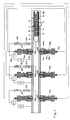
- a multi-stage travelling charge gun having a launcher tube 1 containing a projectile 2.
- Attached to the rear of the projectile 2 is a three-stage travelling charge propellant having first, second and third stages 3, 4 and 5 respectively. The three stages are consumed successively, and the first stage 3 is therefore located rearmost.
- the initiating charge 6 is not attached to the projectile 1 and may be constituted by a chemical propellant which is ignited by a conventional igniter 6a or by injecting hot gases therein so as to cause ignition at an enhanced rate of burning, in accordance with the invention.
- inertial buffer layers 7 and 8 Separating the three propellant stages are inertial buffer layers 7 and 8 respectively, which may be constituted by copper, polycarbonate or any other suitable non-combustible material. Likewise, an inertial buffer layer 9 separates the rearmost stage 3 from the initiating charge 6.
- Each of the three propellant stages 4, 5 and 6 is ignited by a corresponding injector unit 10a, 10b and 10c, respectively, positioned transversely along the tube 1, by means of which high pressure hot gas jets 12a, 12b, and 12c may be injected into the corresponding propellant charge stages.
- the construction and operation of the hot gas injector units is identical for each of the three propellant charge stages, and will therefore be described in detail with reference to the first injector unit 10a only.
- Each injector unit 10a comprises a longitudinal tubular portion 13a along an inner wall of which is situated an insulating hydrocarbon sleeve 14a (such as polyethylene). Disposed across opposite ends of the tubular portion 13a are electrodes 16a and 17a across which is connected a high voltage source 18a.
- the high voltage source 18a is adapted to be discharged across the electrodes 16a and 17a by means of a switching circuit 20a which is connected in series with a trigger circuit 22a.
- the electrode 17a is flared so as to produce nozzles for directing the flow of high pressure hot gas jets 12a.
- a working fluid 24a of water which is to be converted into the high pressure hot gas jets 12a when the switching circuit 20a is closed.
- the injector units are similar in principle to those described, for example, in U.S. Patent No. 4,590,842 referred to above, there is here provided the additional feature that the plasma jets produced by the injector units are passed through a chamber containing a working fluid, thereby lowering the temperature of the plasma jets and avoiding the risk of damage to the launcher tube.
- sensors 25a, 25b and 25c constituted, for example, by optical fibres or pressure gauges, whose outputs are connected to the trigger circuits 22a, 22b and 22c, respectively, via corresponding delay circuits 27a, 27b and 27c.
- the first hot gas jet 12a which is injected into the first stage 3 of the propellant charge, is created by means of the application of a high voltage discharge between electrodes 16a and 17a.
- the high voltage discharge causes the hydrocarbon sleeve 14a to ablate thereby creating a high pressure plasma jet as described and illustrated, for example, in U.S. Patent Nos. 4,590,842 and 4,715,261 referred to above.
- the electrode 16a acts as a seal at the end of the tubular portion 13a remote from the electrode 17a, and thereby prevents the high pressure plasma jet 12a from escaping from the injector unit 10a.
- the high pressure plasma jet is thus directed through the working fluid 24a which is thereby converted from the liquid state to a hot gaseous state at high pressure.
- the working fluid 24a is converted to a gas having a temperature of the order of 3000°C at a pressure of between 1000 and 5000 atmospheres.
- the initiating charge 6 propels the projectile 2 from the closed end of the tube 1 to the point in the tube 1 wherein the rearmost propellant stage 3 is aligned with the first injector unit 10a.
- the initiating charge 6 is constituted by a propellant medium such as is employed in conventional guns, for providing high pressure gases which impinge on the rear of the projectile 2.
- the position of the first injector unit 10a is, therefore, preferably sited at such a position that the initiation of the first propellant stage 3 is optimally timed so as to compensate for the decreasing pressure of the gases produced by the initiation charge 6.
- the operation of the system is as follows.
- the sensors 25a, 25b and 25c constitute synchronizing means which are adapted to produce signals in response to the passage of the projectile 2.
- the output of the first sensor 25a is a suitable electrical signal which is adapted to close the switching circuit 20a by means of the trigger circuit 22a after a time delay determined by the delay circuit 27a.
- the time delay must be such that the time which elapses from the moment an electrical signal is output by the trigger circuit 18a corresponds exactly to the transit time of the projectile 2 in passing from a first position corresponding to its detection by the sensor 25a, to a second position corresponding to the rearmost propellant charge 3 being aligned with the injectors 10a.
- the inertial buffer layers 7, 8 and 9 which separate the three stages of the propellant charge 3, 4, and 5 from each other and from the initiating charge 6, prevent leading stages of the propellant charge from igniting when the high pressure gas jets are injected into corresponding trailing stages, thereby ensuring that the burning process is kept under control and preventing an undesired explosion.
- the inertial buffer layer 7 ensures that only the first stage 3 of the multi-stage propellant charge is burned during the first ignition produced by the injector unit 10a.
- the projectile 2 When the first propellant stage 3 is ignited by the first injector unit 10a, the projectile 2 is thrust forward by means of both the rocket effect produced by the backward moving gaseous combustion products as well as by the high pressure of the gases which are trapped within the closed tube 1 behind the rear of the projectile 2.
- the second and third injecting units 10b and 10c, respectively, are likewise located along the closed tube 1 at suitable intervals for igniting the second and third propellant stages 4 and 5, respectively.
- the synchronizing means are provided by means of sensors adapted to detect the passage of the projectile along the tube so as to activate the respective injector unit at the correct time.
- the synchronizing means may also be pre-programmed so as to activate the sensors at predetermined times in accordance with known criteria such as the quantity of propellant in each stage of the travelling charge, the distance between successive injector units, the propellant rate of consumption, and so on.
- Fig. 1 the features of the invention have been described with particular reference to a travelling charge gun, wherein the projectile thrust arises out of a combination of the rocket effect and high pressure exerted by gases against the rear of the projectile.
- the invention may be advantageously employed even with projectiles which are propelled by conventional means, e.g. wherein the rocket effect characterising a travelling charge is absent.
- FIG. 2 there is shown schematically such an embodiment wherein a conventional breech gun 30 is provided with an initiating charge injector unit 31 in accordance with the invention.
- the gun 30 is provided with an ammunition cartridge 33 which includes a conventional chemical propellant 34.
- the injector unit 31 is fitted to the rear of the gun 30 and comprises a main cylindrical housing 36 to which are threadably coupled two end caps 37 and 38.
- a plasma injector unit 40 Located axially within the housing 36 is a plasma injector unit 40, as described above, and comprising electrodes 41 and 42 across which is connected a high voltage source 44 in series with a switching circuit 45.
- a polyethylene sleeve 47 Within an inner core of the plasma injector unit 40 is a polyethylene sleeve 47, towards the front end of which is provided a suitable working fluid 49, such as water.
- the operation of the initiating charge injector unit 31 is as follows.
- a high voltage is applied across electrodes 41 and 42 causing the polyethylene sleeve 47 to ablate. This creates a high pressure plasma jet which is directed through the working fluid 49 converting it to a high pressure, high temperature gas jet 50.
- the hot gas jet 50 interacts with the chemical propellant 34 in the gun 30 causing it to ignite and simultaneously increasing its burning rate.
- the injector units are based on the provision of a high pressure gas jet using water as the working fluid, more generally other working fluids such as alcohol or hydrocarbons may be used with similar effect.
- the injector unit 31 is external to the ammunition cartridge 33, it will be understood that it it can also be located within the ammunition cartridge 33.
- the invention has been described with particular reference to the injection into the propellant charge of hot gases derived through the interaction of a plasma jet with a working fluid medium, it will be understood that the hot gases may be constituted by the plasma jet itself, as is known in the art.
Landscapes
- Engineering & Computer Science (AREA)
- General Engineering & Computer Science (AREA)
- Chemical & Material Sciences (AREA)
- Combustion & Propulsion (AREA)
- Physics & Mathematics (AREA)
- Electromagnetism (AREA)
- Plasma & Fusion (AREA)
- Plasma Technology (AREA)
- Generation Of Surge Voltage And Current (AREA)
- Control Of Multiple Motors (AREA)
- Particle Accelerators (AREA)
Abstract
Description
- This invention relates to a method and apparatus for accelerating projectiles. In particular, it relates to an improved method and apparatus for increasing the acceleration of a projectile to hypersonic velocities.
- Known methods for accelerating projectiles generally fall into three categories: a first approach is to apply a momentum to the rear of the projectile in order to accelerate it in accordance with Newton's Second Law of Motion. Alternatively, pressure may be applied to the rear of the projectile in order to accelerate the projectile also in accordance with Newton's Second Law of Motion; and, thirdly, a projectile may be accelerated in a similar manner to a rocket in accordance with Newton's Third Law of Motion.
- From US-A-3459101 as well as from FR-A-917369, there are known methods comprising the step of injecting hot gases into a region of the launching tube in the rear of the projectile for increasing the projectile's velocity. In particular, said prior art documents describe a plurality of chambers attached along the launching tube. These prior art suggestions have not been practically proven in known gun systems since the addition of chemical propellant charges along the launching tube, and their ignition by hot gases of the previous or primary charges do not result in the desired velocity increase of the projectile, in particular, the conventional suggestions will not result in a hypervelocity gun.
- U.S. Patent No. 2,783,684 (Yoler) describes a method and means for propagating a mass within a tube, by generating a shock wave which is accelerated down the length of the tube in order to impart energy to the mass. The shock wave is created by means of an electric arc generated within the tube via high voltage electrodes. Electrodes are spaced along the length of the tube, so that the electric arcs will continuously be generated as the shock wave travels down the tube, thereby maintaining the pressure behind the solid mass. It is thus clear that Yoler's method is based on applying sufficient pressure to the rear of the mass in order to apply a constant thrusting force in accordance with the second of the three principles recited above.
- There is likewise described in U.S. Patent No. 2,790,354 (Yoler et al.) a mass accelerator employing electrical energy in order to propagate a projectile at high speed within a tube. The principle employed is identical to that of the first Yoler patent cited above, in that the electrical energy is used to create vast quantities of gas which create a shock wave towards the rear of the projectile.
- U.S. Patent No. 4,590,842 (Goldstein et al.) describes a method and apparatus for accelerating a projectile within a tube by generating a high velocity, high pressure plasma jet behind the projectile. Plasma jet streams are continuously generated along the length of the tube in synchronism with the motion of the projectile, by applying a high voltage across a suitable dielectric wall. The resulting plasma jets are directed through nozzles so as to apply momentum and pressure at the rear of the projectile, in accordance with the first two phenomena described above.
- Electrical means for accelerating projectiles by utilizing plasma jets are also disclosed in U.S. Patent No. 4,715,261 (Goldstein et al.), wherein is described a cartridge containing a plasma source for accelerating a projectile through a gun barrel bore. The principle is identical to that employed in the first Goldstein patent cited above, in that the plasma jet imparts energy to the cartridge by means of the transfer of pressure.
- Instead of using electrical means for accelerating projectiles, it is, of course, well known that chemical propellants can be used effectively to drive projectiles in a conventional gun barrel to speeds not in excess of 2 km s⁻¹. This upper limit on the projectile velocity which can be achieved efficiently, results from the inability of the chemical reaction continuously to supply the necessary increasing gas flow rate which is required for a constant thrust force at the base of the projectile.
- This limitation of chemical propellants in conventional guns may be overcome at least to some extent in the travelling charge gun. In such a gun, as well as the conventional initial charge, an additional propellant charge is attached to the rear of the projectile, and is ignited during the acceleration process. Thus, the additional propellant charge constitutes a travelling charge which travels with the projectile until it is completely consumed, the projectile being forwardly propelled by means of the backward thrust of the burning propellant charge, relative to the projectile, which creates a corresponding forward reactive thrust on the projectile. Normally, the projectile is accelerated from rest using conventional initiating means, ignition of the travelling charge only commencing after the projectile has travelled a predetermined distance, and has therefore acquired a minimum initial velocity.
- By using this technique, it is possible to obtain higher velocities due to the combined action of both the thermal pressure produced by the hot gaseous products of combustion, and a rocket mechanism which contributes additional thrust to the projectile in accordance with the third of the phenomena described above. It has been shown theoretically that in a travelling charge gun a ballistic situation can be established, in which the propellant burning rate constantly increases proportionally to the projectile velocity, so as to maintain a constant pressure in the barrel behind the projectile.
- The thermal pressure towards the rear of the projectile decreases significantly only when the velocity of the projectile exceeds approximately two and a half times the speed of sound of the propellant gases. This speed is the relative difference in the velocities of the gaseous products of combustion which accelerate the travelling charge, and the gases which expand from the breech of the gun. Thus, whilst the contribution of thermal pressure to the acceleration process is limited, higher velocities may nevertheless be achieved even when this limitation is reached, by employing a rocket mechanism which can be sustained in the barrel. In principle, therefore, the travelling charge gun provides an efficient method and apparatus for accelerating a projectile in order to achieve high velocities of several kilometers per second, i.e. beyond the limits of conventional guns.
- Nevertheless, travelling charge guns have not enjoyed widespread use, mainly owing to the difficulty of obtaining the required burning rates of the propellants, which rates have to be controlled continuously throughout the acceleration of the projectile.
- It is the object of the invention to provide a new method as well as an apparatus for increasing the velocity of the projectile of the type which is accelerated in a launching tube by a soild propellant disposed at the rear of the projectile.
- According to the present invention the combustion rate of said solid propellant is increased with the aid of plasma or hot gas jets which are generated by high current electrical discharges which are ejected in the rear of said projectile so as to interact with said solid propellant.
- According to a preferred embodiment of the inventive method a multi-stage travelling charge propellant is attached to the rear of the projectile.
- The inventive apparatus for carrying out the method of the present invention is defined by at least one injector for injecting the hot gases or plasma jets into the launcher tube in the region thereof in which said propellant is to be located.
- According to a preferred embodiment of the inventive apparatus at least one injector unit is adapted to initiate a combustion of the propellant charge.
- Generally, the invention can be applied to a launching tube constituted by a conventional gun barrel so as to apply a very high intitial thrust to the projectile, thereby to achieve higher starting accelerations than can be obtained using conventional initiation methods, whilst at the same time achieving greater control of the gas pressure within the tube.
- In the preferred embodiment of the invention, the projectile is provided with a travelling charge disposed within a suitable gun barrel, the travelling charge comprising chemical propellants which are consumed in stages as the projectile progresses down the gun barrel. The combustion of the travelling charge is in effect similar to the firing of a multi-stage rocket, except that rocket exhaust is exposed to the atmosphere, whilst the launching tube containing the projectile is closed at one end so as to provide an additonal trust on the projectile by means of the increased pressure of the trapped gases. In order to effect the ignition of each propellant stage, hot gases at high pressure are introduced into the gun barrel in the region of the travelling charge. This not only ignites the relevant propellant stage but also increases its burning rate to a much higher value than would be achieved with conventional methods of igniting chemical propellant charges.
- The invention can be applied to a travelling charge gun in this manner, in respect of a wide range of projectile sizes and can also provide an extended velocity range as compared with that obtainable with conventional propellant means. To achieve such a result, the travelling charge gun contains an initial regular chemical propellant charge in addition to a multi-stage travelling charge attached to the projectile base. It is arranged that the ignition of each subsequent stage of the travelling charge is effected when the pressure within the gun barrel falls below a predetermined threshold. In practice, such ignition is initiated slightly before the previous propellant stage has been completely consumed. In this way, the pressure profile within the gun barrel may be controlled by means of the products of combustion of the travelling charge, which tend to increase the pressure behind the projectile, thereby compensating for the increasing volume in the tube behind the projectile.
- The physical characteristics of the propellant, such as grain size, together with its chemical properties, influence the correct burning speed of the propellant and thereby maintain the desired substantially constant pressure within the gun barrel. As the projectile continues to progress along the gun barrel, the pressure falls within the gun barrel towards the rear of the projectile.
- In accordance with an aspect of the invention, there are provided injectors along the gun barrel which are initiated in synchronism with the displacement of the projectile in the tube, and thereby to the fall in gas pressure behind the projectile. Preferably, the injectors provide hot gases which create regions of high pressure and temperature within the travelling charge itself, thereby producing an increased propellant burning speed. This process is repeated along the barrel, as required, by generating further hot gas streams by means of an appropriate electrical discharge.
- In order to prevent the possibility of the propellant burning process developing into a detonative reaction, each stage of the propellant charge is preferably isolated from an adjacent stage by introducing an inertial buffer layer, which is non-combustible, thereby ensuring that only one stage of the propellant charge is burned with a single injection of gases, in accordance with the invention.
- In order to synchronize the gas injection with the displacement of the projectile within the tube, optical fibres or other sensors are located along the gun barrel facing the bore, so as to sense the passage of the projectile within the gun barrel.
- The invention will now be described by way of example and with regard to a method and apparatus for accelerating a projectile with reference to the accompanying drawings in which:
- Fig. 1 is a schematic longitudinal sectional view of a travelling charge gun with a projectile having a multi-stage propellant charge, according to a first embodiment of the invention, and
- Fig. 2 is a schematic longitudinal sectional view of a conventional gun employing an improved initiating charge in accordance with a second embodiment of the invention.
- Referring to Fig. 1, there is shown a multi-stage travelling charge gun having a launcher tube 1 containing a
projectile 2. Attached to the rear of theprojectile 2 is a three-stage travelling charge propellant having first, second andthird stages first stage 3 is therefore located rearmost. - The launcher tube 1, which is closed at one end, has located therein an initiating
charge 6 which is designed to accelerate the projectile 2 to a predetermined velocity. The initiatingcharge 6 is not attached to the projectile 1 and may be constituted by a chemical propellant which is ignited by a conventional igniter 6a or by injecting hot gases therein so as to cause ignition at an enhanced rate of burning, in accordance with the invention. - Separating the three propellant stages are
inertial buffer layers 7 and 8 respectively, which may be constituted by copper, polycarbonate or any other suitable non-combustible material. Likewise, an inertial buffer layer 9 separates therearmost stage 3 from the initiatingcharge 6. Each of the threepropellant stages corresponding injector unit hot gas jets first injector unit 10a only. - Each
injector unit 10a comprises a longitudinal tubular portion 13a along an inner wall of which is situated an insulating hydrocarbon sleeve 14a (such as polyethylene). Disposed across opposite ends of the tubular portion 13a areelectrodes electrodes switching circuit 20a which is connected in series with a trigger circuit 22a. Towards the end of eachinjector 10a adjacent to the periphery of the tube 1, theelectrode 17a is flared so as to produce nozzles for directing the flow of high pressure hot gas jets 12a. Located within eachinjector unit 10a between theelectrode 17a and the periphery of the tube 1 is a workingfluid 24a of water which is to be converted into the high pressure hot gas jets 12a when theswitching circuit 20a is closed. - Thus, although the injector units are similar in principle to those described, for example, in U.S. Patent No. 4,590,842 referred to above, there is here provided the additional feature that the plasma jets produced by the injector units are passed through a chamber containing a working fluid, thereby lowering the temperature of the plasma jets and avoiding the risk of damage to the launcher tube.
- Situated within the tube 1 are
sensors delay circuits - The first hot gas jet 12a, which is injected into the
first stage 3 of the propellant charge, is created by means of the application of a high voltage discharge betweenelectrodes electrode 16a acts as a seal at the end of the tubular portion 13a remote from theelectrode 17a, and thereby prevents the high pressure plasma jet 12a from escaping from theinjector unit 10a. The high pressure plasma jet is thus directed through the workingfluid 24a which is thereby converted from the liquid state to a hot gaseous state at high pressure. Typically, the workingfluid 24a is converted to a gas having a temperature of the order of 3000°C at a pressure of between 1000 and 5000 atmospheres. - The initiating
charge 6 propels the projectile 2 from the closed end of the tube 1 to the point in the tube 1 wherein therearmost propellant stage 3 is aligned with thefirst injector unit 10a. Normally the initiatingcharge 6 is constituted by a propellant medium such as is employed in conventional guns, for providing high pressure gases which impinge on the rear of theprojectile 2. As theprojectile 2 progresses further down the closed tube 1, so the volume behind the projectile increases and, consequently, the pressure of the gases produced by the initiatingcharge 6 will decrease. The position of thefirst injector unit 10a is, therefore, preferably sited at such a position that the initiation of thefirst propellant stage 3 is optimally timed so as to compensate for the decreasing pressure of the gases produced by theinitiation charge 6. - The operation of the system is as follows. The
sensors projectile 2. The output of thefirst sensor 25a is a suitable electrical signal which is adapted to close theswitching circuit 20a by means of the trigger circuit 22a after a time delay determined by the delay circuit 27a. The time delay must be such that the time which elapses from the moment an electrical signal is output by the trigger circuit 18a corresponds exactly to the transit time of the projectile 2 in passing from a first position corresponding to its detection by thesensor 25a, to a second position corresponding to therearmost propellant charge 3 being aligned with theinjectors 10a. - The
inertial buffer layers 7, 8 and 9 which separate the three stages of thepropellant charge charge 6, prevent leading stages of the propellant charge from igniting when the high pressure gas jets are injected into corresponding trailing stages, thereby ensuring that the burning process is kept under control and preventing an undesired explosion. Thus, for example, theinertial buffer layer 7 ensures that only thefirst stage 3 of the multi-stage propellant charge is burned during the first ignition produced by theinjector unit 10a. - When the
first propellant stage 3 is ignited by thefirst injector unit 10a, theprojectile 2 is thrust forward by means of both the rocket effect produced by the backward moving gaseous combustion products as well as by the high pressure of the gases which are trapped within the closed tube 1 behind the rear of theprojectile 2. The second andthird injecting units third propellant stages - In the described embodiment the synchronizing means are provided by means of sensors adapted to detect the passage of the projectile along the tube so as to activate the respective injector unit at the correct time. However, the synchronizing means may also be pre-programmed so as to activate the sensors at predetermined times in accordance with known criteria such as the quantity of propellant in each stage of the travelling charge, the distance between successive injector units, the propellant rate of consumption, and so on.
- In Fig. 1 the features of the invention have been described with particular reference to a travelling charge gun, wherein the projectile thrust arises out of a combination of the rocket effect and high pressure exerted by gases against the rear of the projectile. However, it will be apparent that the invention may be advantageously employed even with projectiles which are propelled by conventional means, e.g. wherein the rocket effect characterising a travelling charge is absent.
- Referring to Fig. 2 there is shown schematically such an embodiment wherein a
conventional breech gun 30 is provided with an initiatingcharge injector unit 31 in accordance with the invention. - The
gun 30 is provided with anammunition cartridge 33 which includes aconventional chemical propellant 34. Theinjector unit 31 is fitted to the rear of thegun 30 and comprises a maincylindrical housing 36 to which are threadably coupled twoend caps housing 36 is aplasma injector unit 40, as described above, and comprisingelectrodes high voltage source 44 in series with a switchingcircuit 45. Within an inner core of theplasma injector unit 40 is apolyethylene sleeve 47, towards the front end of which is provided a suitable workingfluid 49, such as water. - The operation of the initiating
charge injector unit 31 is as follows. When the switchingcircuit 45 is closed, a high voltage is applied acrosselectrodes polyethylene sleeve 47 to ablate. This creates a high pressure plasma jet which is directed through the workingfluid 49 converting it to a high pressure, hightemperature gas jet 50. Thehot gas jet 50 interacts with thechemical propellant 34 in thegun 30 causing it to ignite and simultaneously increasing its burning rate. - It has been found that the initial thrust produced by such an initiating unit is sufficiently greater than that derived in conventional guns to render the provision of such a modified initiating unit sufficiently advantageous, even without the cascaded effect of multi-stage propellant combustion provided in the first embodiment.
- It will also be understood that whilst in the preferred embodiments, the injector units are based on the provision of a high pressure gas jet using water as the working fluid, more generally other working fluids such as alcohol or hydrocarbons may be used with similar effect.
- Whilst in the preferred embodiment, the
injector unit 31 is external to theammunition cartridge 33, it will be understood that it it can also be located within theammunition cartridge 33. - Additionally, although the invention has been described with particular reference to the injection into the propellant charge of hot gases derived through the interaction of a plasma jet with a working fluid medium, it will be understood that the hot gases may be constituted by the plasma jet itself, as is known in the art.
Claims (18)
- Method for increasing the velocity of a projectile of the type which is accelerated in a launcher tube by a solid propellant disposed at the rear of the projectile,
characterized in that
the combustion rate of said solid propellant is increased with the aid of plasma or hot gas jets which are generated by high current electrical discharges which are ejected in the rear of said projectile so as to interact with said solid propellant. - A method according to Claim 1, wherein in addition to said propellant charge (6;34) there is provided a multi-stage (3,4,5) attached to the rear of said projectile (2;33).
- An apparatus for carrying out the method according to claim 1 or 2,
characterized by
at least one injector (10a,10b,10c,40) for injecting the hot gases or plasma jets into said launcher tuber in the region thereof in which said propellant is to be located. - An apparatus according to Claim 3 for accelerating said projectile from rest, wherein said at least one injector unit (40) is adapted to initiate the combustion of said propellant charge.
- An apparatus according to Claim 3 or 4, wherein said tube (30) is constituted by a conventional breech gun barrel.
- An apparatus according to any one of Claims 3 to 5, wherein said injector unit (40) includes means (47) responsive to the electrical discharge means for generating a high pressure plasma jet.
- An apparatus according to Claim 6, wherein said injector unit further includes a working fluid (49) adapted to be heated by said plasma jet, thereby producing said hot gases.
- An apparatus according to claim 3 wherein said apparatus is in the form of a travelling charge gun, and wherein the launcher tube (1) is adapted to contain a multi-stage propellant charge (3,4,5,6), characterized by at least one injector (10a,10b,10c) corresponding to a respective stage (3,4,5) of said multi-stage propellant charge for the injection of hot gases into said launcher tube (1) in the region thereof in which said respective propellant charge stage is to be burnt, and by means for synchronizing each of said injections with the alignment of successive stages of said propellant charge with the corresponding injector (10a,10b,10c).
- An apparatus according to Claim 8, wherein said synchronizing means (22a) is preprogrammed to activate each injector unit at a predetermined time.
- An apparatus according to Claim 8, wherein said synchronizing means (22a) includes a detector element (25a,25b,25c) located within the launcher tube (1).
- An apparatus according to Claim 10 and further comprising at least one delay circuit (27a,27b,27c) responsive to said signal and coupled to a respective injector (10a,10b,10c), for activating said injector after a predetermined time, corresponding to the time taken from the activation of the rearmost detector by the projectile until the corresponding propellant charge reaches the respective injector.
- An apparatus according to Claim 10 or 11, wherein the detector element (25a,25b,25c) includes a fibre-optic link.
- An apparatus according to Claim 10 or 11, wherein the detector element (25a,25b,25c) includes a pressure gauge.
- An apparatus according to any one of Claims 8 to 13, wherein each injector unit (10a,10b,10c) includes means responsive to the electrical discharge means for injecting a high pressure plasma jet.
- An apparatus according to Claim 14, wherein each injector further includes a working fluid (24a) adapted to be heated by a respective plasma jet, thereby producing the hot gases.
- An apparatus according to claim 8, wherein said projectile (2) for launching a travelling charge gun is provided with a travelling charge propellant each stage of which (3,4,5) is isolated from an adjacent stage by means of an inertial non-combustible buffer layer (7,8).
- An apparatus according to Claim 16, wherein the buffer layer (7,8) is made of copper.
- An apparatus according to Claim 16, wherein the buffer layer (7,8) is made of a polycarbonate material.
Priority Applications (1)
| Application Number | Priority Date | Filing Date | Title |
|---|---|---|---|
| AT89103594T ATE100576T1 (en) | 1988-03-03 | 1989-03-01 | METHOD AND DEVICE FOR ACCELERATING PROJECTIONS. |
Applications Claiming Priority (2)
| Application Number | Priority Date | Filing Date | Title |
|---|---|---|---|
| IL85622A IL85622A (en) | 1988-03-03 | 1988-03-03 | Method and apparatus for accelerating projectiles |
| IL85622 | 1988-03-03 |
Publications (2)
| Publication Number | Publication Date |
|---|---|
| EP0331150A1 EP0331150A1 (en) | 1989-09-06 |
| EP0331150B1 true EP0331150B1 (en) | 1994-01-19 |
Family
ID=11058640
Family Applications (1)
| Application Number | Title | Priority Date | Filing Date |
|---|---|---|---|
| EP89103594A Expired - Lifetime EP0331150B1 (en) | 1988-03-03 | 1989-03-01 | A method and apparatus for accelerating projectiles |
Country Status (7)
| Country | Link |
|---|---|
| US (1) | US5016518A (en) |
| EP (1) | EP0331150B1 (en) |
| AT (1) | ATE100576T1 (en) |
| DE (1) | DE68912362T2 (en) |
| ES (1) | ES2050170T3 (en) |
| IE (1) | IE60787B1 (en) |
| IL (1) | IL85622A (en) |
Families Citing this family (19)
| Publication number | Priority date | Publication date | Assignee | Title |
|---|---|---|---|---|
| US4895062A (en) * | 1988-04-18 | 1990-01-23 | Fmc Corporation | Combustion augmented plasma gun |
| IL89231A (en) * | 1989-02-09 | 1992-11-15 | Israel Atomic Energy Comm | Gun with combined operation by explosive material and plasma |
| US5233903A (en) * | 1989-02-09 | 1993-08-10 | The State Of Israel, Atomic Energy Commission, Soreq Nuclear Research Center | Gun with combined operation by chemical propellant and plasma |
| DE3921400C2 (en) * | 1989-06-29 | 1997-03-27 | Deutsch Franz Forsch Inst | Cannon arrangement |
| DE4003320C2 (en) * | 1990-02-05 | 1995-02-09 | Rheinmetall Gmbh | Projectile for electrothermal accelerators |
| US5612506A (en) * | 1994-10-26 | 1997-03-18 | General Dynamics Land Systems, Inc. | Method of and apparatus for generating a high pressure gas pulse using fuel and oxidizer that are relatively inert at ambient conditions |
| GB2318856B (en) * | 1996-10-30 | 2000-07-05 | Secr Defence | Means for controlling the muzzle velocity of a projectile |
| IL120140A (en) * | 1997-02-04 | 2001-01-11 | Israel Atomic Energy Comm | Thermal spray coating element and method and apparatus for using same |
| RU2162585C1 (en) * | 1999-07-15 | 2001-01-27 | Таланов Борис Петрович | Method for shot making |
| EP1371929B1 (en) * | 2002-06-12 | 2006-08-30 | Oerlikon Contraves Ag | Device for a firearm and firearm |
| DE10326610B4 (en) * | 2003-06-13 | 2011-02-24 | Deutsch-Französisches Forschungsinstitut Saint-Louis, Saint-Louis | Driving body arrangement of a projectile for a rail gun |
| US7775148B1 (en) * | 2005-01-10 | 2010-08-17 | Mcdermott Patrick P | Multivalve hypervelocity launcher (MHL) |
| US7950379B2 (en) * | 2007-07-27 | 2011-05-31 | Advanced Launch Corporation | High velocity mass accelerator and method of use thereof |
| DE102009043491A1 (en) * | 2009-09-30 | 2011-04-07 | Rheinmetall Waffe Munition Gmbh | Activation unit for ammunition-free decoys |
| US9360285B1 (en) * | 2014-07-01 | 2016-06-07 | Texas Research International, Inc. | Projectile cartridge for a hybrid capillary variable velocity electric gun |
| US10669046B2 (en) * | 2017-03-02 | 2020-06-02 | 8 Rivers Capital, Llc | Systems and methods for improving efficiency of electroantimagnetic launchers |
| WO2018236938A1 (en) * | 2017-06-19 | 2018-12-27 | EnergeticX.net, L.L.C. | Systems and techniques for launching a payload |
| US11846486B2 (en) * | 2020-09-25 | 2023-12-19 | Modern Pneumatic Sporting Devices Llc | Pneumatic sequential injection rifle |
| CN112797844A (en) * | 2021-02-07 | 2021-05-14 | 中国科学技术大学 | Spiral gunpowder accelerator |
Family Cites Families (11)
| Publication number | Priority date | Publication date | Assignee | Title |
|---|---|---|---|---|
| US1349414A (en) * | 1915-06-19 | 1920-08-10 | Dougan Kennedy | Submarine gun |
| US1248785A (en) * | 1917-10-04 | 1917-12-04 | Om Edwards Co Inc | Window-sash and holder. |
| FR917369A (en) * | 1945-11-14 | 1947-01-06 | Special device for launching firearm projectiles | |
| DE1056968B (en) * | 1955-08-19 | 1959-05-06 | Boelkow Entwicklungen Kg | Barrel with several propellants distributed over the length of the barrel |
| US3459101A (en) * | 1967-11-09 | 1969-08-05 | Us Army | High velocity weapon |
| US3495349A (en) * | 1967-12-26 | 1970-02-17 | Moore Alvin E | Electrically-fired gun having a vertically movable missile transferring and firing chamber means |
| CA904697A (en) * | 1968-09-25 | 1972-07-11 | Her Majesty The Queen In Right Of Canada As Represented By The Minister Of National Defence Of Her Majesty's Canadian Government | Switch for projectile accelerating system |
| US3736839A (en) * | 1972-02-24 | 1973-06-05 | Us Navy | Dual mode shotgun |
| US4590842A (en) * | 1983-03-01 | 1986-05-27 | Gt-Devices | Method of and apparatus for accelerating a projectile |
| US4640180A (en) * | 1985-06-20 | 1987-02-03 | The United States Of America As Represented By The Secretary Of The Navy | Gun-firing system |
| US4711154A (en) * | 1985-10-31 | 1987-12-08 | Fmc Corporation | Combustion augmented plasma pressure amplifier |
-
1988
- 1988-03-03 IL IL85622A patent/IL85622A/en not_active IP Right Cessation
-
1989
- 1989-02-15 IE IE48789A patent/IE60787B1/en not_active IP Right Cessation
- 1989-03-01 ES ES89103594T patent/ES2050170T3/en not_active Expired - Lifetime
- 1989-03-01 AT AT89103594T patent/ATE100576T1/en not_active IP Right Cessation
- 1989-03-01 EP EP89103594A patent/EP0331150B1/en not_active Expired - Lifetime
- 1989-03-01 DE DE89103594T patent/DE68912362T2/en not_active Expired - Fee Related
-
1990
- 1990-03-21 US US07/496,806 patent/US5016518A/en not_active Expired - Fee Related
Also Published As
| Publication number | Publication date |
|---|---|
| DE68912362T2 (en) | 1994-05-11 |
| IL85622A (en) | 1992-08-18 |
| ATE100576T1 (en) | 1994-02-15 |
| EP0331150A1 (en) | 1989-09-06 |
| IL85622A0 (en) | 1988-08-31 |
| IE60787B1 (en) | 1994-08-10 |
| US5016518A (en) | 1991-05-21 |
| ES2050170T3 (en) | 1994-05-16 |
| DE68912362D1 (en) | 1994-03-03 |
| IE890487L (en) | 1989-09-03 |
Similar Documents
| Publication | Publication Date | Title |
|---|---|---|
| EP0331150B1 (en) | A method and apparatus for accelerating projectiles | |
| CA1290178C (en) | Armament system | |
| US5233903A (en) | Gun with combined operation by chemical propellant and plasma | |
| US6138395A (en) | Barrel assembly with axially stacked projectiles | |
| US5578783A (en) | RAM accelerator system and device | |
| US4938112A (en) | Apparatus and method for the acceleration of projectiles to hypervelocities | |
| US3253511A (en) | Launching process and apparatus | |
| US5355764A (en) | Plasma actuated ignition and distribution pump | |
| US4726279A (en) | Wake stabilized supersonic combustion ram cannon | |
| US5097743A (en) | Method and apparatus for zero velocity start ram acceleration | |
| US4722261A (en) | Extendable ram cannon | |
| US4930421A (en) | Partitioned, fluid supported, high efficiency traveling charge for hyper-velocity guns | |
| GB2183800A (en) | Recoilless firing device | |
| US5171932A (en) | Electrothermal chemical propulsion apparatus and method for propelling a projectile | |
| US5322002A (en) | Tube launched weapon system | |
| US3388633A (en) | Multi-staged ballistic device | |
| US3418878A (en) | Method and means for augmenting hypervelocity flight | |
| EP0382000B1 (en) | A gun with combined operation by chemical propellant and plasma | |
| JPH024197A (en) | Gun device using liquefied gunpowder | |
| RU2689056C1 (en) | Method and device for gas-dynamic acceleration of massive bodies to high speed | |
| US5121670A (en) | Ram accelerator | |
| RU2812284C1 (en) | Method of firing shot from ballistic installation using cumulative and hydrodynamic effect | |
| Higgins et al. | Gasdynamic operation of baffled tube ram accelerator in highly energetic mixtures | |
| USH927H (en) | Post burn hydrogen light gas cartridge | |
| USH684H (en) | Vented in-tube burning rocket |
Legal Events
| Date | Code | Title | Description |
|---|---|---|---|
| PUAI | Public reference made under article 153(3) epc to a published international application that has entered the european phase |
Free format text: ORIGINAL CODE: 0009012 |
|
| AK | Designated contracting states |
Kind code of ref document: A1 Designated state(s): AT BE CH DE ES FR GB GR IT LI LU NL SE |
|
| 17P | Request for examination filed |
Effective date: 19900207 |
|
| 17Q | First examination report despatched |
Effective date: 19910725 |
|
| GRAA | (expected) grant |
Free format text: ORIGINAL CODE: 0009210 |
|
| AK | Designated contracting states |
Kind code of ref document: B1 Designated state(s): AT BE CH DE ES FR GB GR IT LI LU NL SE |
|
| REF | Corresponds to: |
Ref document number: 100576 Country of ref document: AT Date of ref document: 19940215 Kind code of ref document: T |
|
| REF | Corresponds to: |
Ref document number: 68912362 Country of ref document: DE Date of ref document: 19940303 |
|
| ITF | It: translation for a ep patent filed | ||
| EPTA | Lu: last paid annual fee | ||
| REG | Reference to a national code |
Ref country code: ES Ref legal event code: FG2A Ref document number: 2050170 Country of ref document: ES Kind code of ref document: T3 |
|
| ET | Fr: translation filed | ||
| REG | Reference to a national code |
Ref country code: GR Ref legal event code: FG4A Free format text: 3011147 |
|
| PLBE | No opposition filed within time limit |
Free format text: ORIGINAL CODE: 0009261 |
|
| STAA | Information on the status of an ep patent application or granted ep patent |
Free format text: STATUS: NO OPPOSITION FILED WITHIN TIME LIMIT |
|
| 26N | No opposition filed | ||
| EAL | Se: european patent in force in sweden |
Ref document number: 89103594.1 |
|
| PGFP | Annual fee paid to national office [announced via postgrant information from national office to epo] |
Ref country code: GB Payment date: 19970220 Year of fee payment: 9 |
|
| PGFP | Annual fee paid to national office [announced via postgrant information from national office to epo] |
Ref country code: DE Payment date: 19970307 Year of fee payment: 9 |
|
| PGFP | Annual fee paid to national office [announced via postgrant information from national office to epo] |
Ref country code: CH Payment date: 19970311 Year of fee payment: 9 |
|
| PGFP | Annual fee paid to national office [announced via postgrant information from national office to epo] |
Ref country code: FR Payment date: 19970313 Year of fee payment: 9 Ref country code: AT Payment date: 19970313 Year of fee payment: 9 |
|
| PGFP | Annual fee paid to national office [announced via postgrant information from national office to epo] |
Ref country code: SE Payment date: 19970319 Year of fee payment: 9 |
|
| PGFP | Annual fee paid to national office [announced via postgrant information from national office to epo] |
Ref country code: GR Payment date: 19970321 Year of fee payment: 9 |
|
| PGFP | Annual fee paid to national office [announced via postgrant information from national office to epo] |
Ref country code: ES Payment date: 19970324 Year of fee payment: 9 |
|
| PGFP | Annual fee paid to national office [announced via postgrant information from national office to epo] |
Ref country code: NL Payment date: 19970327 Year of fee payment: 9 |
|
| PGFP | Annual fee paid to national office [announced via postgrant information from national office to epo] |
Ref country code: LU Payment date: 19970407 Year of fee payment: 9 |
|
| PGFP | Annual fee paid to national office [announced via postgrant information from national office to epo] |
Ref country code: BE Payment date: 19970521 Year of fee payment: 9 |
|
| PG25 | Lapsed in a contracting state [announced via postgrant information from national office to epo] |
Ref country code: LU Free format text: LAPSE BECAUSE OF NON-PAYMENT OF DUE FEES Effective date: 19980301 Ref country code: GB Free format text: LAPSE BECAUSE OF NON-PAYMENT OF DUE FEES Effective date: 19980301 Ref country code: AT Free format text: LAPSE BECAUSE OF NON-PAYMENT OF DUE FEES Effective date: 19980301 |
|
| PG25 | Lapsed in a contracting state [announced via postgrant information from national office to epo] |
Ref country code: SE Free format text: LAPSE BECAUSE OF NON-PAYMENT OF DUE FEES Effective date: 19980302 Ref country code: ES Free format text: LAPSE BECAUSE OF NON-PAYMENT OF DUE FEES Effective date: 19980302 |
|
| PG25 | Lapsed in a contracting state [announced via postgrant information from national office to epo] |
Ref country code: LI Free format text: LAPSE BECAUSE OF NON-PAYMENT OF DUE FEES Effective date: 19980331 Ref country code: GR Free format text: LAPSE BECAUSE OF NON-PAYMENT OF DUE FEES Effective date: 19980331 Ref country code: FR Free format text: THE PATENT HAS BEEN ANNULLED BY A DECISION OF A NATIONAL AUTHORITY Effective date: 19980331 Ref country code: CH Free format text: LAPSE BECAUSE OF NON-PAYMENT OF DUE FEES Effective date: 19980331 Ref country code: BE Free format text: LAPSE BECAUSE OF NON-PAYMENT OF DUE FEES Effective date: 19980331 |
|
| BERE | Be: lapsed |
Owner name: THE STATE OF ISRAEL ATOMIC ENERGY COMMISSION SORE Effective date: 19980331 |
|
| PG25 | Lapsed in a contracting state [announced via postgrant information from national office to epo] |
Ref country code: NL Free format text: LAPSE BECAUSE OF NON-PAYMENT OF DUE FEES Effective date: 19981001 |
|
| GBPC | Gb: european patent ceased through non-payment of renewal fee |
Effective date: 19980301 |
|
| REG | Reference to a national code |
Ref country code: CH Ref legal event code: PL |
|
| NLV4 | Nl: lapsed or anulled due to non-payment of the annual fee |
Effective date: 19981001 |
|
| PG25 | Lapsed in a contracting state [announced via postgrant information from national office to epo] |
Ref country code: DE Free format text: LAPSE BECAUSE OF NON-PAYMENT OF DUE FEES Effective date: 19981201 |
|
| EUG | Se: european patent has lapsed |
Ref document number: 89103594.1 |
|
| REG | Reference to a national code |
Ref country code: FR Ref legal event code: ST |
|
| REG | Reference to a national code |
Ref country code: ES Ref legal event code: FD2A Effective date: 20000403 |
|
| PG25 | Lapsed in a contracting state [announced via postgrant information from national office to epo] |
Ref country code: IT Free format text: LAPSE BECAUSE OF NON-PAYMENT OF DUE FEES;WARNING: LAPSES OF ITALIAN PATENTS WITH EFFECTIVE DATE BEFORE 2007 MAY HAVE OCCURRED AT ANY TIME BEFORE 2007. THE CORRECT EFFECTIVE DATE MAY BE DIFFERENT FROM THE ONE RECORDED. Effective date: 20050301 |