EP0331109A2 - Vorrichtung zur Regelung eines Flüssigkeitsniveaus - Google Patents
Vorrichtung zur Regelung eines Flüssigkeitsniveaus Download PDFInfo
- Publication number
- EP0331109A2 EP0331109A2 EP89103501A EP89103501A EP0331109A2 EP 0331109 A2 EP0331109 A2 EP 0331109A2 EP 89103501 A EP89103501 A EP 89103501A EP 89103501 A EP89103501 A EP 89103501A EP 0331109 A2 EP0331109 A2 EP 0331109A2
- Authority
- EP
- European Patent Office
- Prior art keywords
- float body
- liquid
- level
- liquid level
- ballast
- Prior art date
- Legal status (The legal status is an assumption and is not a legal conclusion. Google has not performed a legal analysis and makes no representation as to the accuracy of the status listed.)
- Withdrawn
Links
Images
Classifications
-
- G—PHYSICS
- G05—CONTROLLING; REGULATING
- G05D—SYSTEMS FOR CONTROLLING OR REGULATING NON-ELECTRIC VARIABLES
- G05D9/00—Level control, e.g. controlling quantity of material stored in vessel
- G05D9/12—Level control, e.g. controlling quantity of material stored in vessel characterised by the use of electric means
-
- H—ELECTRICITY
- H01—ELECTRIC ELEMENTS
- H01H—ELECTRIC SWITCHES; RELAYS; SELECTORS; EMERGENCY PROTECTIVE DEVICES
- H01H35/00—Switches operated by change of a physical condition
- H01H35/18—Switches operated by change of liquid level or of liquid density, e.g. float switch
- H01H35/186—Switches operated by change of liquid level or of liquid density, e.g. float switch making use of a cable suspended floater containing an inclination sensing switch
-
- Y—GENERAL TAGGING OF NEW TECHNOLOGICAL DEVELOPMENTS; GENERAL TAGGING OF CROSS-SECTIONAL TECHNOLOGIES SPANNING OVER SEVERAL SECTIONS OF THE IPC; TECHNICAL SUBJECTS COVERED BY FORMER USPC CROSS-REFERENCE ART COLLECTIONS [XRACs] AND DIGESTS
- Y10—TECHNICAL SUBJECTS COVERED BY FORMER USPC
- Y10T—TECHNICAL SUBJECTS COVERED BY FORMER US CLASSIFICATION
- Y10T137/00—Fluid handling
- Y10T137/0318—Processes
- Y10T137/0324—With control of flow by a condition or characteristic of a fluid
-
- Y—GENERAL TAGGING OF NEW TECHNOLOGICAL DEVELOPMENTS; GENERAL TAGGING OF CROSS-SECTIONAL TECHNOLOGIES SPANNING OVER SEVERAL SECTIONS OF THE IPC; TECHNICAL SUBJECTS COVERED BY FORMER USPC CROSS-REFERENCE ART COLLECTIONS [XRACs] AND DIGESTS
- Y10—TECHNICAL SUBJECTS COVERED BY FORMER USPC
- Y10T—TECHNICAL SUBJECTS COVERED BY FORMER US CLASSIFICATION
- Y10T137/00—Fluid handling
- Y10T137/7287—Liquid level responsive or maintaining systems
Definitions
- This invention relates to a liquid level regulator device of the kind used to control the level of a liquid such as water in a storage tank, sump or other type of container.
- a liquid level regulator device which comprises a tear drop shaped plastic body which is selectively weighted according to the specific gravity of the liquid in which it is to be used.
- the above device is used in pairs, and two regulator devices are in use suspended from electrical cables which are supported vertically above the tank or container for the liquid. The devices are hung at different heights, corresponding to desired maximum and minimum liquid levels. When each device is free of the liquid, it hangs vertically. When the liquid level rises sufficiently to substantially submerge the device, it tilts, actuating an attitude sensitive switch within the housing of the device. The switching action is used to actuate a pump controller or other liquid level control device. Using this arrangement, a pump may be activated to fill the container when the liquid level drops to a predetermined minimum level and the pump may be deactivated when the level reaches a predetermined maximum level.
- the known device does not float in the water, but is arranged so that its base portion is more buoyant than its neck portion, which causes a tilting action of the device when submerged.
- the effect of this arrangement is that the switching action of the device is rather sluggish, and a positive switching action may not be obtained, particularly when there is a degree of turbulence in the liquid.
- a disadvantage of the above arrangement is that the regulator device, when in the process of being submerged, reaches an intermediate stage between the vertical on the one hand and fully tilted on the other hand wherein the switching mechanisms within the device tends to open and close a few times intermittently. This is highly undesirable since this causes the pump motor to be switched on and off and can accordingly cause damage to the motor. This situation is usually aggravated where the devices are used in industrial or mining applications where the liquid in the tank remains turbulent.
- a liquid level regulator device comprising: a float body; an elongate flexible anchor means attached to a first end of said float body and attachable to an anchor point within a vessel in which a liquid level is to be regulated for anchoring said float body in an orientation with one end of said float body uppermost in said liquid; a movable ballast within said float body, said ballast being movable between first and second positions near said ends of said float body for tumbling said float body for reversing said orientation in response to tilting said float body by tension on said anchor means produced by changing said liquid level; an attitude sensitive switch within said float body and responsive to said reversing of said orientation of said float body for controlling a level of said liquid.
- Another aspect of the invention includes a method of regulating a liquid level in a vessel comprising: providing a float body having a first end of an elongate flexible anchor means attached to a first end of said float body, a movable ballast within said float body and an attitude sensitive switch within said float body; attaching a second end of said anchor to a wall of said vessel at a point between a highest and a lowest level of said liquid, said float body being orientated in said liquid with one end being uppermost in said liquid; changing a level of said liquid; tensioning said anchor means for tumbling said body; moving said ballast from a first to a second position near opposite ends of said float body for reversing said orientation; reversing a state of said attitude sensitive switch for controlling a level of said liquid.
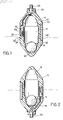
- the regulator device comprises a hollow plastics float body 10, which has a cylindrical center portion and frustoconical end portions. Internally, the body defines a cylindrical chamber 12 in which a ballast in the form of a relatively heavy steel ball 14 can move freely. At each end of the chamber 12 are roughly hemispherical sockets 16 and 18, the edges of which are defined by respective inwardly extending annular ridges 20 and 22. The inner diameter of the ridges 20 and 22 is slightly greater than the diameter of the ball 14. The ridges are coaxial with the central portion of the body.
- the bush 24 is of the type which includes a sealing gland, and serves to connect an electrical cable 26 in a liquidimpervious manner to the body 10.
- An attitude-sensitive switch 28 is supported in the wall of the body 10, and has three terminals 30, 32 and 34, to which are connected respective conductors of the cable 26.
- the switch 28 is effectively a single-pole double-throw switch, and contains an amount of mercury 36 which either bridges the terminals 32 and 34, or the terminals 30 and 34, depending on the orientation of the body 10.
- a counterweight 38 conveniently of lead or another relatively heavy metal, is fitted to the wall of the body 10 on the opposite side thereof from the switch 28.
- the shape of the annular ridges 20 and 22 is significant in determining the operating characteristics of the device.
- the ball 14 When the ball 14 is received in either of the sockets 16 and 18, it is effectively cradled by the ridge 20 or 22, and cannot easily roll out of the socket. It is thus necessary that the body 10 be tilted substantially from the vertical before the ball will leave the socket in which it is received. This is important in providing a positive switching action, as will be described below.
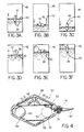
- Figure 3a shows the device of the invention floating in a container 42 of liquid such as water.
- the electrical cable 26 is fastened to an anchor 40 at one side of the container.
- the length of the electrical cable 26 is one half of the distance between the maximum and minimum permitted liquid levels in the container, and the anchor 40 is sited midway between these two levels.
- the mercury 36 in the switch 28 moves to the opposite end of the switch, opening the contacts 32 and 34, and closing the contacts 30 and 34.
- the operation of these contacts is used to control a pump, valve or other liquid level control apparatus, in a conventional manner, to cause liquid to be pumped into the container.
- the anchorage 40 is illustrated schematically, it will be appreciated that it is important to fix the cable 26 to the side of the container in such a manner as to prevent unnecessary wear thereof.
- the cable may be passed through a flared gland which accommodates a wide range of angular movement of the cable.
- the cable can be fixed to a pivoting support.
- a liquid level regulator device 50 comprises a buoyant, plastics float body 52, a movable ballast in the form of a metallic ball 54 movably located in an elongate, essentially cylindrical chamber 56, a mercury attitude sensitive switch 58 and an elongate flexible anchor member in the form of an electrical cable 60 connected at its one end to the mercury switch 58.
- Chamber 56 further includes two constricted retaining sockets 62 and 64 at its respective ends.
- Mercury switch 58 comprises an angled, metal clad or glass tubular body 66 mounted to float body 52 by means of bracket 68, with two electrodes 70 and 72 extending into tubular body 66 at opposite ends thereof. A quantity of mercury 74 is held inside tube 66.
- the tubular body is preferably angled at substantially 90°.
- the leads of cable 60 are connected to electrodes 70 and 72 and to tubular body 66 (i.e., the earth terminal) for metal-clad switches.
- tubular body 66 i.e., the earth terminal
- the common lead is connected to the common terminal of the switch.
- a molded plastics sealing gland 76 provides a watertight seal around cable 60 where it enters float body 52 through aperture 78.
- heavy ball 54 is movable within chamber 56 between the two constricted retaining sockets 62 and 64 across the length of chamber 56.
- the solid line indicates ball 54 located in socket 62 and the broken line indicates ball 54 located in socket 64.
- the inner dimensions of retaining sockets 62 and 64 are designed to retain the ball 54 stable in its associated socket until the device 50 reaches an angle of at least 80° from the vertical, whereafter ball 54 rolls across the length of the chamber 56 to the opposite retaining socket, thus providing the positive tumbling action of device 50. It will be noted that as soon as ball 12 leaves its associated socket, its velocity increases due to the effect of gravity as it enters the wider bore of chamber 56 and it gains enough momentum to carry itself into the opposite retaining socket.
- a buoyant float may be attached to the cable a small distance from the float body. This may be useful in very large tanks where the weight of the cable may be sufficient to tilt the device before the required maximum liquid level is attained or where the density of the liquid is too low to support the weight of the device and cable.
- Other possible variations include the provision of magnets to retain the ballast at the end of the chamber until the predetermined tilting angle is reached.
- any other type of attitude sensitive switch may be used, such as a mechanical gravity sensitive switch. The switch may be activated by the moving ballast itself. It should also be noted that the mercury switch shown in Figure 1, having a straight tubular body may be utilized in the embodiment of Figure 4.
Landscapes
- Physics & Mathematics (AREA)
- General Physics & Mathematics (AREA)
- Engineering & Computer Science (AREA)
- Automation & Control Theory (AREA)
- Level Indicators Using A Float (AREA)
Applications Claiming Priority (3)
| Application Number | Priority Date | Filing Date | Title |
|---|---|---|---|
| ZA881422 | 1988-02-29 | ||
| ZA881422 | 1988-02-29 | ||
| US314488 | 1989-02-28 |
Publications (2)
| Publication Number | Publication Date |
|---|---|
| EP0331109A2 true EP0331109A2 (de) | 1989-09-06 |
| EP0331109A3 EP0331109A3 (de) | 1990-10-03 |
Family
ID=25579183
Family Applications (1)
| Application Number | Title | Priority Date | Filing Date |
|---|---|---|---|
| EP19890103501 Withdrawn EP0331109A3 (de) | 1988-02-29 | 1989-02-28 | Vorrichtung zur Regelung eines Flüssigkeitsniveaus |
Country Status (2)
| Country | Link |
|---|---|
| US (1) | US4917135A (de) |
| EP (1) | EP0331109A3 (de) |
Cited By (1)
| Publication number | Priority date | Publication date | Assignee | Title |
|---|---|---|---|---|
| GR910100436A (el) * | 1991-10-23 | 1993-06-30 | Stayros Lalizas | Συσκευη αυτοματου ελεγχου της σταθμης υγρων. |
Families Citing this family (14)
| Publication number | Priority date | Publication date | Assignee | Title |
|---|---|---|---|---|
| US5089676A (en) * | 1989-05-16 | 1992-02-18 | Magnetrol International Incorporated | Liquid level float switch |
| US5087801A (en) * | 1990-06-19 | 1992-02-11 | S.J. Electro Systems, Inc. | Sphere-actuated float switch |
| US5297939A (en) * | 1993-02-01 | 1994-03-29 | Johnson Pumps Of America, Inc. | Automatic control for bilge & sump pump |
| US5562423A (en) * | 1994-10-17 | 1996-10-08 | Johnson Pumps Of America, Inc. | Automatic float control switch for a bilge and sump pump |
| US5622477A (en) * | 1995-08-15 | 1997-04-22 | Johnson Pumps Of America, Inc. | Switch for bilge and sump/pump with automatic float control |
| US7569136B2 (en) | 1997-06-24 | 2009-08-04 | Ackerson Michael D | Control system method and apparatus for two phase hydroprocessing |
| US6313417B1 (en) * | 2000-10-04 | 2001-11-06 | Honeywell International Inc. | Conducting liquid tilt switch using weighted ball |
| US6464465B2 (en) * | 2001-02-14 | 2002-10-15 | Glenn P. House | Level control device for a wastewater collection basin |
| US7748965B2 (en) | 2005-10-17 | 2010-07-06 | Itt Manufacturing Enterprises, Inc. | Livewell/baitwell pump featuring rotating transom pickup tube |
| US7409860B2 (en) * | 2006-02-14 | 2008-08-12 | Ti Group Automotive Systems, L.L.C. | Fuel level measurement device |
| KR200457249Y1 (ko) | 2008-12-17 | 2011-12-09 | 이규현 | 플롯트 센서 |
| US12421459B2 (en) | 2011-01-19 | 2025-09-23 | Duke Technologies, Llc | Process for hydroprocessing of non-petroleum feedstocks with hydrogen production |
| US9096804B2 (en) | 2011-01-19 | 2015-08-04 | P.D. Technology Development, Llc | Process for hydroprocessing of non-petroleum feedstocks |
| CN105244225B (zh) * | 2015-10-15 | 2018-01-02 | 珠海格力电器股份有限公司 | 一种液位开关及空调 |
Family Cites Families (23)
| Publication number | Priority date | Publication date | Assignee | Title |
|---|---|---|---|---|
| US1855581A (en) * | 1930-08-22 | 1932-04-26 | Arthur F Meade | Safety switch |
| US2588667A (en) * | 1949-09-10 | 1952-03-11 | Honeywell Regulator Co | Float operated control |
| US2600659A (en) * | 1949-11-10 | 1952-06-17 | Jr Charles J Koch | Combined float and mercury switch |
| DE1273216B (de) * | 1964-01-29 | 1968-07-18 | Mauno Kari | Schwimmer fuer Fluessigkeitsniveauregelung |
| DE1967781U (de) * | 1965-08-13 | 1967-09-07 | Guenter Reichensperger | Schwimmschalter fuer pumpenanlagen od. dgl. |
| DE1540333B2 (de) * | 1965-08-13 | 1971-09-30 | Reichensperger, Gunter, 4811 Olden trup | Schwimmschalter fuer pumpenanlagen oder dergleichen |
| US3393283A (en) * | 1966-03-29 | 1968-07-16 | Inreco Ab | Liquid level switch with a two-piece float body of flexible material with a two-piece rigid liner member |
| US3440375A (en) * | 1966-09-09 | 1969-04-22 | James P Wood | Float-type mercury switch with stabilizing means |
| CH482284A (de) * | 1967-10-27 | 1969-11-30 | Infanger Ernst | Schwimmerschalter |
| US3746035A (en) * | 1971-03-24 | 1973-07-17 | E Singer | Float level control apparatus |
| US3944770A (en) * | 1974-08-19 | 1976-03-16 | Genova, Inc. | Switch assembly |
| US4086457A (en) * | 1976-12-16 | 1978-04-25 | Niedermeyer Karl O | Float switch signalling two different liquid levels |
| US4171186A (en) * | 1977-08-12 | 1979-10-16 | Hydronix, Inc. | Submerged pump control |
| DE2843484C3 (de) * | 1978-10-05 | 1981-06-19 | Hermann Ruf Gmbh & Co Kg, 6800 Mannheim | Lageschalter, insbesondere Schwimmschalter |
| US4262216A (en) * | 1979-05-02 | 1981-04-14 | S. J. Electro Systems, Inc. | Float switch |
| US4302641A (en) * | 1980-05-12 | 1981-11-24 | S. J. Electro Systems, Inc. | Float switches with wide differential |
| US4399338A (en) * | 1981-09-22 | 1983-08-16 | Ocean Research Industries Of North America | Automatic float switch |
| US4373155A (en) * | 1981-11-12 | 1983-02-08 | Amp Incorporated | Brake fluid level indicator |
| FR2528996A1 (fr) * | 1982-06-21 | 1983-12-23 | Gensollen Michel | Detecteur de niveau d'un liquide a flotteur basculant |
| US4540891A (en) * | 1983-11-02 | 1985-09-10 | R. W. Beckett Corporation | High current float switch |
| US4575597A (en) * | 1984-08-03 | 1986-03-11 | The Scott & Fetzer Company | Float switch assembly having mercury-type switch movably retained within a cage |
| US4629841A (en) * | 1984-09-24 | 1986-12-16 | Expert Corporation | Attitude controlled float switch |
| US4644117A (en) * | 1985-09-26 | 1987-02-17 | Grimes Richard V | Float switch assembly |
-
1989
- 1989-02-23 US US07/314,488 patent/US4917135A/en not_active Expired - Fee Related
- 1989-02-28 EP EP19890103501 patent/EP0331109A3/de not_active Withdrawn
Cited By (1)
| Publication number | Priority date | Publication date | Assignee | Title |
|---|---|---|---|---|
| GR910100436A (el) * | 1991-10-23 | 1993-06-30 | Stayros Lalizas | Συσκευη αυτοματου ελεγχου της σταθμης υγρων. |
Also Published As
| Publication number | Publication date |
|---|---|
| EP0331109A3 (de) | 1990-10-03 |
| US4917135A (en) | 1990-04-17 |
Similar Documents
| Publication | Publication Date | Title |
|---|---|---|
| US4917135A (en) | Liquid level regulator device | |
| US4086457A (en) | Float switch signalling two different liquid levels | |
| US4262216A (en) | Float switch | |
| US20070205907A1 (en) | Switch assembly and system for high-level monitoring | |
| US5017748A (en) | Float switch with buoyant housing and switch operating means within the housing | |
| US4629841A (en) | Attitude controlled float switch | |
| US5552774A (en) | Magnetically activated float switch | |
| US4399338A (en) | Automatic float switch | |
| US4157627A (en) | Fishing line float with electric flashlight | |
| CA1310885C (en) | Liquid level regulator device | |
| US4631375A (en) | Delayed action liquid level sensing apparatus | |
| US5089676A (en) | Liquid level float switch | |
| US4329550A (en) | Delayed action liquid level sensing apparatus | |
| US6864445B1 (en) | Latching fluid level switch | |
| US3662131A (en) | Electrical liquid level sensor | |
| US4302641A (en) | Float switches with wide differential | |
| US4669990A (en) | Signal device | |
| US3792331A (en) | Interface gaging system for underwater oil storage tanks | |
| US4467156A (en) | Liquid level sensor switch | |
| US4942274A (en) | Ball controlled float control unit | |
| US3864538A (en) | Float type liquid level switch | |
| US4549171A (en) | Floating oil leak detector | |
| US3592981A (en) | Float switch apparatus | |
| US3978301A (en) | Mercury tilt switch | |
| US3183323A (en) | Submerged float switch with means to mutually adjust the metacenter and center of gravity |
Legal Events
| Date | Code | Title | Description |
|---|---|---|---|
| PUAI | Public reference made under article 153(3) epc to a published international application that has entered the european phase |
Free format text: ORIGINAL CODE: 0009012 |
|
| AK | Designated contracting states |
Kind code of ref document: A2 Designated state(s): AT BE CH DE ES FR GB GR IT LI LU NL SE |
|
| PUAL | Search report despatched |
Free format text: ORIGINAL CODE: 0009013 |
|
| AK | Designated contracting states |
Kind code of ref document: A3 Designated state(s): AT BE CH DE ES FR GB GR IT LI LU NL SE |
|
| STAA | Information on the status of an ep patent application or granted ep patent |
Free format text: STATUS: THE APPLICATION IS DEEMED TO BE WITHDRAWN |
|
| 18D | Application deemed to be withdrawn |
Effective date: 19910404 |