EP0330814A2 - Locking system for an aircraft door - Google Patents
Locking system for an aircraft door Download PDFInfo
- Publication number
- EP0330814A2 EP0330814A2 EP89100373A EP89100373A EP0330814A2 EP 0330814 A2 EP0330814 A2 EP 0330814A2 EP 89100373 A EP89100373 A EP 89100373A EP 89100373 A EP89100373 A EP 89100373A EP 0330814 A2 EP0330814 A2 EP 0330814A2
- Authority
- EP
- European Patent Office
- Prior art keywords
- lever
- door
- locking
- emergency slide
- operating
- Prior art date
- Legal status (The legal status is an assumption and is not a legal conclusion. Google has not performed a legal analysis and makes no representation as to the accuracy of the status listed.)
- Granted
Links
- 230000000903 blocking effect Effects 0.000 claims description 14
- 230000002950 deficient Effects 0.000 description 3
- 210000000629 knee joint Anatomy 0.000 description 3
- 230000006835 compression Effects 0.000 description 2
- 238000007906 compression Methods 0.000 description 2
- 238000000034 method Methods 0.000 description 2
- 238000010276 construction Methods 0.000 description 1
- 238000011161 development Methods 0.000 description 1
- 230000018109 developmental process Effects 0.000 description 1
- 230000000694 effects Effects 0.000 description 1
- 238000009434 installation Methods 0.000 description 1
- 210000002414 leg Anatomy 0.000 description 1
- 238000004519 manufacturing process Methods 0.000 description 1
- 230000000246 remedial effect Effects 0.000 description 1
- 239000000725 suspension Substances 0.000 description 1
- 238000009423 ventilation Methods 0.000 description 1
Images


Classifications
-
- B—PERFORMING OPERATIONS; TRANSPORTING
- B64—AIRCRAFT; AVIATION; COSMONAUTICS
- B64C—AEROPLANES; HELICOPTERS
- B64C1/00—Fuselages; Constructional features common to fuselages, wings, stabilising surfaces or the like
- B64C1/14—Windows; Doors; Hatch covers or access panels; Surrounding frame structures; Canopies; Windscreens accessories therefor, e.g. pressure sensors, water deflectors, hinges, seals, handles, latches, windscreen wipers
- B64C1/1407—Doors; surrounding frames
- B64C1/1423—Passenger doors
-
- B—PERFORMING OPERATIONS; TRANSPORTING
- B64—AIRCRAFT; AVIATION; COSMONAUTICS
- B64C—AEROPLANES; HELICOPTERS
- B64C1/00—Fuselages; Constructional features common to fuselages, wings, stabilising surfaces or the like
- B64C1/14—Windows; Doors; Hatch covers or access panels; Surrounding frame structures; Canopies; Windscreens accessories therefor, e.g. pressure sensors, water deflectors, hinges, seals, handles, latches, windscreen wipers
- B64C1/1407—Doors; surrounding frames
Definitions
- the invention relates to a lock according to the preamble of claim 1.
- Aircraft doors are subject to strict safety regulations to avoid accidents caused by unlocked aircraft doors.
- the latest recommendations and guidelines for the construction of aircraft doors subject to internal pressure require that appropriate precautions be taken to check that they are fully and securely locked.
- a conceivable precaution of this type can consist, for example, in that a ventilation flap is arranged, as a result of which the build-up of the internal pressure is prevented when the door is not completely locked, so that the defective locking can be noticed by the pressure buildup not taking place.
- the control of the door locking taking place by way of a control of the cabin pressure would be associated with a considerable outlay in additional installations, which would be disadvantageous for reasons of weight and cost.
- a certain period of time would pass, so that appropriate remedial measures can only be initiated with a delay.
- the invention has for its object to provide a generic lock such that it is very easy to manufacture and in terms of weight and cost parts compared to other solutions, whereby an incomplete locking of the door is immediately recognized when it is closed.
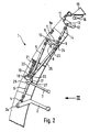
- FIG. 1 shows a side view of a locking arrangement for an aircraft door 1 with an inner lever 2, an emergency slide control lever 3, the inner lever 2, which can be pivoted about a point 2a closest to the door, having an articulation point 4 in which a connecting rod 5 is articulated.
- a lever 7 with a hinge point 9 and a lever 7 with a hinge point 10 are pivotally mounted with a door-mounted locking shaft 6. Close both levers 7 and 7a as shown, an angle and are rigidly connected to the shaft 6, wherein a driving lever 8 is connected to the shaft 6 in the same way.
- the arrangement consisting of the lever 7 and the rod 14 is in principle provided twice in the example embodiment shown, as will be shown. Due to the two-dimensional representations, this is not taken into account here for the sake of simplicity.
- a locking hook 12 which has a connection point 13 is pivotally mounted about another point 11 that is fixed to the door. Points 9 and 13 are articulated to one another by a locking rod 14.
- two brackets 15 are arranged, each with an eyelet fitting 16, into which the hooks 12 can engage.
- a blocking hook 17 is arranged pivotably about a point 16 that is closest to the door and has two articulation points 19 and 20.
- the door 1 also has a point 21, in which a rod-shaped compression spring 22 engages with one end. The other end of the spring 22 is articulated at point 19 on the hook 17, so that the hook 17 is given a clockwise torque about the point 18.
- a lever 23 with an articulation point 24 is pivotally arranged about the axis 6, in which the first end of a rod 25 engages, the second end of which is articulated to the hook-side point 20.
- the operating lever 3 for an emergency slide of known type can be pivoted about a point 26 and has an engagement surface 27.
- the aircraft door 1 In the open state, the aircraft door 1 is outside the fuselage structure. To close this door 1 is pivoted from the outside into the fuselage structure, the hook 12 being in its lower position so that it can pass through the eyelet 16. After swiveling in, the door 1 is lowered into the positive position by swiveling the inner lever 2 downward about the point 2a closest to the door. The lever 7 is rotated counterclockwise via the rod 5 and the shaft 6, as a result of which the hook 12 swings upwards until it enters the eyelet 16 intervenes. The lever 7 and the rod 14 form a toggle lever arrangement arranged between the locking shaft 6 and the connection point 13.
- the driving lever 8 is arranged near the lever 23 and is designed in such a way that when it turns to the left it bears against the lever 23 and takes it along.
- the blocking hook 17 is pivoted counterclockwise about the point 18 by means of the rod 25.
- the design of the driving lever 8 and the lever 23 ensures that the blocking hook 17 is brought into the position shown when properly locked, ie when the toggle lever arrangement 7 and 14 is engaged.
- the emergency slide must be made operational so that it can be put into operation if necessary.
- the emergency slide control lever 3 must be swiveled clockwise from the position shown.
- the state of the lock is checked. The following procedure results.
- the lever 7 is rotated counterclockwise until the knee joint 9 touches the stop 9a and is thus in the locked position.
- the loose seated lever 23 raised by the driving lever 8 so that the blocking hook 17 is brought into the position shown by means of the rod 25.
- FIG. 2 shows the arrangement according to FIG. 1 with the elements described above, the two levers 2 and 3 having already been brought into the opening position, for example in order to open the door 1 after a landing.
- the inner lever 2 was first pivoted counterclockwise, the lever 7 being given a clockwise rotation via the rod 5 and the shaft 6, so that the locking hook 12 now assumes the unlocked position shown.
- the driving lever 8 lifts off the lever 23, so that the blocking hook 17 comes into its lower position shown as a result of the compression spring 22.
- the emergency slide control lever 3 is pivoted upwards, the blocking hook 17 engages behind the engagement surface 27, so that the lever 2 can only be brought back into its ready-to-take off position when the door 1 has been locked for the next flight.
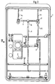
- Figure 3 shows the view III of the door 1 of Fig. 1, with the inner panel and the suspension arm removed, so that the aforementioned elements, such as the inner lever 2, the emergency slide control lever 3, the rod 5, the locking shaft 6 and the rod 25 are visible .
- the shaft 6 is supported at its ends and has the lever 7a in its center. Near the ends of the shaft 6, the levers 7 and 7 'are arranged, which are operatively connected to the locking hooks 12 and 12' via the rods 14 and 14 '.
- Figure 4 shows the view IV of the door 1 in the open state.
- the door 1 is pivoted out of the fuselage structure 28 by means of a supporting link 29 and is located outside the fuselage next to the door opening.
- Two guide links 30 and 31 are provided to stabilize the pivoting movement.
- the picture also shows fuselage-side fitting fittings 32 and door-side fitting fittings 33 and the emergency slide container 34.
- the door 1 In the non-closed state, the door 1 is raised by the dimension d compared to its position in the closed state. To close the door 1, it is first pivoted into the fuselage structure 28 and then lowered by the dimension d mentioned. As a result, the door-side contact fittings 33 each reach positions in which each fitting 33 is opposite a fuselage-side contact fitting 32 in the radial direction to the outside.
- the emergency slide container 34 contains the emergency slide required for rapid evacuation of the aircraft and is generally locked to the lower region of the door 1.
- the picture shows the emergency slide in this state with door 1 open. This configuration is always present when door 1 has been opened after normal landing without operating lever 3. If it is necessary for the aircraft to be cleared quickly by the passengers, the emergency slide will be in front opened the door by means of the lever 3 in the operational state. In a known manner, the door-side bracket of the emergency slide is released and a corresponding fuselage-side bracket is locked, so that the emergency slide in this case remains connected to the door sill in question for the further functional sequence.
- the invention also extends to aircraft doors, the structural design of which differs from the exemplary embodiment shown, provided that they only have one operating element for an emergency slide.
- the invention can also be applied to doors, the door load being transmitted to the fuselage structure via correspondingly dimensioned edges of the door instead of via fitting fittings 32 and 33.
- other equivalent blocking elements are also conceivable, such as, for example, a pin which can be displaced axially or radially with respect to the axis 26 and which can be inserted into a corresponding axis-fixed bore.
- the invention is thus not limited to the exemplary embodiment shown and described. Rather, it extends to all configurations that are conceivable within the scope of the claims.
Abstract
Description
Die Erfindung bezieht sich auf eine Verriegelung nach dem Oberbegriff des Anspruchs 1.The invention relates to a lock according to the preamble of claim 1.
Flugzeugtüren unterliegen strengen Sicherheitsvorschriften, um Unfälle durch nicht verriegelte Flugzeugtüren zu vermeiden. So verlangen die neuesten Empfehlungen und Richlinien für die Konstruktion innendruckbeaufschlagter Flugzeugtüren, daß entsprechende Vorkehrungen zur Überprüfung der vollständigen und sicheren Verriegelung vorgesehen sind. Eine denkbare Vorkehrung dieser Art kann beispielsweise darin bestehen, daß eine Entlüftungsklappe angeordnet ist, wodurch bei nicht vollständig verriegelter Tür der Aufbau des Innendruckes verhindert wird, so daß die schadhafte Verriegelung durch den nicht erfolgenden Druckaufbau bemerkt werden kann. Eine derartige Lösung, wobei die Kontrolle der Türverriegelung auf dem Wege über eine Kontrolle des Kabinendruckes erfolgt, wäre mit einem erheblichen Aufwand an zusätzlichen Einbauten verbunden, was aus Gewichts- und Kostengründen ungünstig wäre. Außerdem würde bei einer derartigen Kontrolle der Verriegelung zwischen dem Verriegeln und dem Anzeigen einer schadhaften Verriegelung eine bestimmte Zeitspanne vergehen, so daß entsprechende Abhilfe-Maßnahmen erst mit einer Verzögerung eingeleitet werden können.Aircraft doors are subject to strict safety regulations to avoid accidents caused by unlocked aircraft doors. For example, the latest recommendations and guidelines for the construction of aircraft doors subject to internal pressure require that appropriate precautions be taken to check that they are fully and securely locked. A conceivable precaution of this type can consist, for example, in that a ventilation flap is arranged, as a result of which the build-up of the internal pressure is prevented when the door is not completely locked, so that the defective locking can be noticed by the pressure buildup not taking place. Such a solution, the control of the door locking taking place by way of a control of the cabin pressure, would be associated with a considerable outlay in additional installations, which would be disadvantageous for reasons of weight and cost. In addition, with such a control of the locking between the locking and the display of a defective locking, a certain period of time would pass, so that appropriate remedial measures can only be initiated with a delay.
Demgemäß liegt der Erfindung die Aufgabe zugrunde, eine gattungsgemäße Verriegelung derart auszubilden, daß diese sehr einfach herzustellen ist und bezüglich Gewicht und Kosten Vor teile gegenüber anderen Lösungen aufweist, wobei eine unvollständige Verriegelung der Tür bei deren Schließen sofort erkannt wird.Accordingly, the invention has for its object to provide a generic lock such that it is very easy to manufacture and in terms of weight and cost parts compared to other solutions, whereby an incomplete locking of the door is immediately recognized when it is closed.
Diese Aufgabe wird bei einer gattungsgemäßen Verriegelung durch die kennzeichnenden Merkmale des Patentanspruchs 1 gelöst. Danach ist vorgesehen, daß der Bedienhebel, womit die letzte Bedienungsmaßnahme durchgeführt wird, mit der Verriegelung derart zusammenwirkt, daß der Zustand der Verriegelung, insbesondere mittels des Bedienhebels für die Notrutsche, überprüfbar ist. Vorteilhafte Weiterbildungen der Erfindung sind in den Unteransprüchen angegeben.This object is achieved in a generic lock by the characterizing features of claim 1. According to this, it is provided that the operating lever, with which the last operating measure is carried out, cooperates with the locking device in such a way that the state of the locking device, in particular by means of the operating lever for the emergency slide, can be checked. Advantageous developments of the invention are specified in the subclaims.
Die Erfindung ist anhand der Zeichnung dargestellt und in der Beispielbeschreibung näher erläutert. Es zeigen
- Fig. 1 eine Übersichtsdarstellung einer Verriegelung für eine Flugzeugtür,
- Fig. 2 die Verriegelung nach Fig. 1 in Öffnungsstellung,
- Fig. 3 die Ansicht III nach Fig. 1 und
- Fig. 4 die Ansicht IV nach Fig. 3.
- 1 is an overview of a lock for an aircraft door,
- 2 shows the lock according to FIG. 1 in the open position,
- Fig. 3 is the view III of Fig. 1 and
- 4 shows the view IV according to FIG. 3.
Figur 1 zeigt eine Seitenansicht einer Verriegelungsanordnung für eine Flugzeugtür 1 mit einem Innenhebel 2, einem Notrutschenbedienhebel 3, wobei der Innenhebel 2, der um einen türfesten Punkt 2a schwenkbar ist, einen Gelenkpunkt 4 aufweist, in dem eine Verbindungsstange 5 angelenkt ist. Mit einer türfest gelagerten Verriegelungswelle 6 sind ein Hebel 7 mit einem Gelenkpunkt 9 und ein Hebel 7 ja mit einem Gelenkpunkt 10 schwenkbar gelagert. Beide Hebel 7 und 7a schließen, wie gezeigt, einen Winkel ein und sind starr mit der Welle 6 verbunden, wobei ein Mitnahmehebel 8 in gleicher Weise mit der Welle 6 verbunden ist. Die aus dem Hebel 7 und der Stange 14 bestehende Anordnung ist bei der gezeigten Beispielausführung im Prinzip zweifach vorgesehen, wie noch gezeigt wird. Aufgrund der zweidimensionalen Darstellungen wird dies der Einfachheit halber hier jedoch nicht berücksichtigt. Im Gelenkpunkt 10 des Hebels 7a greift die Stange 5 an. Um einen anderen türfesten Punkt 11 ist ein Verriegelungshaken 12 schwenkbar gelagert, der einen Anschlußpunkt 13 aufweist. Die Punkte 9 und 13 sind durch eine Verriegelungsstange 14 gelenkig miteinander verbunden. Seitens der Rumpfstruktur sind zwei Halterungen 15 mit je einem Ösenbeschlag 16 angeordnet, in die die Haken 12 eingreifen können. Ein Blockierhaken 17 ist um einen türfesten Punkt 16 schwenkbar angeordnet und weist zwei Gelenkpunkte 19 und 20 auf. Die Tür 1 weist weiterhin einen Punkt 21 auf, in dem eine stangenförmige Druckfeder 22 mit ihrem einen Ende angreift. Das andere Ende der Feder 22 ist im Punkt 19 am Haken 17 angelenkt, so daß dem Haken 17 ein rechtsdrehendes Moment um den Punkt 18 erteilt wird. Um die Achse 6 ist ein Hebel 23 mit einem Gelenkpunkt 24 schwenkbar angeordnet, in dem das erste Ende einer Stange 25 angreift, deren zweites Ende mit dem hakenseitigen Punkt 20 gelenkig verbunden ist. Der Bedienhebel 3 für eine Notrutsche bekannter Art ist um einen Punkt 26 schwenkbar und weist eine Eingriffsfläche 27 auf.FIG. 1 shows a side view of a locking arrangement for an aircraft door 1 with an
In geöffnetem Zustand befindet sich die Flugzeugtür 1 außerhalb der Rumpfstruktur. Zum Schließen wird diese Tür 1 von außen in die Rumpfstruktur eingeschwenkt, wobei sich der Haken 12 in seiner unteren Position befindet, so daß er die Öse 16 passieren kann. Nach dem Einschwenken wird die Tür 1 durch Abwärtsschwenken des Innenhebels 2 um den türfesten Punkt 2a in die formschlüssige Position abgesenkt. Dabei wird der Hebel 7 über die Stange 5 und die Welle 6 entgegen dem Uhrzeigersinne gedreht, wodurch der Haken 12 nach oben ausschwenkt, bis er in die Öse 16 eingreift. Der Hebel 7 und die Stange 14 bilden eine zwischen der Verriegelungswelle 6 und dem Anschlußpunkt 13 angeordnete Kniehebelanordnung. Beim Abwärtsschwenken des Innenhebels 2 durchwandert der Kniegelenkpunkt 9 bei seiner Linksdrehung die Verbindungslinie der Punkte 6 und 13 und kommt, wie gezeigt, um eine definierte Strecke links von der Linie infolge eines Anschlages 9a zur Ruhe. In dieser eingerasteten Lage der Kniehebelanordnungen befindet sich der Innenhebel 2 in der gezeigten Position und die Tür 1 ist über den Haken 12 infolge des Kniehebeleffektes mit der Rumpfstruktur automatisch, d.h. ohne Ausführung einer besonderen Bedienungsmaßnahme ordnungsgemäß verriegelt. Bei der Linksdrehung des Hebels 7 wird außer den Gelenkpunkten 9 auch der starr damit verbundene Mitnahmehebel 8 gedreht. In der Endphase dieser Drehung wird auch der lose auf der Verriegelungswelle 6 sitzende Hebel 23 mitgenommen. Dies wird dadurch erreicht, daß der Mitnahmehebel 8 nahe dem Hebel 23 angeordnet und derart ausgebildet ist, daß er sich bei seiner Linksdrehung an den Hebel 23 anlegt und diesen mitnimmt. Hierdurch wird der Blockierhaken 17 mittels der Stange 25 entgegen dem Uhrzeigersinne um den Punkt 18 geschwenkt.In the open state, the aircraft door 1 is outside the fuselage structure. To close this door 1 is pivoted from the outside into the fuselage structure, the
Aufgrund der Gestaltung des Mitnahmehebels 8 und des Hebels 23 ist sichergestellt, daß der Blockierhaken 17 bei ordnungsgemäßer Verriegelung, d.h. bei eingrasteter Kniehebelanordnung 7 und 14 in die gezeigte Position gebracht wird. Entsprechend der festgelegten Vorgehensweise beim Start eines Flugzeuges ist nach dem Schließen und Verriegeln der Tür 1 die Notrutsche betriebsklar zu machen, damit diese bei Bedarf in Funktion gesetzt werden kann. Hierzu ist der Notrutschenbedienhebel 3 aus der gezeigten Stellung im Uhrzeigersinn nach unten zu schwenken. Erfindungsgemäß wird dabei der Zustand der Verriegelung überprüft. Dabei ergibt sich folgender Ablauf. Beim ordnungsgemäßen Verriegeln der Tür 1 wird der Hebel 7 entgegen dem Uhrzeigersinn gedreht, bis das Kniegelenk 9 den Anschlag 9a berührt und sich damit in der verriegelten Position befindet. Dabei wird zugleich der lose sitzende Hebel 23 durch den Mitnahmehebel 8 angehoben, so daß der Blockierhaken 17 mittels der Stange 25 in die gezeigte Position gebracht wird. In dieser für eine ordnungsgemäße Verriegelung charakteristischen Position des Blockierhakens 17 kann nun der Hebel 3 ohne weiteres nach unten geschwenkt werden und die Tür ist in abflugbereitem Zustand. Im Gegensatz dazu zeigt sich eine schadhafte Verriegelung dadurch, daß das Kniegelenk 9 nicht am Anschlag 9a anliegt und der Mitnahmehebel 8 demzufolge nicht über den Hebel 23 und die Stange 25 auf den Haken 17 einwirkt, um diesen anzuheben. Daher verbleibt der Blockierhaken 17 unter der Wirkung der Feder 22 in seiner unteren für eine nicht ordnungsgemäße Verriegelung der Tür 1 charakteristischen Position. Bei dem Versuch, die Tür 1 durch Betätigen des Hebels 3 in einen abflugbereiten Zustand zu bringen, greift der Blockierhaken 17 demgemäß in die Eingriffsfläche 27 ein. Hierdurch wird eine Schwenkung des Hebels 3 in die Abflugposition so lange verhindert, bis die Verriegelung geklärt ist.The design of the driving lever 8 and the
Figur 2 zeigt die Anordnung nach Fig. 1 mit den vorbeschriebenen Elementen, wobei die beiden Hebel 2 und 3 bereits in Öffnungsposition gebracht sind, etwa um die Tür 1 nach einer Landung zu öffnen. Hierzu wurde zunächst der Innenhebel 2 entgegen dem Uhrzeigersinn geschwenkt, wobei dem Hebel 7 über die Stange 5 und die Welle 6 eine Rechtsdrehung erteilt wurde, so daß der Verriegelungshaken 12 jetzt die gezeigte entriegelte Stellung einnimmt. Bei dieser Betätigung des Innenhebels 2 hebt der Mitnahmehebel 8 vom Hebel 23 ab, so daß der Blockierhaken 17 infolge der Druckfeder 22 in seine gezeigte untere Position gelangt. Beim Aufwärtsschwenken des Notrutschenbedienhebels 3 rastet der Blockierhaken 17 hinter der Eingriffsfläche 27 ein, so daß der Hebel 2 erst wieder in seine abflugbereite Stellung gebracht werden kann, wenn die Tür 1 für den nächsten Flug verriegelt worden ist.FIG. 2 shows the arrangement according to FIG. 1 with the elements described above, the two levers 2 and 3 having already been brought into the opening position, for example in order to open the door 1 after a landing. For this purpose, the
Figur 3 zeigt die Ansicht III der Tür 1 nach Fig. 1, wobei die Innenverkleidung und der Traglenker entfernt sind, so daß die vorgenannten Elemente, wie der Innenhebel 2, der Notrutschenbedienhebel 3 die Stange 5, die Verriegelungswelle 6 und die Stange 25 sichtbar sind. Die Welle 6 ist an ihren Enden gelagert und weist in ihrer Mitte den Hebel 7a auf. Nahe den Enden der Welle 6 sind die Hebel 7 und 7′ angeordnet, die über die Stangen 14 und 14′ mit den Verriegelungshaken 12 und 12′ in Wirkverbindung stehen.Figure 3 shows the view III of the door 1 of Fig. 1, with the inner panel and the suspension arm removed, so that the aforementioned elements, such as the
Figur 4 zeigt die Ansicht IV der Tür 1 in geöffnetem Zustand. Dabei ist die Tür 1 aus der Rumpfstruktur 28 anhand eines Traglenkers 29 herausgeschwenkt und befindet sich außerhalb des Rumpfes neben der Türöffnung. Zur Stabilisierung der Schwenkbewegung sind zwei Führungslenker 30 und 31 vorgesehen. Das Bild zeigt weiterhin rumpfseitige Anlagebeschläge 32 und türseitige Anlagebeschläge 33 sowie den Notrutschenbehälter 34. In nicht geschlossenem Zustand ist die Tür 1 gegenüber ihrer Position in geschlossenem Zustand um das Maß d angehoben. Zum Schließen der Tür 1 wird diese zunächst in die Rumpfstruktur 28 eingeschwenkt und dann um das genannte Maß d abgesenkt. Hierdurch gelangen die türseitigen Anlagebeschläge 33 jeweils in Positionen, in denen jedem Beschlag 33 in radialer Richtung nach außen ein rumpfseitiger Anlagebeschlag 32 gegenüberliegt. Bei Auftreten eines gegenüber der Umgebung wirkenden Kabinendruckes wird die infolge der Druckdifferenz auf die Tür 1 wirkende Last über die Beschläge 32 und 33 formschlüssig auf die Rumpfstruktur 28 übertragen. Der Notrutschenbehälter 34 enthält die für eine schnelle Evakuierung des Flugzeuges erforderliche Notrutsche und ist im Regelfall mit dem unteren Bereich der Tür 1 verriegelt. Das Bild zeigt die Notrutsche in diesem Zustand bei geöffneter Tür 1. Diese Konfiguration liegt immer dann vor, wenn die Tür 1 nach einer normalen Landung ohne Betätigung des Hebels 3 geöffnet worden ist. Sollte es erforderlich sein, daß das Flugzeug von den Passagieren rasch zu räumen ist, so wird die Notrutsche vor dem Öffnen der Tür mittels des Hebels 3 in den betriebsbereiten Zustand gebracht. In bekannter Weise wird dabei die türseitige Halterung der Notrutsche gelöst und eine entsprechende rumpfseitige Halterung verriegelt, so daß die Notrutsche in diesem Falle mit dem betreffenden Türschweller für den weiteren Funktionsablauf verbunden bleibt.Figure 4 shows the view IV of the door 1 in the open state. The door 1 is pivoted out of the
Die Erfindung erstreckt sich auch auf Flugzeugtüren, deren konstruktive Gestaltung von der gezeigten Beispielausführung abweicht, sofern sie nur ein Bedienungselement für eine Notrutsche aufweisen. So ist die Erfindung auch auf Türen anwendbar, wobei die Türlast anstatt über Anlagebeschläge 32 und 33 über entsprechend dimensionierte Ränder der Tür auf die Rumpfstruktur übertragen wird. Anstelle des Blockierhakens 17 sind auch andere gleichwertige Blockierelemente denkbar, wie beispielsweise ein in bezug auf die Achse 26 axial oder radial verschiebbarer Stift, der in eine entsprechende achsenfeste Bohrung einschiebbar ist. Gleiches gilt für die Feder 22, die prinzipiell durch eine Zugfeder oder eine Schenkelfeder ersetzbar ist. Die Erfindung ist somit nicht auf die dargestellte und beschriebene Beispielausführung beschränkt. Sie erstreckt sich vielmehr auf alle Ausgestaltungen, die im Rahmen der Ansprüche denkbar sind.The invention also extends to aircraft doors, the structural design of which differs from the exemplary embodiment shown, provided that they only have one operating element for an emergency slide. Thus, the invention can also be applied to doors, the door load being transmitted to the fuselage structure via correspondingly dimensioned edges of the door instead of via
Claims (2)
Applications Claiming Priority (2)
| Application Number | Priority Date | Filing Date | Title |
|---|---|---|---|
| DE3807067A DE3807067A1 (en) | 1988-03-04 | 1988-03-04 | LOCK FOR AN AIRPLANE DOOR |
| DE3807067 | 1988-03-04 |
Publications (3)
| Publication Number | Publication Date |
|---|---|
| EP0330814A2 true EP0330814A2 (en) | 1989-09-06 |
| EP0330814A3 EP0330814A3 (en) | 1990-07-18 |
| EP0330814B1 EP0330814B1 (en) | 1993-05-05 |
Family
ID=6348843
Family Applications (1)
| Application Number | Title | Priority Date | Filing Date |
|---|---|---|---|
| EP89100373A Expired - Lifetime EP0330814B1 (en) | 1988-03-04 | 1989-01-11 | Locking system for an aircraft door |
Country Status (4)
| Country | Link |
|---|---|
| US (1) | US4944473A (en) |
| EP (1) | EP0330814B1 (en) |
| DE (1) | DE3807067A1 (en) |
| ES (1) | ES2056960T3 (en) |
Cited By (3)
| Publication number | Priority date | Publication date | Assignee | Title |
|---|---|---|---|---|
| EP0677438A1 (en) * | 1994-04-16 | 1995-10-18 | EUROCOPTER DEUTSCHLAND GmbH | Door system, in particular for a passenger aircraft |
| US5518206A (en) * | 1992-05-22 | 1996-05-21 | Short Brothers Plc | Closure default indicator |
| CN103883183A (en) * | 2012-12-21 | 2014-06-25 | 中国直升机设计研究所 | Embedded-type latch mechanism and helicopter hatch door |
Families Citing this family (27)
| Publication number | Priority date | Publication date | Assignee | Title |
|---|---|---|---|---|
| US5064147A (en) * | 1990-02-12 | 1991-11-12 | The Boeing Company | Upwardly opening plug-type door for use as an over-wing emergency hatch |
| DE4022067C2 (en) * | 1990-07-11 | 1994-06-09 | Deutsche Aerospace Airbus | Kinematics for an aircraft door |
| US5305969A (en) * | 1991-07-16 | 1994-04-26 | The Boeing Company | Aircraft door latch lock mechanism |
| DE4124377C1 (en) * | 1991-07-23 | 1992-12-17 | Deutsche Airbus Gmbh, 2000 Hamburg, De | Aircraft door emergency opening device - has actuator cylinder to swing door outwards and pyrotechnic device may be used |
| DE4200930C1 (en) * | 1992-01-16 | 1993-01-28 | Deutsche Airbus Gmbh, 2000 Hamburg, De | |
| US5337977A (en) * | 1993-01-29 | 1994-08-16 | The Boeing Company | Vent-latch interlock assembly for an aircraft door |
| DE19702084C1 (en) * | 1997-01-22 | 1998-02-19 | Eurocopter Deutschland | Operating system for pressurised aeroplane plug type door |
| IT1302159B1 (en) * | 1997-09-03 | 2000-07-31 | Eurocopter Deutschland | DOOR SYSTEM FOR A PASSENGER AIRCRAFT |
| US6604014B1 (en) * | 1998-03-02 | 2003-08-05 | Triodyne Safety Systems L.L.C. | Remote and proximal guard testing systems and testing systems either separately or in conjunction with interlock testing mechanisms and systems |
| GB2370822B (en) * | 2001-01-04 | 2005-05-18 | Aircraft Materials Ltd | Airborne platform apparatus |
| DE10116224B4 (en) * | 2001-03-30 | 2005-12-01 | Eurocopter Deutschland Gmbh | Method and device for adjusting a door-side securing device of an aircraft door |
| FR2835235B1 (en) * | 2002-01-31 | 2004-04-09 | Airbus France | EJECTABLE DOOR, FOR AIRCRAFT |
| US20080272607A1 (en) * | 2007-05-01 | 2008-11-06 | John Trouy Kannapell | Dual release actuator assembly |
| RU2482018C2 (en) * | 2007-07-31 | 2013-05-20 | Б/Е Аэроспейс, Инк. | Aircraft door |
| US8047583B2 (en) * | 2007-10-04 | 2011-11-01 | B/E Aerospace, Inc. | Split handle for aircraft door |
| DE102008020789A1 (en) * | 2008-04-25 | 2009-11-05 | Airbus Deutschland Gmbh | Mounting system and method for attaching an element of an aircraft interior trim |
| DE102010013715B4 (en) * | 2010-04-02 | 2015-01-15 | Airbus Operations Gmbh | An aircraft door latch mechanism, method of locking an aircraft door and aircraft door |
| EP2872395B1 (en) | 2012-07-11 | 2016-10-05 | Tusas-Türk Havacilik Ve Uzay Sanayii A.S. | Aircraft comprising a sliding door with a locking mechanism |
| CN103382795A (en) * | 2013-03-21 | 2013-11-06 | 陕西飞机工业(集团)有限公司 | Airplane cargo bridge door locking mechanism |
| CN103552695B (en) * | 2013-11-05 | 2016-03-09 | 中国航空工业集团公司西安飞机设计研究所 | A kind of test method verifying cargo door opening and closing function |
| EP3168138B1 (en) * | 2015-11-10 | 2018-06-06 | Airbus Operations GmbH | Aircraft door assembly |
| EP3168139B1 (en) * | 2015-11-10 | 2018-01-10 | Airbus Operations GmbH | Aircraft door assembly |
| US10689089B2 (en) * | 2016-04-01 | 2020-06-23 | Textron Innovations, Inc. | Entry handle for an aircraft doorway |
| CN106741833B (en) * | 2016-12-29 | 2019-03-15 | 中航沈飞民用飞机有限责任公司 | Upper and lower opening type escape hatch right-hand side handle mechanism |
| US11358702B2 (en) * | 2019-01-11 | 2022-06-14 | The Boeing Company | Aircraft security door and method and apparatus for security door handling |
| EP3858726B1 (en) * | 2020-01-28 | 2022-08-31 | AIRBUS HELICOPTERS DEUTSCHLAND GmbH | An actuating system for an actuatable door |
| EP3871971B1 (en) * | 2020-02-25 | 2022-02-16 | AIRBUS HELICOPTERS DEUTSCHLAND GmbH | An actuating system for an actuatable door |
Citations (2)
| Publication number | Priority date | Publication date | Assignee | Title |
|---|---|---|---|---|
| US4125235A (en) * | 1977-04-04 | 1978-11-14 | The Boeing Company | Apparatus for opening an aircraft door and for arming and disarming an escape slide deploying mechanism |
| EP0188825A2 (en) * | 1985-01-24 | 1986-07-30 | The Boeing Company | Translatable outward opening plug-type aircraft door and actuating mechanism |
Family Cites Families (3)
| Publication number | Priority date | Publication date | Assignee | Title |
|---|---|---|---|---|
| WO1984001340A1 (en) * | 1982-09-30 | 1984-04-12 | Boeing Co | Door locking mechanism |
| FR2548623B1 (en) * | 1983-07-08 | 1985-10-11 | Aerospatiale | SAFETY DEVICE FOR OPENING AN AIRCRAFT DOOR OPENING OUTSIDE IN THE EVENT OF AN OVERPRESSURE INSIDE THIS AIRCRAFT AND DOOR THUS EQUIPPED |
| DE3539480A1 (en) * | 1985-11-07 | 1987-05-14 | Messerschmitt Boelkow Blohm | OPERATING DEVICE FOR A FREIGHT LOADING GATE |
-
1988
- 1988-03-04 DE DE3807067A patent/DE3807067A1/en active Granted
-
1989
- 1989-01-11 ES ES89100373T patent/ES2056960T3/en not_active Expired - Lifetime
- 1989-01-11 EP EP89100373A patent/EP0330814B1/en not_active Expired - Lifetime
- 1989-03-02 US US07/317,945 patent/US4944473A/en not_active Expired - Lifetime
Patent Citations (2)
| Publication number | Priority date | Publication date | Assignee | Title |
|---|---|---|---|---|
| US4125235A (en) * | 1977-04-04 | 1978-11-14 | The Boeing Company | Apparatus for opening an aircraft door and for arming and disarming an escape slide deploying mechanism |
| EP0188825A2 (en) * | 1985-01-24 | 1986-07-30 | The Boeing Company | Translatable outward opening plug-type aircraft door and actuating mechanism |
Cited By (4)
| Publication number | Priority date | Publication date | Assignee | Title |
|---|---|---|---|---|
| US5518206A (en) * | 1992-05-22 | 1996-05-21 | Short Brothers Plc | Closure default indicator |
| EP0677438A1 (en) * | 1994-04-16 | 1995-10-18 | EUROCOPTER DEUTSCHLAND GmbH | Door system, in particular for a passenger aircraft |
| CN103883183A (en) * | 2012-12-21 | 2014-06-25 | 中国直升机设计研究所 | Embedded-type latch mechanism and helicopter hatch door |
| CN103883183B (en) * | 2012-12-21 | 2016-08-10 | 中国直升机设计研究所 | A kind of built-in bolt mechanism and helicopter hatch door |
Also Published As
| Publication number | Publication date |
|---|---|
| EP0330814A3 (en) | 1990-07-18 |
| US4944473A (en) | 1990-07-31 |
| ES2056960T3 (en) | 1994-10-16 |
| DE3807067C2 (en) | 1990-05-17 |
| DE3807067A1 (en) | 1989-09-14 |
| EP0330814B1 (en) | 1993-05-05 |
Similar Documents
| Publication | Publication Date | Title |
|---|---|---|
| EP0330814B1 (en) | Locking system for an aircraft door | |
| EP1713712B1 (en) | Device for actuating and locking elevator doors | |
| DE10020825B4 (en) | Method and device for closing a door of an aircraft | |
| EP1497217B1 (en) | Device for actuating and locking elevator doors comprising driving runners | |
| AT500017B1 (en) | SWIVEL SLIDING DOOR FOR VEHICLES | |
| DE3539480C2 (en) | ||
| WO2008064650A2 (en) | Door lock for doors of aircraft, especially of helicopters | |
| DE2914469C2 (en) | Actuating device for a flap, which is arranged pivotably in particular on an aircraft cell, a spacecraft or the like and in particular serves to close an air intake opening for the starter turbine of an aircraft engine | |
| EP4069922B1 (en) | Motor vehicle lock, in particular motor vehicle door lock | |
| DE1653994B2 (en) | Motor vehicle door lock | |
| EP1816298A1 (en) | Slidable folding shutter | |
| DE60212897T2 (en) | Quick release device for an electric bus door | |
| DE102019112336B4 (en) | Door unit for a vehicle | |
| DE1905074C2 (en) | Window casement with ventilating flap locking mechanism - has swivelling and setting arm pairs forming two armed elbow levers | |
| DE102016002614A1 (en) | Pivoting device for a turn-tilt wing of a window or a door for motorized tilting and manual turning and tilting | |
| EP0643790B1 (en) | Access lock for authorized persons | |
| DE19609109B4 (en) | Airplane pilot room with emergency exit accessible from outside | |
| DE2904987C2 (en) | Fitting for tilt and swivel sashes of windows, doors or the like. | |
| DE102011109652A1 (en) | Support arm arrangement, door and means of transport | |
| EP0505350A1 (en) | Pivoting plate-closure sequence and locking device | |
| DE2932865A1 (en) | Roof window wing fitting - has torsion spring assembly connected to one frame and force locked to other | |
| WO2024041699A1 (en) | Motor vehicle lock | |
| DE3815707C2 (en) | Locking a horizontally divided door, especially for caravans and the like | |
| DE3513492C2 (en) | ||
| DE4447085A1 (en) | Folding step for rail vehicle door |
Legal Events
| Date | Code | Title | Description |
|---|---|---|---|
| PUAI | Public reference made under article 153(3) epc to a published international application that has entered the european phase |
Free format text: ORIGINAL CODE: 0009012 |
|
| AK | Designated contracting states |
Kind code of ref document: A2 Designated state(s): ES FR GB IT |
|
| PUAL | Search report despatched |
Free format text: ORIGINAL CODE: 0009013 |
|
| AK | Designated contracting states |
Kind code of ref document: A3 Designated state(s): ES FR GB IT |
|
| 17P | Request for examination filed |
Effective date: 19900712 |
|
| RAP1 | Party data changed (applicant data changed or rights of an application transferred) |
Owner name: DEUTSCHE AIRBUS GMBH |
|
| 17Q | First examination report despatched |
Effective date: 19910820 |
|
| GRAA | (expected) grant |
Free format text: ORIGINAL CODE: 0009210 |
|
| RAP1 | Party data changed (applicant data changed or rights of an application transferred) |
Owner name: DEUTSCHE AEROSPACE AIRBUS GMBH |
|
| AK | Designated contracting states |
Kind code of ref document: B1 Designated state(s): ES FR GB IT |
|
| GBT | Gb: translation of ep patent filed (gb section 77(6)(a)/1977) |
Effective date: 19930621 |
|
| ET | Fr: translation filed | ||
| ITF | It: translation for a ep patent filed |
Owner name: STUDIO JAUMANN |
|
| PLBE | No opposition filed within time limit |
Free format text: ORIGINAL CODE: 0009261 |
|
| STAA | Information on the status of an ep patent application or granted ep patent |
Free format text: STATUS: NO OPPOSITION FILED WITHIN TIME LIMIT |
|
| 26N | No opposition filed | ||
| REG | Reference to a national code |
Ref country code: ES Ref legal event code: FG2A Ref document number: 2056960 Country of ref document: ES Kind code of ref document: T3 |
|
| REG | Reference to a national code |
Ref country code: GB Ref legal event code: IF02 |
|
| PGFP | Annual fee paid to national office [announced via postgrant information from national office to epo] |
Ref country code: ES Payment date: 20080130 Year of fee payment: 20 |
|
| PGFP | Annual fee paid to national office [announced via postgrant information from national office to epo] |
Ref country code: GB Payment date: 20080124 Year of fee payment: 20 Ref country code: IT Payment date: 20080125 Year of fee payment: 20 |
|
| PGFP | Annual fee paid to national office [announced via postgrant information from national office to epo] |
Ref country code: FR Payment date: 20080111 Year of fee payment: 20 |
|
| REG | Reference to a national code |
Ref country code: GB Ref legal event code: PE20 Expiry date: 20090110 |
|
| REG | Reference to a national code |
Ref country code: ES Ref legal event code: FD2A Effective date: 20090112 |
|
| PG25 | Lapsed in a contracting state [announced via postgrant information from national office to epo] |
Ref country code: GB Free format text: LAPSE BECAUSE OF EXPIRATION OF PROTECTION Effective date: 20090110 |
|
| PG25 | Lapsed in a contracting state [announced via postgrant information from national office to epo] |
Ref country code: ES Free format text: LAPSE BECAUSE OF EXPIRATION OF PROTECTION Effective date: 20090112 |