EP0330502A2 - Anzeigeschildanordung - Google Patents
Anzeigeschildanordung Download PDFInfo
- Publication number
- EP0330502A2 EP0330502A2 EP89301871A EP89301871A EP0330502A2 EP 0330502 A2 EP0330502 A2 EP 0330502A2 EP 89301871 A EP89301871 A EP 89301871A EP 89301871 A EP89301871 A EP 89301871A EP 0330502 A2 EP0330502 A2 EP 0330502A2
- Authority
- EP
- European Patent Office
- Prior art keywords
- sign
- component
- post
- nesting
- slot
- Prior art date
- Legal status (The legal status is an assumption and is not a legal conclusion. Google has not performed a legal analysis and makes no representation as to the accuracy of the status listed.)
- Withdrawn
Links
Images


Classifications
-
- G—PHYSICS
- G09—EDUCATION; CRYPTOGRAPHY; DISPLAY; ADVERTISING; SEALS
- G09F—DISPLAYING; ADVERTISING; SIGNS; LABELS OR NAME-PLATES; SEALS
- G09F7/00—Signs, name or number plates, letters, numerals, or symbols; Panels or boards
- G09F7/18—Means for attaching signs, plates, panels, or boards to a supporting structure
-
- G—PHYSICS
- G09—EDUCATION; CRYPTOGRAPHY; DISPLAY; ADVERTISING; SEALS
- G09F—DISPLAYING; ADVERTISING; SIGNS; LABELS OR NAME-PLATES; SEALS
- G09F7/00—Signs, name or number plates, letters, numerals, or symbols; Panels or boards
-
- G—PHYSICS
- G09—EDUCATION; CRYPTOGRAPHY; DISPLAY; ADVERTISING; SEALS
- G09F—DISPLAYING; ADVERTISING; SIGNS; LABELS OR NAME-PLATES; SEALS
- G09F7/00—Signs, name or number plates, letters, numerals, or symbols; Panels or boards
- G09F7/18—Means for attaching signs, plates, panels, or boards to a supporting structure
- G09F2007/1804—Means for attaching signs, plates, panels, or boards to a supporting structure for fastening to a post
- G09F2007/1817—Means for attaching signs, plates, panels, or boards to a supporting structure for fastening to a post using fastening means to grip the post
-
- G—PHYSICS
- G09—EDUCATION; CRYPTOGRAPHY; DISPLAY; ADVERTISING; SEALS
- G09F—DISPLAYING; ADVERTISING; SIGNS; LABELS OR NAME-PLATES; SEALS
- G09F7/00—Signs, name or number plates, letters, numerals, or symbols; Panels or boards
- G09F7/18—Means for attaching signs, plates, panels, or boards to a supporting structure
- G09F2007/1847—Brackets to grip the sign board
Definitions
- This invention relates to sign systems.
- a sign is attached to a supporting post by means of a bracket attached to the sign, which is bolted onto the post.
- the sign is bolted directly onto the post.
- the sign is adjustable with respect to the post.
- the above fixings may prove to be inconvenient to adjust.
- Modular sign systems have been proposed in which the sign and post can be easily adjusted relative to one another, the sign being slidable within a slot in the post.
- Such a modular sign system is disclosed in British Patent Specification GB-A-2137795.
- the system comprises a post having a plurality of longitudinally extending slots into which signs can be placed.
- the slots can be of different sizes to enable signs having different thicknesses to be accommodated.
- each post is designed to accommodate only signs of a particular thickness i.e. signs sized to fit the slots.
- British Patent Specification GB-A-2100044 discloses a system comprising a post which carries a dovetail slot into which a sign can be slotted.
- the edges of the sign forming a frame are elongate extrusions into which further smaller signs can be placed.
- the corners of the frame overlap with one edge portion fitting over an adjacent edge portion.
- This system is limited in its application as the sign can only be positioned at a given height above a reference, for example the ground, due to the positioning of the dovetail slot on the post.
- only signs of certain thicknesses can be retained by the extrusions forming the frame of the sign.
- US Patent Specification US-A-3525493 discloses a bracket arrangement which enables a sign to be mounted on a wall, the bracket having a sleeve of flexible material to retain the sign within the bracket by friction.
- None of the above-mentioned systems provides a system which is versatile enough to allow signs of different sizes to be accommodated, or to allow the position of a sign relative to a reference, for example the height of the sign above the ground, to be easily varied.
- a modular sign system as described above is characterised by a plurality of nesting components which can be assembled to receive at least one sign and to space the or each sign from a fixed reference.
- each component can be used to hold a sign or to space it from another sign or the ground.
- This has the advantage that the sign system is easy to assemble and can be adjusted to suit any particularly desired configuration.
- each component has a constant cross section.
- the outermost nesting component is a post having a longitudinally extending slot into which a sign or a nesting component is received.
- This arrangement allows a sign of a given thickness to be mounted directly in the slot, the sign being positioned within the slot at a given height by at least one nesting component or a further sign.
- the nesting components may be generally C-shaped and have portions adapted to engage a sign and/or each other.
- engagement is provided by projections carried by one component of the system fitting into grooves formed in another component.
- projections formed on a sign engage grooves formed in a component, the component itself having projections which engage with the slot formed in the post, or with grooves formed in another component.
- Each of the iner components may be so shaped that it can be assembled reversibly in an adjacent component. This has the advantage that the components can be used one way round to hold a sign or the other way round to space it from the ground, the component having an opening facing outwards in the former case and inwards in the latter case.
- the post may have a central cavity into which a pole can be inserted. This may be prismatic to enable the post to take up one of a plurality of positions, e.g. one of four orientations spaced apart by 90°, if the cavity and pole are of square cross section.
- a modular sign system for accommodating signs of various thicknesses comprises a post having a longitudinally extending slot and being of constant cross section, and a plurality of nesting components, each component being generally C-shaped and having a constant cross section.
- the components are adapted to fit into the slot either alone or in conjunction with another nesting component so that at least one sign can be received and spaced from a fixed reference or a further sign similarly mounted.
- Figure1 shows a post 1 which has generally square cross section with a central square cavity 7.
- a longitudinally extending slot 2 is formed in one wall 3 of the post 1.
- Walls 4, 5 of the slot 2 each have three grooves 6 formed therein.
- the grooves 6 engage with projections on a sign (not shown) if the sign is of such a thickness as to fit the width of the slot 2. By sliding the sign in the slot 2, it can be adjusted to be at any desirable height on the post 1.
- Figures 2 and 3 show two nesting components 10 and 20 respectively which are generally C-shaped and have two limbs (11, 12 and 21, 22) projecting in a direction transverse to a third limb (13, 23).
- the component 10 has a single projection 14 formed on each of its outer walls 15, 16 of the limbs 11, 12 which engage with the grooves 6 of the slot 2.
- Grooves 17 are provided, one in each of the inner walls 18, 19 of limbs 11, 12.
- the component 20 has projections 24 in limbs 21, 22 which engage grooves 17 of the component 10.
- Figure 4 shows the component 10 in the slot 2 of post 1, the projections 14 in limbs 11, 12 engaging the middle groove 6 in walls 4, 5.
- the limb 13 in this arrangement fits flush with the wall 3.
- limbs 11, 12 may be shorter than shown in the Figures, enabling the inner grooves 6 to be engaged if so desired.
- the component 10 can be used in this way to fill the slot 2 when a sign is not present and also to space signs as desired.
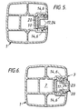
- Figure 5 shows the two nesting components 10, 20 in position in the slot 2.
- the projections 14 engage grooves 6 as before but with the limb 13 near the bottom of the slot.
- Component 20 is then inserted with projections 24 engaging grooves 17.
- the gap left between limbs 21, 22 enables an appropriately sized sign to be fitted.
- the component 20 can be reversed with its limb 23 fitting in the slot nearest the wall 3.
- the limb 23 is not shown fitting flush with the wall 3, by adjusting the positions of the grooves 17 in member 10 and/or moving the positions of the projections 24, this limb can be made to fit flush with the wall 3.
- the post 1 and components 10, 20 can be extruded in aluminium, plastics or any other suitable material. Additionally, each component may be of a different colour to match or contrast with the signs.
- Figure 7 shows the post 1 with its longitudinal slot 2.
- a portion 30 having identical cross section to component 10 is inserted into the slot 2 to rest on a further portion 31 of identical cross section to component 10 but which is inserted in the slot 2 in the configuration shown in Figure 4.
- a portion 32 of identical cross section to component 20 is inserted into postion 30 and receives a sign 33.
- a second sign 34 having a thicker cross section is retained in a portion 35 corresponding to component 10 and is spaced from the first sign 33 by a portion 36 which is similar to portion 31.
- a further spacer portion 37 fills the gap in the slot 2 between the top of the sign 34 and the top of the post 1.
- a moulded end cap 38 can then be fitted onto the top of the post to complete the assembly.
- Portions 30, 31, 35, 36 and 37 may be cut from a single extruded length of material having a cross section identical to that of component 10. Alternatively, if different coloured portions are required, they can be cut from extruded lengths appropriately coloured.
- the lengths similar to portion 32 may also be used as spacers in like fashion to that shown in Figure 7 if the post is only required to take one size of sign e.g. the sign having the smallest thickness in cross section.
- the slot 2 would be lined with a length of component 10 and portions of component 20 would be used to both hold the signs and to space signs one from another.
- each sign can be positioned at a desired height from a fixed reference e.g. the base of the post 1.
- the post 1 can be mounted on a support member (not shown) for example a pole which passes through the central cavity 7. This allows the slot 2 to be arranged in one of four orientations each space apart by 90°.
Landscapes
- Physics & Mathematics (AREA)
- General Physics & Mathematics (AREA)
- Engineering & Computer Science (AREA)
- Theoretical Computer Science (AREA)
- Road Signs Or Road Markings (AREA)
- Toys (AREA)
Applications Claiming Priority (2)
| Application Number | Priority Date | Filing Date | Title |
|---|---|---|---|
| GB888804557A GB8804557D0 (en) | 1988-02-26 | 1988-02-26 | Sign systems |
| GB8804557 | 1988-02-26 |
Publications (2)
| Publication Number | Publication Date |
|---|---|
| EP0330502A2 true EP0330502A2 (de) | 1989-08-30 |
| EP0330502A3 EP0330502A3 (de) | 1991-01-16 |
Family
ID=10632444
Family Applications (1)
| Application Number | Title | Priority Date | Filing Date |
|---|---|---|---|
| EP19890301871 Withdrawn EP0330502A3 (de) | 1988-02-26 | 1989-02-24 | Anzeigeschildanordung |
Country Status (5)
| Country | Link |
|---|---|
| US (1) | US5012603A (de) |
| EP (1) | EP0330502A3 (de) |
| JP (1) | JPH01250508A (de) |
| DK (1) | DK89389A (de) |
| GB (1) | GB8804557D0 (de) |
Cited By (1)
| Publication number | Priority date | Publication date | Assignee | Title |
|---|---|---|---|---|
| US5090145A (en) * | 1988-03-03 | 1992-02-25 | Chiang Sai M | Photo-hanging and display apparatus |
Families Citing this family (30)
| Publication number | Priority date | Publication date | Assignee | Title |
|---|---|---|---|---|
| FR2626345B1 (fr) * | 1988-01-21 | 1990-07-20 | Schouwey Jeannine | Ensemble de support polyvalent notamment pour jeux de plein air ou pour la constitution d'abris |
| US5255803A (en) * | 1991-04-03 | 1993-10-26 | Hamilton Fixture Company | Merchandising system |
| USD349302S (en) | 1992-11-17 | 1994-08-02 | Karen Wenzel-Murphy | Conical channel for retail displays |
| US5560131A (en) * | 1994-02-14 | 1996-10-01 | Burke Gibson, Inc. | Adjustable, upright display holder |
| US5584545A (en) * | 1994-07-08 | 1996-12-17 | Lavaute; Peter A. | Sneeze guard |
| DE29721936U1 (de) * | 1997-12-11 | 1998-01-29 | Nitor GmbH, 25462 Rellingen | Demonstrationswand |
| USD525721S1 (en) | 1998-01-26 | 2006-07-25 | Landes Scott D | Marking post |
| US6099203A (en) * | 1998-01-27 | 2000-08-08 | Landes; Scott D. | Marker post having a webbed triangular cross section |
| DE19951039A1 (de) * | 1999-10-22 | 2001-04-26 | Wilke Heinrich Hewi Gmbh | Präsentationssystem |
| AUPQ782300A0 (en) * | 2000-05-29 | 2000-06-22 | Telemetric Media Information Pty Ltd | Signage system |
| US20030154663A1 (en) * | 2002-02-20 | 2003-08-21 | Lars Nelson | Headstone support brace |
| KR20050101267A (ko) * | 2004-04-17 | 2005-10-21 | 삼성전자주식회사 | 평판표시장치 및 그 제조방법 |
| US7412791B2 (en) * | 2004-12-20 | 2008-08-19 | Lsi Industries, Inc. | Adjustable menu panel |
| KR100665318B1 (ko) * | 2005-06-23 | 2007-01-04 | (주) 금동강건 | 도로용 표지판 |
| US7797868B1 (en) | 2006-12-29 | 2010-09-21 | Apco Graphics, Inc. | Sign assembly having arcuate nesting component |
| US20080172915A1 (en) * | 2007-01-10 | 2008-07-24 | Brandpartners | Multi-Function Promotional Display System |
| US7661213B2 (en) * | 2008-02-14 | 2010-02-16 | Gainey Brantley K | Yard sign assembly |
| US8973645B1 (en) * | 2011-08-24 | 2015-03-10 | Carl S. Cannova | Portable wind-resistant traffic screen and related method |
| US8776414B2 (en) | 2012-02-02 | 2014-07-15 | Target Brands, Inc. | Media display assembly and merchandising system associated therewith |
| USD664599S1 (en) | 2012-02-02 | 2012-07-31 | Target Brands, Inc. | Sign holder |
| USD664600S1 (en) | 2012-02-02 | 2012-07-31 | Target Brands, Inc. | Sign holder |
| US8720090B1 (en) * | 2012-10-19 | 2014-05-13 | Inpro Corporation | Sign display system which accommodates interchangeable panels in a tamper resistant manner |
| US8782936B2 (en) | 2012-12-12 | 2014-07-22 | Target Brands, Inc. | End frame for display structure |
| US20150181729A1 (en) * | 2013-12-19 | 2015-06-25 | Peerless Industries, Inc. | Mounting fixture for a digital menu board |
| USD841095S1 (en) | 2017-07-11 | 2019-02-19 | Bryon Pickrell | Customizable signage |
| USD971329S1 (en) | 2020-02-11 | 2022-11-29 | SwanSigns, LLC | Sign frame |
| US10995916B1 (en) * | 2020-02-11 | 2021-05-04 | Matthew Murphy | Rigid and lighted flag for a vehicle |
| USD971328S1 (en) | 2020-02-11 | 2022-11-29 | SwanSigns, LLC | Sign frame |
| US12060686B2 (en) * | 2020-12-04 | 2024-08-13 | Argo Corp, Inc. | Roadway safety device |
| US20230160228A1 (en) * | 2021-11-19 | 2023-05-25 | Adam S. Laudick | Grave Marker |
Family Cites Families (8)
| Publication number | Priority date | Publication date | Assignee | Title |
|---|---|---|---|---|
| US3307280A (en) * | 1964-10-07 | 1967-03-07 | Display Corp Of America | Display apparatus |
| US3525493A (en) * | 1968-06-28 | 1970-08-25 | Best Stamp & Mfg Co | Sign wall bracket |
| GB1376126A (en) * | 1972-01-05 | 1974-12-04 | British Steel Corp | Street furniture |
| US4068398A (en) * | 1976-06-21 | 1978-01-17 | Spanjer Brothers Inc. | Knockdown sign assembly |
| GB2100044A (en) * | 1981-06-09 | 1982-12-15 | Collyer Roy Neville Spencer | Sign board |
| US4408407A (en) * | 1982-06-04 | 1983-10-11 | Architectural Signing, Inc. | Panel sign |
| GB2137795B (en) * | 1983-04-06 | 1987-04-01 | Michael Peter Gifford Hull | Sign posts |
| US4802296A (en) * | 1986-12-30 | 1989-02-07 | Signcomp, Inc. | Architectural sign system |
-
1988
- 1988-02-26 GB GB888804557A patent/GB8804557D0/en active Pending
-
1989
- 1989-02-23 JP JP1042029A patent/JPH01250508A/ja active Pending
- 1989-02-23 US US07/314,638 patent/US5012603A/en not_active Expired - Fee Related
- 1989-02-24 DK DK089389A patent/DK89389A/da not_active Application Discontinuation
- 1989-02-24 EP EP19890301871 patent/EP0330502A3/de not_active Withdrawn
Cited By (1)
| Publication number | Priority date | Publication date | Assignee | Title |
|---|---|---|---|---|
| US5090145A (en) * | 1988-03-03 | 1992-02-25 | Chiang Sai M | Photo-hanging and display apparatus |
Also Published As
| Publication number | Publication date |
|---|---|
| DK89389A (da) | 1989-08-27 |
| US5012603A (en) | 1991-05-07 |
| EP0330502A3 (de) | 1991-01-16 |
| GB8804557D0 (en) | 1988-03-30 |
| DK89389D0 (da) | 1989-02-24 |
| JPH01250508A (ja) | 1989-10-05 |
Similar Documents
| Publication | Publication Date | Title |
|---|---|---|
| US5012603A (en) | Sign systems | |
| AU7551894A (en) | Fungicidal, miticidal and arthropodicidal aminopyrimidines | |
| AU7776894A (en) | Maintaining perforation phasing | |
| AU3933793A (en) | Conveyor flight longitudinal phase adjustment assembly | |
| AU7797691A (en) | Interlocking support structures | |
| AU2068692A (en) | Curtain wall systems having improved vertical frame member | |
| AU4008593A (en) | Adjustable beam tilt antenna | |
| AU4839893A (en) | Stabilized chewable antimicrobial animal foodstuff | |
| AU7279294A (en) | Arrangement at a beam support | |
| AU669802B2 (en) | Slant plate type compressor with variable displacement mechanism | |
| AU8896691A (en) | Shroud-fin integration shelf for a helicopter empennage structure | |
| AU8707891A (en) | Slant plate type compressor with variable displacement mechanism | |
| GB2180141A (en) | Telescopic shelves | |
| AU7629496A (en) | Truncated hepatocyte growth factor variants | |
| AU5227193A (en) | Slant plate type compressor with variable displacement mechanism | |
| AU1339892A (en) | Lattice mounting structures | |
| AU1553995A (en) | Peristaltic action precision pump filler | |
| AU6023886A (en) | Back-pack with load adjustment means | |
| AU631444B2 (en) | Antimicrobial polymeric bisbiguanides | |
| AU8968091A (en) | Slant plate type compressor with variable displacement mechanism | |
| EP0213970A3 (de) | Angleichbare Tür mit erhöhter Festigkeit und Methode zur Anpassung der Abmessungen einer Tür | |
| USD335931S (en) | Window component extrusion | |
| AU1472692A (en) | Slant plate type compressor with variable displacement mechanism | |
| GB2230030A (en) | Tile mounting assembly | |
| EP0219274A3 (de) | Medizinischer Apparat mit Vorrichtung zum Montieren von Zubehören |
Legal Events
| Date | Code | Title | Description |
|---|---|---|---|
| PUAI | Public reference made under article 153(3) epc to a published international application that has entered the european phase |
Free format text: ORIGINAL CODE: 0009012 |
|
| AK | Designated contracting states |
Kind code of ref document: A2 Designated state(s): BE DE ES FR GB IT NL SE |
|
| PUAL | Search report despatched |
Free format text: ORIGINAL CODE: 0009013 |
|
| AK | Designated contracting states |
Kind code of ref document: A3 Designated state(s): BE DE ES FR GB IT NL SE |
|
| 18D | Application deemed to be withdrawn |
Effective date: 19910717 |