EP0329941A2 - Gas mask for operation in contaminated areas - Google Patents
Gas mask for operation in contaminated areas Download PDFInfo
- Publication number
- EP0329941A2 EP0329941A2 EP89100691A EP89100691A EP0329941A2 EP 0329941 A2 EP0329941 A2 EP 0329941A2 EP 89100691 A EP89100691 A EP 89100691A EP 89100691 A EP89100691 A EP 89100691A EP 0329941 A2 EP0329941 A2 EP 0329941A2
- Authority
- EP
- European Patent Office
- Prior art keywords
- facepiece
- mask
- nozzle
- opening
- outflow
- Prior art date
- Legal status (The legal status is an assumption and is not a legal conclusion. Google has not performed a legal analysis and makes no representation as to the accuracy of the status listed.)
- Granted
Links
Images


Classifications
-
- A—HUMAN NECESSITIES
- A62—LIFE-SAVING; FIRE-FIGHTING
- A62B—DEVICES, APPARATUS OR METHODS FOR LIFE-SAVING
- A62B18/00—Breathing masks or helmets, e.g. affording protection against chemical agents or for use at high altitudes or incorporating a pump or compressor for reducing the inhalation effort
- A62B18/02—Masks
-
- A—HUMAN NECESSITIES
- A62—LIFE-SAVING; FIRE-FIGHTING
- A62B—DEVICES, APPARATUS OR METHODS FOR LIFE-SAVING
- A62B18/00—Breathing masks or helmets, e.g. affording protection against chemical agents or for use at high altitudes or incorporating a pump or compressor for reducing the inhalation effort
- A62B18/08—Component parts for gas-masks or gas-helmets, e.g. windows, straps, speech transmitters, signal-devices
- A62B18/086—Adaptations for consuming refreshments without unmasking
Definitions
- the present invention refers to a gas mask for operation in contaminated areas, of the type comprising a facepiece, a nozzle tightly engaged in a lower portion of the facepiece, a half-mask situated inside said facepiece, tightly engaged on the nozzle and provided with a terminal edge intended to provide a seal around the user's nose and mouth, connection means to allow the passage of air from the interior of the facepiece to the interior of the half-mask, an inflow opening obtained in the nozzle, provided with a fitting for the assembling of a filter and communicating with the interior of the facepiece, closing valve means associated with the inflow opening, an outflow opening placing the interior of the half-mask into communication with the outer room, a single-acting outflow valve associated with the outflow opening and a phonic cap housed in the nozzle.
- the gas mask according to the invention finds a large employment in the event of natural calamities, industry accidents, and/or in any situation in which the user's survival must be ensured even in the presence in the area of highly noxious substances, be they in the form of gases, aerosols or powders.
- the gas masks intended for the above described use comprise substantially a facepiece made of impermeable material, resistant to chemical agents and associated with a harness which allows the mask to be put on the user's head so as to provide a tight seal between the edges of the facepiece and the user's face.
- the user can inhale air from the outside through an inflow opening arranged on the facepiece and provided with a threaded fitting on which is assembled a filtering element intended to decontaminate the air being inhaled.
- the air subsequently exhaled by the user is expelled from the mask through an outflow opening, also arranged on the facepiece and provided with a respective single-acting valve.
- the facepiece comprises moreover two eye-pieces or, alternatively, a single transparent screen to give the user full visibility.
- a so-called "half mask” associated to the facepiece and communicating with the outside through the outflow opening and the relative single-acting valve.
- the half mask allows the air breathed out to be directly discharged outside without filling completely the inner portions of the facepiece, in particular those corresponding to the eye-pieces. Still in order to prevent a possible clouding of the latter, it is foreseen that - in the inhalation phase - the air flow inhaled through the filter may be guided into the inner portions of the facepiece so as to skim the surfaces of the eye-pieces, to be then sucked inside the half mask through further check valves. In this way, also the clouding of the eye-pieces due to the user's perspiration is significantly reduced.
- the facepiece includes also a phonic cap, having the task of transmitting outside the user's voice to prevent an excessive toning down of the same owing to the presence of the facepiece.
- both the inflow and the outflow openings are obtained in a so-called "nozzle", tightly engaged in the lower portion of the facepiece and housing also the phonic cap. More particularly, the inflow opening is obtained in the upper part of the nozzle and flows almost directly - only by means of a short connection duct - in the interior of the facepiece, at the base of the eye-pieces and in median position between them.
- the outflow opening is instead obtained in the lower part of the nozzle and opens directly outside the mask, below the inflow opening.
- the phonic cap is situated over the inflow opening and is directed towards a chamber placed behind the connection duct and communicating with the outlet of the outflow opening downstream the corresponding single-acting valve.
- the position of the inflow opening involves a corresponding position of the filtering element which is not quite appropriate in view of a rational distribution of the masses.
- the filtering element which is situated in the upper part of the nozzle and has a considerable weight, may oppose high moments of inertia to the movements of the user's head. In this situation, a comfortable use of the mask is compromised. Further, the position of the filtering element limits downward the user's field of view.
- the position of the inflow opening limits the possibility of building up the facepiece in such as way that the eye-pieces are sufficiently near the user's eyes to permit the use of binoculars, microscopes or optical instruments in general, when the mask is worn.
- the direct connection between the inflow opening and the interior of the facepiece can originate some problems if the mask is to be used at low temperatures. In fact, in these circumstances, the inhaled air cannot be heated before skimming the user's face, giving therefore rise to a relevant uneasiness for the user.
- the entrance of air at the base of the eye-pieces, in a median portion between them, does not represent an ideal condition to obtain an "optimum" distribution of the air flow inside the facepiece. This can originate an irregular de-clouding of the eye-pieces. It is also to be noted that the air skimming the surface of the eye-pieces is not heated at all, so that it is not in the best conditions in view of an efficient de-clouding.
- the diameter of the single-acting valve must be considerably reduced, with a consequent increase of the effort to be made by the user to expel air from the mask.
- the single-acting outflow valve can take an elongated configuration, involving however high production costs and giving results, as to an efficient and reliable employment, which are anyhow worse than those obtainable by the use of circular valves of appropriate diameter.
- masks were built up, whose facepieces comprise two portions stuck together.
- a first portion which extends around the edges of the facepiece, has the task of ensuring a seal around the user's face and is therefore made of soft rubber, whilst the remaining portion of the facepiece is made of stiffer rubber.
- the main aim of the present invention is substantially that of eliminating the drawbacks of the conventional technique, and in particular that of providing a gas mask having improved characteristics of comfort, versatility and functionality, even for long periods of continuous use in unfavourable atmospheric conditions.
- a gas mask for operation in contaminated areas characterized in that the phonic cap is situated in an upper portion of the nozzle, in that the inflow opening is obtained in a lower portion of the nozzle and is communicating with the interior of the facepiece through an inflow chamber which opens bilaterally in a lower portion of the facepiece, and in that the outflow opening is obtained in the lower portion of the nozzle substantially at the level of the inflow opening and is communicating with the external atmosphere through an outflow chamber opening into a communication chamber, which opens in turn over the inflow opening at the level of the phonic cap, said inflow and outflow chambers being mutually separated by a partition extending inside the nozzle.
- the reference numeral (1) indicates in its whole a gas mask for operation in contaminated areas in accordance with the present invention.
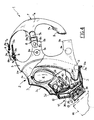
- Mask (1) comprises a facepiece (2) having a front portion (3) intended to cover entirely the face of a user and conventionally provided with eye-pieces (4).
- a sealing skirting (5) is fastened along a peripheral edge (3a) of the front portion (3); the skirting extends towards the interior of said front portion and is intended to ensure a tight seal around the user's face.
- the front portion (3) is made of semirigid rubber,having a hardness ranging between 50 and 70 Shore A, and highly resistant to chemical agents, be they in the form of gases, liquids, aerosols or powders.
- butyl rubber can be used to build up said front portion (3).
- the sealing skirting (5) is instead made of a rubber of high softness and elasticity, having preferably a hardness ranging between 40 and 70 Shore A, and a high mechanical resistance to tear.
- natural rubber can be used to build up said sealing skirting (5).
- said sealing skirting (5) is joined to the edge of the front portion (3) by means of a co-vulcanization process.
- the sealing skirting (5) forms a peripheral step (5a) intended to reinforce the area of union between the two compounds and to provide an abutment seat for the terminal edge of a hood (not illustrated) making part of a garment of the kind conventionally adopted to carry out operations in contaminated areas.
- the peripheral step (5a) is advantageously able to avoid any incidental slipping off of the hood from the user's head.
- the profile of the front portion (3), cutoff along a vertical median plane comprises a first section (3b) (as shown in FIG.4), which projects frontally with respect to the sealing skirting ((5), thus providing a wide supporting seat for said edge.
- the first section (3b) is followed by a second section (3c) which extends almost vertically, terminating with a ridge (3d). Owing to the combination between the first section (3b) and the second section (3c), the front portion (3), at the latter, is very close to the user's face.
- the eye-pieces are situated at a very short distance from the user's eyes, so that he may use optical instruments, like microscopes, binoculars and so on, even when the mask is worn, being facilitated by the absence of any protuberance external to his eyes which may interfere with the structure containing said optical instruments.
- the protruding section (3c) is entirely situated below the level of the user's pupils.
- ridge (3d) originates a pinching protrusion (6) which, when the mask is worn, results situated around the user's nose.
- This protrusion enables the user to stop his nostrils to effect a decompression if, during his work, he should be subjected to variations of atmospheric pressure.
- Facepiece (2) is moreover provided with a flexible hose (43) engaged through one side of the front portion (3) and comprising a closing member (44) arranged externally to mask (1).
- Hose (43) normally oriented along the corresponding inner side of mask (1), is able to engage - after the opening of the closing member (44) - a tubular rigid element, not illustrated, to be oriented in such a manner that its free end (43a) is brought to the level of the user's mouth. In this way the user, still with the mask on, can drink water or nourishing liquids supplied by a container associated with said tubular rigid element.
- facepiece (2) is secured to the user's face by means of a harness (7) (FIG.4), substantially composed of a cap (7a) from whose edges start braces (7b), each provided with a respective gripping element (8).
- Each gripping element (8) comprises a buckle (8a) on which is fixed the respective brace (7b), and an orientable loop (8b) comprising a hole (8c) in correspondence of which it can be removably engaged with a respective button (9) fixed to an extension (5b) of the sealing skirting (5).
- Button (9) comprises a pin-shaped element (9a) which passes through the corresponding extension (5b) and is provided with an abutment base (9b) abutting against said extension.
- a retainer (9c) shaped as a circle ring and secured to pin (9a) by forced engagement, acts against extension (5b) at the opposite side with respect to base (9b) to fasten button (9) to the sealing skirting (5).
- the front portion (3) of facepiece (2) shows in its lower part an opening through which a nozzle,indicated in its whole with (11), is tightly locked by means of a strap (10).
- Nozzle (11) comprises a front portion (12),facing towards the outside of mask (1), around which is sealed the edge of said opening.
- the lower part of said front portion (12) includes an inflow opening (13) obtained in such a way as to be substantially situated at the level of the user's mouth; the opening is provided with a threaded fitting (13a) to allow the connection of a conventional filtering device (14), illustrated in the figures but not described.
- the inflow opening (13) communicates with the interior of facepiece (2), as it will be better described here thoughinafter, and is provided with closing valve means having the task of avoiding any inhalation of external air on the user's part during the substitution of the filtering device (14).
- the closing means comprise a check valve (15), whose diaphragm (15a) can be subjected to the action of a small plate (16) fixed to the end of a stem (17) also subjected to the action of a spring (18) which operates to bring plate (16) against diaphragm (15a). Further, a rubber ring (19) is connected to stem (17), at the side opposite to plate (16), by means of spokes (19a).
- Nozzle (11) comprises moreover a rear portion (20), facing towards the inside of mask (1) and having - as shown in FIG.2 - a width smaller than that of the front portion (12).
- a half mask (22) is tightly engaged, by means of a fastening ring (21), around the rear portion (20); it is intended to exert a tight seal around the user's nose and mouth and is passed through by the flexible hose (43).
- the lower part of the rear portion (20) comprises an outflow opening (23) provided with a respective single-acting outflow valve (24).
- Said outflow valve (24) is conventionally formed by a rubber diaphragm (24a)fixed to a support (24b) and acting to seal a projection (24c) which extends around the edge of the outflow opening (23) externally to the half mask (22).
- the outflow opening (23) is originally and advantageously arranged at the level of the inflow opening (13) and is oriented in a direction substantially parallel to it.
- the axis of the outflow opening (23) is inclined with respect to the axis of the inflow opening (13) through an angle smaller than 15° and more precisely equal to 10°.
- the rear portion (20) includes a phonic cap (25) tightly engaged, through an O-ring (25a), into a housing (26) obtained over the outflow opening (23).
- the phonic cap (25) substantially comprises two half-shells (27) having respective holes (27a) distributed along concentric circumferences and made mutually fast by means of a seam (27b) extending along a peripheral edge.
- a diaphragm (28) is interposed between the two half-shells (27); during the performance of seam (27b), it is radially stretched so as to vibrate, without originating resonance phenomena, when subjected to acoustic vibrations comprised in the frequency range of the human voice.
- the phonic cap (25) kept in position by a locking nut (29) screwed in housing (26), faces towards the inside of half mask (22) and, at the opposite side, faces towards a communication opening (30) which extends through the upper portion of nozzle (11).
- the communication opening (30) opens towards the outside over the inflow opening (13), through a protection grate (31) removably connected to the front portion (12) to prevent the penetration of foreign bodies into nozzle (11).
- a separation wall (32) obtained as a single piece in the rear portion (20) and provided with a plurality of holes (33) distributed along concentric circumferences, offset with respect to the circumferences along which are distributed the above indicated holes (27a). This is done to protect diaphragm (28) from possible luminous or thermal flashes and from pressure waves.
- the rear portion (20) is made integral with the front portion (12) after the interposition of a partition (34), whose peripheral development is substantially coincident with that of said rear portion (20).
- the front portion (12) and the rear portion (20), as well as partition (34) are made of synthetic resin and are mutually connected in a tight manner by melting the material along the coupling surfaces at the points of mutual contact.
- partition (34) originates an inflow chamber (37) which communicates with the inflow opening (13) through the inlet valve (15).
- the inflow chamber (37), tightly separated from the outflow chamber (35) by virtue of partition (34), is contained between an upper wall (38) and a lower wall (39), obtained in a single piece with the front portion (12), extending along the whole width of the latter and provided with respective terminal edges (38a), (39a), tightly connected on said partition (34).
- the upper wall 38 separates in a tight manner the inflow chamber (37) from the communication chamber (30),whilst the lower wall (39) separates in a tight manner said inflow chamber from the discharge duct (36).
- the inflow chamber (37) opens bilaterally into the lower part of facepiece(2), in the space comprised between the inner walls of the latter and the outer walls of half mask (22).
- the depression originated inside half mask (22) by the user's breath causes the intake of air from the outside through the filtering element (14).
- the air penetrating into nozzle (11) through the inflow opening (13) strikes wall (34d) of the partition in the zone opposite to that from which the partition is skimmed by the air exhaled by the user.
- the air conveyed into the inflow chamber (37) would be advantageously ready to receive heat from the wall of partition (34), heated by the exhaled air. Subsequently, the inhaled air is conveyed into the free space between facepiece (2) and half mask (22), as indicated by arrow A in FIG.2.
- half mask (22) can be provided, at symmetrically opposite parts, with two guiding baffles (40), only one of which is shown in FIG.4, which are positioned over the inflow chamber (37), project towards facepiece (2) and extend symmetrically along said half mask.
- baffles prevents the air conveyed to the base of facepiece (2) from penetrating immediately into the upper portions of the latter.
- the air outflowing bilaterally from the inflow chamber (37) is guided along the whole lower portion of the facepiece, to be then conveyed to the upper portion of the same so as to flow laterally to eye-pieces (4) and to move towards the center of facepiece (2) with a centripetal motion.
- connection means represented by single-acting valves (41) conventionally provided on the latter and intended to avoid that, in the next exhalation phase, the exhaled air may fill the free space between half mask and facepiece.
- the depression originated inside half mask (22) actuates the outflow valve (24) so as to create a perfect adherence of diaphragm (24a) on edge (24c). In this way the air present in the outflow chamber (35), communicating with the external atmosphere, is prevented from being sucked into half mask (22).
- the pressure produced in half mask (22) causes the closure of the single acting valves (41) and the opening of the outflow valve (24) further to the detachment of diaphragm (24a) from edge (24c).
- the air outflowing from the outflow opening (23) fills the outflow chamber (35) and transfers heat to the wall of partition (34).
- the condensate consequently deposited on partition (34) is released through the discharge duct (36).
- partition (34) may be provided with a rib (42) extending vertically along a direction containing the axis of the inflow valve (24) and having a terminal edge (42a) situated in proximity of diaphragm (24a). Rib (42) reduces the opening of valve (24) to avoid that a large part of the inhaled air may reach the communication opening (30) without skimming the wall of partition (34).
- the exhaled air flowing along the outflow chamber (35), passes also on the separation wall (32), cleaning it from contaminating agents which may have deposited on the same.
- the exhaled air is discharged outside through the communication opening (30) and the protection grate (31), as indicated by arrow B in FIG.1.
- the present invention is able to achieve the purposes it aimed at.
- the mask forming its subject matter shows over the prior art improved characteristics as regards functionality, practicity and comfort.
- the position of the filter in the lower portion of the nozzle avoids the inconvenience represented by the limitation of the efficiency of the phonic cap, which is instead ascertained.
- the sounds transmitted by the phonic cap may reach directly the external atmosphere through the connection chamber (30). This has made possible a significant reduction in the size of the phonic cap, to the advantage of the single-acting outflow valve, which is provided with a circular diaphragm of comparatively large diameter.
- the original structure of the nozzle prevents the inhaled air from flowing directly into the highest portions of the facepiece. This brings to a pre-heating of the inhaled air, which results in turn in an improved de-clouding action of the eye-pieces and in the elimination of any risk of freezing for the operator's face.
- Another important advantage of the present invention is due to the fact that the exhaled air is discharged in the external atmosphere without skimming the surface of the filtering element. In this way the formation of ice on the latter, in the presence of low temperatures, can be prevented.
- the adoption of two different rubber compounds, co-vulcanixed to obtain the facepiece gives rise to a very light and resistant structure of the mask in its whole, without anyhow affecting its functional characteristics.
- the presence of the peripheral step (5a) and of the supporting seat formed by the first section (3b) ensures the correct positioning of the hood of the protective garment on the mask.
Landscapes
- Health & Medical Sciences (AREA)
- Pulmonology (AREA)
- General Health & Medical Sciences (AREA)
- Business, Economics & Management (AREA)
- Emergency Management (AREA)
- Life Sciences & Earth Sciences (AREA)
- Zoology (AREA)
- Respiratory Apparatuses And Protective Means (AREA)
- Preparing Plates And Mask In Photomechanical Process (AREA)
- Materials For Medical Uses (AREA)
- Cold Cathode And The Manufacture (AREA)
- Solid-Sorbent Or Filter-Aiding Compositions (AREA)
Abstract
An inflow opening (13) and an outflow opening (23), substantially coaxial, are obtained in the lower portion of the nozzle; the first places into communication the external atmosphere with the interior of the facepiece and the second, respectively, with the interior of the half mask through an inflow chamber (37),and an outflow chamber (35), separated by a partition (34).
The inflow chamber communicates bilaterally with a space comprised between the half mask and the facepiece. The outflow chamber communicates with the outside, over the inflow opening, and in front of a phonic cap (25) assembled in the upper part of the nozzle.
Description
- The present invention refers to a gas mask for operation in contaminated areas, of the type comprising a facepiece, a nozzle tightly engaged in a lower portion of the facepiece, a half-mask situated inside said facepiece, tightly engaged on the nozzle and provided with a terminal edge intended to provide a seal around the user's nose and mouth, connection means to allow the passage of air from the interior of the facepiece to the interior of the half-mask, an inflow opening obtained in the nozzle, provided with a fitting for the assembling of a filter and communicating with the interior of the facepiece, closing valve means associated with the inflow opening, an outflow opening placing the interior of the half-mask into communication with the outer room, a single-acting outflow valve associated with the outflow opening and a phonic cap housed in the nozzle.
- The gas mask according to the invention finds a large employment in the event of natural calamities, industry accidents, and/or in any situation in which the user's survival must be ensured even in the presence in the area of highly noxious substances, be they in the form of gases, aerosols or powders.
- As known, the gas masks intended for the above described use comprise substantially a facepiece made of impermeable material, resistant to chemical agents and associated with a harness which allows the mask to be put on the user's head so as to provide a tight seal between the edges of the facepiece and the user's face.
- Once the mask is put on, the user can inhale air from the outside through an inflow opening arranged on the facepiece and provided with a threaded fitting on which is assembled a filtering element intended to decontaminate the air being inhaled. The air subsequently exhaled by the user is expelled from the mask through an outflow opening, also arranged on the facepiece and provided with a respective single-acting valve.
- The facepiece comprises moreover two eye-pieces or, alternatively, a single transparent screen to give the user full visibility. To prevent the air breathed out from causing clouding of the eye-pieces, in many cases provision is made of a so-called "half mask", associated to the facepiece and communicating with the outside through the outflow opening and the relative single-acting valve.
- The half mask allows the air breathed out to be directly discharged outside without filling completely the inner portions of the facepiece, in particular those corresponding to the eye-pieces. Still in order to prevent a possible clouding of the latter, it is foreseen that - in the inhalation phase - the air flow inhaled through the filter may be guided into the inner portions of the facepiece so as to skim the surfaces of the eye-pieces, to be then sucked inside the half mask through further check valves. In this way, also the clouding of the eye-pieces due to the user's perspiration is significantly reduced.
- Generally, the facepiece includes also a phonic cap, having the task of transmitting outside the user's voice to prevent an excessive toning down of the same owing to the presence of the facepiece.
- In the masks of modern design, both the inflow and the outflow openings are obtained in a so-called "nozzle", tightly engaged in the lower portion of the facepiece and housing also the phonic cap.
More particularly, the inflow opening is obtained in the upper part of the nozzle and flows almost directly - only by means of a short connection duct - in the interior of the facepiece, at the base of the eye-pieces and in median position between them. - The outflow opening is instead obtained in the lower part of the nozzle and opens directly outside the mask, below the inflow opening. The phonic cap is situated over the inflow opening and is directed towards a chamber placed behind the connection duct and communicating with the outlet of the outflow opening downstream the corresponding single-acting valve.
- It was noted that the arrangement of the above described elements originates some inconveniences as regards the practical and functional employment of the gas mask. At first, it can be seen that the position of the inflow opening involves a corresponding position of the filtering element which is not quite appropriate in view of a rational distribution of the masses.
In fact the filtering element, which is situated in the upper part of the nozzle and has a considerable weight, may oppose high moments of inertia to the movements of the user's head. In this situation, a comfortable use of the mask is compromised. Further, the position of the filtering element limits downward the user's field of view. - It was also noted that the position of the inflow opening limits the possibility of building up the facepiece in such as way that the eye-pieces are sufficiently near the user's eyes to permit the use of binoculars, microscopes or optical instruments in general, when the mask is worn.
- Moreover, the direct connection between the inflow opening and the interior of the facepiece can originate some problems if the mask is to be used at low temperatures. In fact, in these circumstances, the inhaled air cannot be heated before skimming the user's face, giving therefore rise to a relevant uneasiness for the user.
- Furthermore, the entrance of air at the base of the eye-pieces, in a median portion between them, does not represent an ideal condition to obtain an "optimum" distribution of the air flow inside the facepiece. This can originate an irregular de-clouding of the eye-pieces. It is also to be noted that the air skimming the surface of the eye-pieces is not heated at all, so that it is not in the best conditions in view of an efficient de-clouding.
- Another disadvantage of the prior art is that the air outcoming from the outflow opening tends to skim the surfaces of the filtering element. At low temperatures and after a prolonged use of the mask, this circumstance can originate the formation of a certain amount of ice on the filtering element, due to the freezing of the water molecules present in the exhaled air. The consequent increase in the weight of the filtering element compromises therefore the comfort - and above all the safety - of the mask.
- The position of the phonic cap, situated behind the inflow opening, affects significantly a good transmission of the user's voice towards the mask outside. In fact the voice is compelled to reach the outflow opening and to come out below the filtering element. To compensate for the poor quality of this transmission, it is at present necessary to provide phonic caps of big dimensions, to the detriment of the space available for the single-acting valve associated with the outflow opening.
- In this situation, the diameter of the single-acting valve must be considerably reduced, with a consequent increase of the effort to be made by the user to expel air from the mask. Alternatively, the single-acting outflow valve can take an elongated configuration, involving however high production costs and giving results, as to an efficient and reliable employment, which are anyhow worse than those obtainable by the use of circular valves of appropriate diameter.
- In the production of masks according to the conventional technique, some problems arise from the contrasting needs of providing facepieces which must be sufficiently stiff to prevent excessive oscillations of the unit formed by the nozzle and the filtering element and, at the same time, must be sufficiently soft and elastic to ensure a perfect sealing action around the user's face.
- Generally, these needs are satisfied by making the facepiece with soft rubber layers having a reduced thickness along the edges to be sealed around the user's face and a greater thickness, to provide additional stiffness, in the front portions of the facepiece. These expedients, however, originate a relevant increase in the mask weight in its whole and therefore may compromise its comfort, in particular in view of a prolonged use.
- Attempt to eliminate such disadvantages have led to the production of facepieces whose front portions are reinforced with fabric layers embedded in the rubber. Anyhow, this requires long and complicate procedures, not convenient for a volume production.
- Also, masks were built up, whose facepieces comprise two portions stuck together. A first portion, which extends around the edges of the facepiece, has the task of ensuring a seal around the user's face and is therefore made of soft rubber, whilst the remaining portion of the facepiece is made of stiffer rubber. This solution involves problems regarding reliability of use, since it may easily happen for the mask to be employed in atmospheres containing solvents able to attack chemically the bonding agents used to join the two portions forming the facepiece.
- The main aim of the present invention is substantially that of eliminating the drawbacks of the conventional technique, and in particular that of providing a gas mask having improved characteristics of comfort, versatility and functionality, even for long periods of continuous use in unfavourable atmospheric conditions.
- This and other purposes, which will be more clearly apparent from the following description, are substantially achieved by means of a gas mask for operation in contaminated areas, characterized in that the phonic cap is situated in an upper portion of the nozzle, in that the inflow opening is obtained in a lower portion of the nozzle and is communicating with the interior of the facepiece through an inflow chamber which opens bilaterally in a lower portion of the facepiece, and in that the outflow opening is obtained in the lower portion of the nozzle substantially at the level of the inflow opening and is communicating with the external atmosphere through an outflow chamber opening into a communication chamber, which opens in turn over the inflow opening at the level of the phonic cap, said inflow and outflow chambers being mutually separated by a partition extending inside the nozzle.
- Further characteristics and advantages of the disclosure will clearly appear from the detailed description of a preferred but not exclusive embodiment of a gas mask for operation in contaminated areas, in accordance with the present invention, made herebelow with reference to the attached drawings given only by way of non-limiting example, in which :
- FIGURE 1 - represents, in broken longitudinal section, the nozzle of the mask according to the present invention;
- FIGURE 2 - represents the nozzle cutaway along line II-II of FIG.1;
- FIGURE 3 - is a front view of the mask, and
- FIGURE 4 - is a broken section of the mask according to the invention, taken along line IV-IV of FIG.3.
- With particular reference to FIG.3 and FIG.4, the reference numeral (1) indicates in its whole a gas mask for operation in contaminated areas in accordance with the present invention.
- Mask (1) comprises a facepiece (2) having a front portion (3) intended to cover entirely the face of a user and conventionally provided with eye-pieces (4). A sealing skirting (5) is fastened along a peripheral edge (3a) of the front portion (3); the skirting extends towards the interior of said front portion and is intended to ensure a tight seal around the user's face.
- The front portion (3) is made of semirigid rubber,having a hardness ranging between 50 and 70 Shore A, and highly resistant to chemical agents, be they in the form of gases, liquids, aerosols or powders. For instance, butyl rubber can be used to build up said front portion (3).
- The sealing skirting (5) is instead made of a rubber of high softness and elasticity, having preferably a hardness ranging between 40 and 70 Shore A, and a high mechanical resistance to tear. For instance, natural rubber can be used to build up said sealing skirting (5).
- In an original and advantageous manner, said sealing skirting (5) is joined to the edge of the front portion (3) by means of a co-vulcanization process.
- At edge (3a), the sealing skirting (5) forms a peripheral step (5a) intended to reinforce the area of union between the two compounds and to provide an abutment seat for the terminal edge of a hood (not illustrated) making part of a garment of the kind conventionally adopted to carry out operations in contaminated areas. The peripheral step (5a) is advantageously able to avoid any incidental slipping off of the hood from the user's head.
- Further, to prevent that the hood edge may unduly cover the eyepieces (4), the profile of the front portion (3), cutoff along a vertical median plane, comprises a first section (3b) (as shown in FIG.4), which projects frontally with respect to the sealing skirting ((5), thus providing a wide supporting seat for said edge.
- Conveniently, the first section (3b) is followed by a second section (3c) which extends almost vertically, terminating with a ridge (3d). Owing to the combination between the first section (3b) and the second section (3c), the front portion (3), at the latter, is very close to the user's face.
- Therefore, the eye-pieces are situated at a very short distance from the user's eyes, so that he may use optical instruments, like microscopes, binoculars and so on, even when the mask is worn, being facilitated by the absence of any protuberance external to his eyes which may interfere with the structure containing said optical instruments. For this purpose the protruding section (3c) is entirely situated below the level of the user's pupils.
- As visible in FIG.3, ridge (3d) originates a pinching protrusion (6) which, when the mask is worn, results situated around the user's nose. This protrusion enables the user to stop his nostrils to effect a decompression if, during his work, he should be subjected to variations of atmospheric pressure.
- Facepiece (2) is moreover provided with a flexible hose (43) engaged through one side of the front portion (3) and comprising a closing member (44) arranged externally to mask (1). Hose (43), normally oriented along the corresponding inner side of mask (1), is able to engage - after the opening of the closing member (44) - a tubular rigid element, not illustrated, to be oriented in such a manner that its free end (43a) is brought to the level of the user's mouth. In this way the user, still with the mask on, can drink water or nourishing liquids supplied by a container associated with said tubular rigid element.
- In a conventional manner, facepiece (2) is secured to the user's face by means of a harness (7) (FIG.4), substantially composed of a cap (7a) from whose edges start braces (7b), each provided with a respective gripping element (8). Each gripping element (8) comprises a buckle (8a) on which is fixed the respective brace (7b), and an orientable loop (8b) comprising a hole (8c) in correspondence of which it can be removably engaged with a respective button (9) fixed to an extension (5b) of the sealing skirting (5).
- Button (9) comprises a pin-shaped element (9a) which passes through the corresponding extension (5b) and is provided with an abutment base (9b) abutting against said extension. A retainer (9c), shaped as a circle ring and secured to pin (9a) by forced engagement, acts against extension (5b) at the opposite side with respect to base (9b) to fasten button (9) to the sealing skirting (5).
- The front portion (3) of facepiece (2) shows in its lower part an opening through which a nozzle,indicated in its whole with (11), is tightly locked by means of a strap (10). Nozzle (11) comprises a front portion (12),facing towards the outside of mask (1), around which is sealed the edge of said opening.
- The lower part of said front portion (12) includes an inflow opening (13) obtained in such a way as to be substantially situated at the level of the user's mouth; the opening is provided with a threaded fitting (13a) to allow the connection of a conventional filtering device (14), illustrated in the figures but not described.
- The inflow opening (13) communicates with the interior of facepiece (2), as it will be better described hereinafter, and is provided with closing valve means having the task of avoiding any inhalation of external air on the user's part during the substitution of the filtering device (14).
- The closing means comprise a check valve (15), whose diaphragm (15a) can be subjected to the action of a small plate (16) fixed to the end of a stem (17) also subjected to the action of a spring (18) which operates to bring plate (16) against diaphragm (15a). Further, a rubber ring (19) is connected to stem (17), at the side opposite to plate (16), by means of spokes (19a).
- When the filtering device (14) is correctly assembled, ring (19) is pushed in the direction of valve (15) according to what is illustrated in FIG.1. In this situation, plate (16) is spaced apart from diaphragm (15a), which is able to carry out its action directed to open or to close valve (15).
- On the contrary, when the filtering device (14) is disengaged from mask (1), the action of spring (18) causes the detachment of ring (19) from valve (15) and brings plate (16) into contact with diaphragm (15a). Consequently, said diaphragm (15a) is continuously pressed against a corresponding sealing seat (15b), so as to prevent the inhalation of air inside mask (1).
- Nozzle (11) comprises moreover a rear portion (20), facing towards the inside of mask (1) and having - as shown in FIG.2 - a width smaller than that of the front portion (12). A half mask (22) is tightly engaged, by means of a fastening ring (21), around the rear portion (20); it is intended to exert a tight seal around the user's nose and mouth and is passed through by the flexible hose (43).
- The lower part of the rear portion (20) comprises an outflow opening (23) provided with a respective single-acting outflow valve (24). Said outflow valve (24) is conventionally formed by a rubber diaphragm (24a)fixed to a support (24b) and acting to seal a projection (24c) which extends around the edge of the outflow opening (23) externally to the half mask (22). As clearly visible in FIGS.1 and 2, the outflow opening (23) is originally and advantageously arranged at the level of the inflow opening (13) and is oriented in a direction substantially parallel to it.
- In the illustrated example, the axis of the outflow opening (23) is inclined with respect to the axis of the inflow opening (13) through an angle smaller than 15° and more precisely equal to 10°.
- Further, the rear portion (20) includes a phonic cap (25) tightly engaged, through an O-ring (25a), into a housing (26) obtained over the outflow opening (23). In a conventional way already known, the phonic cap (25) substantially comprises two half-shells (27) having respective holes (27a) distributed along concentric circumferences and made mutually fast by means of a seam (27b) extending along a peripheral edge.
- A diaphragm (28) is interposed between the two half-shells (27); during the performance of seam (27b), it is radially stretched so as to vibrate, without originating resonance phenomena, when subjected to acoustic vibrations comprised in the frequency range of the human voice. The phonic cap (25), kept in position by a locking nut (29) screwed in housing (26), faces towards the inside of half mask (22) and, at the opposite side, faces towards a communication opening (30) which extends through the upper portion of nozzle (11). The communication opening (30) opens towards the outside over the inflow opening (13), through a protection grate (31) removably connected to the front portion (12) to prevent the penetration of foreign bodies into nozzle (11).
- Advantageously, between the phonic cap (25) and the communication opening (30), provision is made of a separation wall (32) obtained as a single piece in the rear portion (20) and provided with a plurality of holes (33) distributed along concentric circumferences, offset with respect to the circumferences along which are distributed the above indicated holes (27a). This is done to protect diaphragm (28) from possible luminous or thermal flashes and from pressure waves.
- The rear portion (20) is made integral with the front portion (12) after the interposition of a partition (34), whose peripheral development is substantially coincident with that of said rear portion (20). In a preferred embodiment, the front portion (12) and the rear portion (20), as well as partition (34), are made of synthetic resin and are mutually connected in a tight manner by melting the material along the coupling surfaces at the points of mutual contact.
- Partition (34), with respect to the rear portion (20), originates an outflow chamber (35) which communicates with the interior of half mask (22) through the outflow opening (23) and with the external atmosphere through the communication opening (30). Further, at the base of nozzle (11), the outflow chamber (35) extends into a discharge duct (36) which passes through partition (34) and the front portion (12) and outcomes from the latter below the inflow opening (13).
- With respect to the front portion (12), the presence of partition (34) originates an inflow chamber (37) which communicates with the inflow opening (13) through the inlet valve (15). The inflow chamber (37), tightly separated from the outflow chamber (35) by virtue of partition (34), is contained between an upper wall (38) and a lower wall (39), obtained in a single piece with the front portion (12), extending along the whole width of the latter and provided with respective terminal edges (38a), (39a), tightly connected on said partition (34). The
upper wall 38 separates in a tight manner the inflow chamber (37) from the communication chamber (30),whilst the lower wall (39) separates in a tight manner said inflow chamber from the discharge duct (36). - As it can be seen in FIG.2, as the width of the rear portion (20) and that of partition (34) are smaller than the width of the front portion (12), the inflow chamber (37) opens bilaterally into the lower part of facepiece(2), in the space comprised between the inner walls of the latter and the outer walls of half mask (22).
- During the normal use of the gas mask (1), the depression originated inside half mask (22) by the user's breath causes the intake of air from the outside through the filtering element (14). The air penetrating into nozzle (11) through the inflow opening (13) strikes wall (34d) of the partition in the zone opposite to that from which the partition is skimmed by the air exhaled by the user.
- When the mask is to be used at low temperatures, the air conveyed into the inflow chamber (37) would be advantageously ready to receive heat from the wall of partition (34), heated by the exhaled air. Subsequently, the inhaled air is conveyed into the free space between facepiece (2) and half mask (22), as indicated by arrow A in FIG.2.
- Conveniently, half mask (22) can be provided, at symmetrically opposite parts, with two guiding baffles (40), only one of which is shown in FIG.4, which are positioned over the inflow chamber (37), project towards facepiece (2) and extend symmetrically along said half mask. The presence of said baffles prevents the air conveyed to the base of facepiece (2) from penetrating immediately into the upper portions of the latter.
- In fact, the air outflowing bilaterally from the inflow chamber (37) is guided along the whole lower portion of the facepiece, to be then conveyed to the upper portion of the same so as to flow laterally to eye-pieces (4) and to move towards the center of facepiece (2) with a centripetal motion.
- In this situation, still with reference to the employment of the mask at low temperatures, the air would be further heated before reaching the upper part of the facepiece, so as not to ingenerate any risk of freezing for the user's face and to afford the optimum characteristics necessary for a good de-clouding of eye-pieces (24).
- Subsequently, air is conveyed into half mask (22)through connection means represented by single-acting valves (41) conventionally provided on the latter and intended to avoid that, in the next exhalation phase, the exhaled air may fill the free space between half mask and facepiece.
- Still with reference to the inhalation phase, the depression originated inside half mask (22) actuates the outflow valve (24) so as to create a perfect adherence of diaphragm (24a) on edge (24c). In this way the air present in the outflow chamber (35), communicating with the external atmosphere, is prevented from being sucked into half mask (22).
- During the exhalation phase, the pressure produced in half mask (22) causes the closure of the single acting valves (41) and the opening of the outflow valve (24) further to the detachment of diaphragm (24a) from edge (24c). The air outflowing from the outflow opening (23) fills the outflow chamber (35) and transfers heat to the wall of partition (34). The condensate consequently deposited on partition (34) is released through the discharge duct (36).
- Conveniently, partition (34) may be provided with a rib (42) extending vertically along a direction containing the axis of the inflow valve (24) and having a terminal edge (42a) situated in proximity of diaphragm (24a). Rib (42) reduces the opening of valve (24) to avoid that a large part of the inhaled air may reach the communication opening (30) without skimming the wall of partition (34).
- The exhaled air, flowing along the outflow chamber (35), passes also on the separation wall (32), cleaning it from contaminating agents which may have deposited on the same. At last, the exhaled air is discharged outside through the communication opening (30) and the protection grate (31), as indicated by arrow B in FIG.1.
- The present invention is able to achieve the purposes it aimed at. In fact, the mask forming its subject matter shows over the prior art improved characteristics as regards functionality, practicity and comfort.
- In particular, the arrangements adopted in respect of nozzle (11), in the lower portion of which is situated the filtering element, have led to a better distribution of the masses and have eliminated the disadvantages due - in the conventional masks of the above type - to the downward limitation of the visual field.
- Further, the position of the filter in the lower portion of the nozzle avoids the inconvenience represented by the limitation of the efficiency of the phonic cap, which is instead ascertained. In fact, in the mask according to the invention, the sounds transmitted by the phonic cap may reach directly the external atmosphere through the connection chamber (30). This has made possible a significant reduction in the size of the phonic cap, to the advantage of the single-acting outflow valve, which is provided with a circular diaphragm of comparatively large diameter.
- Further, the original structure of the nozzle prevents the inhaled air from flowing directly into the highest portions of the facepiece. This brings to a pre-heating of the inhaled air, which results in turn in an improved de-clouding action of the eye-pieces and in the elimination of any risk of freezing for the operator's face.
- These effects are incremented by the particular construction of the facepiece and of the half mask, which appear able to induce the air to effect a long centripetal travel before reaching the eye-pieces. In particular, the structure of the outer portion of the facepiece permits to situate the eye-pieces in close proximity to the user's eyes, so that he is enabled to use optical instruments.
- Another important advantage of the present invention is due to the fact that the exhaled air is discharged in the external atmosphere without skimming the surface of the filtering element. In this way the formation of ice on the latter, in the presence of low temperatures, can be prevented.
- Further, the adoption of two different rubber compounds, co-vulcanixed to obtain the facepiece, gives rise to a very light and resistant structure of the mask in its whole, without anyhow affecting its functional characteristics. Moreover, the presence of the peripheral step (5a) and of the supporting seat formed by the first section (3b) ensures the correct positioning of the hood of the protective garment on the mask.
- It is understood that the present invention comprises any possible modification or alternative embodiment included in the scope of the inventive prionciple on which it is grounded.
Claims (15)
Priority Applications (1)
| Application Number | Priority Date | Filing Date | Title |
|---|---|---|---|
| AT89100691T ATE87839T1 (en) | 1988-02-26 | 1989-01-17 | RESPIRATOR FOR POLLUTED ENVIRONMENTS. |
Applications Claiming Priority (2)
| Application Number | Priority Date | Filing Date | Title |
|---|---|---|---|
| IT1955888 | 1988-02-26 | ||
| IT8819558A IT1216459B (en) | 1988-02-26 | 1988-02-26 | PROTECTIVE MASK FOR OPERATIONAL INTERVENTIONS IN CONTAMINATED ENVIRONMENTS. |
Publications (3)
| Publication Number | Publication Date |
|---|---|
| EP0329941A2 true EP0329941A2 (en) | 1989-08-30 |
| EP0329941A3 EP0329941A3 (en) | 1990-06-13 |
| EP0329941B1 EP0329941B1 (en) | 1993-04-07 |
Family
ID=11159047
Family Applications (1)
| Application Number | Title | Priority Date | Filing Date |
|---|---|---|---|
| EP89100691A Expired - Lifetime EP0329941B1 (en) | 1988-02-26 | 1989-01-17 | Gas mask for operation in contaminated areas |
Country Status (7)
| Country | Link |
|---|---|
| US (1) | US4961420A (en) |
| EP (1) | EP0329941B1 (en) |
| AT (1) | ATE87839T1 (en) |
| DE (1) | DE68905843D1 (en) |
| FI (1) | FI87144C (en) |
| IT (1) | IT1216459B (en) |
| NO (1) | NO171767C (en) |
Cited By (6)
| Publication number | Priority date | Publication date | Assignee | Title |
|---|---|---|---|---|
| DE4220780C1 (en) * | 1992-06-25 | 1993-09-23 | Draegerwerk Ag, 23558 Luebeck, De | |
| US6338341B1 (en) | 1998-11-06 | 2002-01-15 | DRäGER SICHERHEITSTECHNIK GMBH | Protective breathing mask |
| US7120940B2 (en) * | 2002-03-12 | 2006-10-17 | Bombardier Recreational Products Inc. | Breathing mask adjuster |
| WO2008136021A1 (en) * | 2007-05-02 | 2008-11-13 | Officine Meccaniche Galli S.R.L. | Inlet connector of an m90 nbc face mask provided with means for obtaining low respiratory resistance values both during inhaling and exhaling phases |
| US7762256B2 (en) | 2001-10-12 | 2010-07-27 | Euromaski Oy | Protective device |
| WO2012095061A1 (en) * | 2011-01-12 | 2012-07-19 | Clean - Air S.R.O. | Self-acting closure of filter-ventilating unit |
Families Citing this family (49)
| Publication number | Priority date | Publication date | Assignee | Title |
|---|---|---|---|---|
| US5753698A (en) * | 1986-05-13 | 1998-05-19 | Redox Pharmaceutical Corporation | Method for treating cyanide poisoning |
| US5138666A (en) * | 1987-12-18 | 1992-08-11 | Actron Manufacturing Company | Voice transmission system |
| US5371804A (en) * | 1987-12-18 | 1994-12-06 | Actron Manufacturing Company | Voice transmission system |
| USH1361H (en) * | 1992-05-06 | 1994-10-04 | The United States Of America As Represented By The Secretary Of The Army | Softshell protective mask |
| US5428688A (en) * | 1993-03-29 | 1995-06-27 | Audiopack Sounds Systems | Voice transmission system with remote microphone |
| US5463693A (en) * | 1993-11-10 | 1995-10-31 | Audiopack Sound Systems Inc. | Voice amplification adapter assembly for face mask |
| US5990793A (en) * | 1994-09-02 | 1999-11-23 | Safety Tech Industries, Inc. | Firefighters integrated communication and safety system |
| US6121881A (en) * | 1994-09-02 | 2000-09-19 | Safety Tech Industries, Inc. | Protective mask communication devices and systems for use in hazardous environments |
| US5724965A (en) * | 1995-06-06 | 1998-03-10 | Respironics Inc. | Nasal mask |
| USD378610S (en) * | 1995-10-27 | 1997-03-25 | Minnesota Mining And Manufacturing Company | Full face respirator |
| USD409744S (en) * | 1997-03-05 | 1999-05-11 | Minnesota Mining And Manufacturing Company | Full face respirator lens |
| US5895537A (en) * | 1997-10-09 | 1999-04-20 | Campbell; Richard G. | Sonic welded gas mask and process |
| USD426298S (en) * | 1998-07-20 | 2000-06-06 | 3M Innovative Properties Company | Full-face respirator lens |
| DE19845572C2 (en) * | 1998-10-02 | 2002-06-06 | Draeger Safety Ag & Co Kgaa | Speech transmitter for a respirator |
| FR2786107B1 (en) * | 1998-11-25 | 2001-02-16 | Sextant Avionique | OXYGEN INHALER MASK WITH SOUND TAKING DEVICE |
| EP1274486A2 (en) | 2000-04-17 | 2003-01-15 | Scott Technologies, Inc. | Respiratory mask and service module |
| CA2405510C (en) * | 2000-04-18 | 2008-10-07 | Avon Rubber & Plastics, Inc. | Self-sealing filter connection and gas mask and filter assembly incorporating the same |
| CN1285392C (en) * | 2001-05-11 | 2006-11-22 | 矿井安全装置公司 | Respirator facepieces |
| DE10159219B4 (en) * | 2001-11-27 | 2005-09-29 | Msa Auer Gmbh | Respiratory mask for a compressed air breathing apparatus |
| US6681765B2 (en) | 2001-12-18 | 2004-01-27 | Sheree H. Wen | Antiviral and antibacterial respirator mask |
| US6701925B1 (en) | 2002-04-11 | 2004-03-09 | Todd A. Resnick | Protective hood respirator |
| GB0222497D0 (en) * | 2002-09-27 | 2002-11-06 | Secr Defence | Respirator |
| US7198079B2 (en) * | 2003-09-09 | 2007-04-03 | Tvi Corporation | Liquid delivery system of gas mask |
| US7044127B1 (en) * | 2003-09-11 | 2006-05-16 | Fernandez Decastro Aurora L | Multipurpose mask |
| US8584676B2 (en) * | 2003-11-19 | 2013-11-19 | Immediate Response Technologies | Breath responsive filter blower respirator system |
| US7273052B2 (en) * | 2003-12-11 | 2007-09-25 | Tvi Corporation | Pneumatic sealing system for protection masks |
| US7690379B2 (en) * | 2004-06-01 | 2010-04-06 | Branch, Banking and Trust Company | Pressure indicator for positive pressure protection masks |
| US7469699B2 (en) * | 2004-09-03 | 2008-12-30 | Tvi Corporation | Thin profile air purifying blower unit and filter cartridges, and method of use |
| US8042540B2 (en) * | 2004-10-15 | 2011-10-25 | Southmedic Incorporated | Patient oxygen delivery mask |
| US7458390B2 (en) * | 2005-12-21 | 2008-12-02 | Tvi Corporation | Breath controlled air inlet for blower |
| US8613113B1 (en) * | 2009-02-25 | 2013-12-24 | Todd A. Resnick | Compact protective hood with vulcanized neck dam interface |
| US8590533B2 (en) * | 2010-10-14 | 2013-11-26 | Casey Danford | Adjustable inhalation resistence exercise device |
| US9162088B2 (en) | 2012-10-25 | 2015-10-20 | Honeywell International Inc. | Method of assembly and disassembly of abrasive blast respirator |
| US9192796B2 (en) | 2012-10-25 | 2015-11-24 | Honeywell International Inc. | Method of donning and testing abrasive blast respirator |
| US9192793B2 (en) * | 2012-10-25 | 2015-11-24 | Honeywell International Inc. | Abrasive blast respirator |
| US9192794B2 (en) | 2012-10-25 | 2015-11-24 | Honeywell International Inc. | Noise reduction system for supplied air respirator |
| EP2805749B1 (en) * | 2013-05-22 | 2019-12-25 | Moldex-Metric AG & Co. KG | Breathing mask |
| US10105557B1 (en) * | 2013-11-06 | 2018-10-23 | The United States Of America As Represented By The Secretary Of The Army | Valve/connection system to prevent downstream contamination from an upstream source while replacing filters |
| USD767754S1 (en) | 2015-11-02 | 2016-09-27 | Trainingmask, Llc | Resistance and filtration breathing device |
| USD765237S1 (en) | 2015-11-04 | 2016-08-30 | Trainingmask, Llc | Resistance breathing device |
| US9579540B1 (en) | 2016-01-06 | 2017-02-28 | Trainingmask, L.L.C. | Resistance breathing device |
| USD811581S1 (en) | 2016-03-03 | 2018-02-27 | Trainingmask Llc | Resistance breathing device |
| US9707444B1 (en) | 2016-03-22 | 2017-07-18 | Trainingmask Llc | Resistance breathing device |
| RU2661272C2 (en) | 2016-09-09 | 2018-07-13 | Трейнингмаск Л.Л.К. | Device for breathing with resistance |
| USD820974S1 (en) | 2016-09-30 | 2018-06-19 | TrainingMask L.L.C. | Resistance breathing device |
| US10322312B1 (en) | 2018-06-01 | 2019-06-18 | TrainingMask L.L.C. | Resistance and filtration breathing device |
| USD952130S1 (en) | 2019-09-30 | 2022-05-17 | TrainingMask L.L.C. | Mask insert |
| US11219255B2 (en) | 2020-04-08 | 2022-01-11 | Terry Earl Brady | Self-contained, mobile breathing apparatus or appliance that supplies pathogen and endotoxin free, rhythmically breathable air to the wearer or treated space through active, continuous bio-deactivation and destruction of bacteria, fungi, viral and allergenic/antigenic matter safely when using benign, household, rechargeable filtration media |
| USD1004767S1 (en) | 2020-05-29 | 2023-11-14 | Trainingmask L.L.C | Filtration mask |
Citations (5)
| Publication number | Priority date | Publication date | Assignee | Title |
|---|---|---|---|---|
| FR740359A (en) * | 1932-07-22 | 1933-01-25 | Respiratory System Improvements | |
| US3181531A (en) * | 1960-04-01 | 1965-05-04 | Pirelli | Rubber gas mask |
| US3540442A (en) * | 1967-08-10 | 1970-11-17 | Automatic Sprinkler Corp | Face mask microphone mounting |
| FR2043022A5 (en) * | 1969-04-29 | 1971-02-12 | Mine Safety Appliances Co | |
| EP0238129A1 (en) * | 1986-03-12 | 1987-09-23 | ENGICOM, naamloze vennootschap | Gas mask |
Family Cites Families (18)
| Publication number | Priority date | Publication date | Assignee | Title |
|---|---|---|---|---|
| US1509319A (en) * | 1921-08-23 | 1924-09-23 | Saunier Hippolyte | Valve chamber for gas masks |
| US1762695A (en) * | 1924-05-14 | 1930-06-10 | Monro Randolph | Gas mask |
| FR801610A (en) * | 1935-05-03 | 1936-08-11 | Gaz Et Prot | Anti-fog device for breathing apparatus |
| FR802211A (en) * | 1935-05-15 | 1936-08-31 | Anti-fog device for gas masks | |
| FR831668A (en) * | 1937-04-16 | 1938-09-12 | Advanced gas mask | |
| US2307730A (en) * | 1941-09-11 | 1943-01-05 | Herbert J Heribert | Gas mask |
| US2381568A (en) * | 1942-10-19 | 1945-08-07 | Mark Cooney | Gas mask |
| US2695020A (en) * | 1952-05-16 | 1954-11-23 | Acme Prot Equipment Company | Protector structure for gas mask exhalation valves |
| US2810386A (en) * | 1952-11-07 | 1957-10-22 | American Optical Corp | Oxygen masks embodying means for ventilating goggles |
| US2898908A (en) * | 1954-04-06 | 1959-08-11 | Sovinsky Eugene | Field protective mask |
| US3220408A (en) * | 1962-06-14 | 1965-11-30 | American Optical Corp | Face masks |
| US3602219A (en) * | 1969-03-05 | 1971-08-31 | Draegerwerk Ag | Respirator having sound diaphragm protective cavity |
| DE2329668A1 (en) * | 1973-06-09 | 1975-01-02 | Draegerwerk Ag | RESPIRATORY MASK WITH RESPIRATORY FILTER |
| DD138036B1 (en) * | 1978-08-01 | 1980-10-01 | Walter Goerner | exhalation valve |
| US4595003A (en) * | 1983-10-21 | 1986-06-17 | The United States Of America As Represented By The Secretary Of The Army | Protective mask for airborne toxic substances |
| AT381605B (en) * | 1984-10-25 | 1986-11-10 | Akg Akustische Kino Geraete | RESPIRATORY MASK IN WHICH EXCEPT THE SPEAKING MEMBRANE FOR THE CLOSE COMMUNICATION IS ALSO AN ELECTROACOUSTIC CONVERTER FOR THE INDIRECT VOICE TRANSMISSION FROM THE MASK |
| US4850346A (en) * | 1986-10-20 | 1989-07-25 | Wgm Safety Corp. | Respirator |
| US4764990A (en) * | 1986-12-31 | 1988-08-23 | Markert Allan R | Ventilated face shield |
-
1988
- 1988-02-26 IT IT8819558A patent/IT1216459B/en active
-
1989
- 1989-01-17 DE DE8989100691T patent/DE68905843D1/en not_active Expired - Lifetime
- 1989-01-17 EP EP89100691A patent/EP0329941B1/en not_active Expired - Lifetime
- 1989-01-17 AT AT89100691T patent/ATE87839T1/en not_active IP Right Cessation
- 1989-02-24 US US07/315,469 patent/US4961420A/en not_active Expired - Fee Related
- 1989-02-24 FI FI890897A patent/FI87144C/en not_active IP Right Cessation
- 1989-02-24 NO NO890800A patent/NO171767C/en unknown
Patent Citations (5)
| Publication number | Priority date | Publication date | Assignee | Title |
|---|---|---|---|---|
| FR740359A (en) * | 1932-07-22 | 1933-01-25 | Respiratory System Improvements | |
| US3181531A (en) * | 1960-04-01 | 1965-05-04 | Pirelli | Rubber gas mask |
| US3540442A (en) * | 1967-08-10 | 1970-11-17 | Automatic Sprinkler Corp | Face mask microphone mounting |
| FR2043022A5 (en) * | 1969-04-29 | 1971-02-12 | Mine Safety Appliances Co | |
| EP0238129A1 (en) * | 1986-03-12 | 1987-09-23 | ENGICOM, naamloze vennootschap | Gas mask |
Cited By (10)
| Publication number | Priority date | Publication date | Assignee | Title |
|---|---|---|---|---|
| DE4220780C1 (en) * | 1992-06-25 | 1993-09-23 | Draegerwerk Ag, 23558 Luebeck, De | |
| FR2692793A1 (en) * | 1992-06-25 | 1993-12-31 | Draegerwerk Ag | Respiratory protection mask with oral communication device. |
| GB2268076A (en) * | 1992-06-25 | 1994-01-05 | Draegerwerk Ag | Respirator mask with speech device |
| US5411021A (en) * | 1992-06-25 | 1995-05-02 | Dragerwerk Ag | Breathing mask with speaking device |
| GB2268076B (en) * | 1992-06-25 | 1996-04-24 | Draegerwerk Ag | Respiratory mask |
| US6338341B1 (en) | 1998-11-06 | 2002-01-15 | DRäGER SICHERHEITSTECHNIK GMBH | Protective breathing mask |
| US7762256B2 (en) | 2001-10-12 | 2010-07-27 | Euromaski Oy | Protective device |
| US7120940B2 (en) * | 2002-03-12 | 2006-10-17 | Bombardier Recreational Products Inc. | Breathing mask adjuster |
| WO2008136021A1 (en) * | 2007-05-02 | 2008-11-13 | Officine Meccaniche Galli S.R.L. | Inlet connector of an m90 nbc face mask provided with means for obtaining low respiratory resistance values both during inhaling and exhaling phases |
| WO2012095061A1 (en) * | 2011-01-12 | 2012-07-19 | Clean - Air S.R.O. | Self-acting closure of filter-ventilating unit |
Also Published As
| Publication number | Publication date |
|---|---|
| FI890897A (en) | 1989-08-27 |
| NO171767C (en) | 1993-05-05 |
| IT8819558A0 (en) | 1988-02-26 |
| ATE87839T1 (en) | 1993-04-15 |
| NO890800L (en) | 1989-08-28 |
| NO171767B (en) | 1993-01-25 |
| IT1216459B (en) | 1990-03-08 |
| DE68905843D1 (en) | 1993-05-13 |
| FI890897A0 (en) | 1989-02-24 |
| FI87144C (en) | 1992-12-10 |
| EP0329941B1 (en) | 1993-04-07 |
| FI87144B (en) | 1992-08-31 |
| EP0329941A3 (en) | 1990-06-13 |
| NO890800D0 (en) | 1989-02-24 |
| US4961420A (en) | 1990-10-09 |
Similar Documents
| Publication | Publication Date | Title |
|---|---|---|
| EP0329941B1 (en) | Gas mask for operation in contaminated areas | |
| US10556654B2 (en) | Masks for underwater uses | |
| JP4110238B2 (en) | Full face respirator with integral connector in the lens area | |
| EP3681793B1 (en) | Full face diving mask | |
| US5133344A (en) | Inflatable protective hood | |
| JP4694515B2 (en) | Valve mechanism for underwater diving equipment | |
| KR101810603B1 (en) | Goggle mask | |
| EP1919769B1 (en) | Bubble diverter for use with diving equipment | |
| KR101700604B1 (en) | Respirator type full-face | |
| CA2484647A1 (en) | Respirator assembly | |
| EA202090818A1 (en) | FULL-FACE RESPIRATOR | |
| CN113386928A (en) | Underwater mask with improved water and breathing air exhaust system | |
| US20200307749A1 (en) | Ventilator mask system | |
| EP0695561A1 (en) | Breathing equipment | |
| US4848330A (en) | Respirator system | |
| US3227159A (en) | Mask for the protection against poison gases | |
| KR101730831B1 (en) | Respirator | |
| US20210392989A1 (en) | Filtered protective mask for a helmet | |
| US11331521B2 (en) | Breathing aid | |
| TWI845072B (en) | Breathable mask | |
| JP3809490B2 (en) | Mask hood | |
| JPS6211630Y2 (en) | ||
| CN117695545A (en) | Face mask | |
| JPH06247383A (en) | Diving face mask | |
| JPH1085348A (en) | Open type respiratory apparatus |
Legal Events
| Date | Code | Title | Description |
|---|---|---|---|
| PUAI | Public reference made under article 153(3) epc to a published international application that has entered the european phase |
Free format text: ORIGINAL CODE: 0009012 |
|
| AK | Designated contracting states |
Kind code of ref document: A2 Designated state(s): AT BE CH DE ES FR GB GR LI LU NL SE |
|
| PUAL | Search report despatched |
Free format text: ORIGINAL CODE: 0009013 |
|
| AK | Designated contracting states |
Kind code of ref document: A3 Designated state(s): AT BE CH DE ES FR GB GR LI LU NL SE |
|
| 17P | Request for examination filed |
Effective date: 19900707 |
|
| 17Q | First examination report despatched |
Effective date: 19920120 |
|
| RAP1 | Party data changed (applicant data changed or rights of an application transferred) |
Owner name: MINISTERO DELLA DIFESA DIREZIONE GENERALE A.M.A.T Owner name: PIRELLI S.P.A. |
|
| GRAA | (expected) grant |
Free format text: ORIGINAL CODE: 0009210 |
|
| AK | Designated contracting states |
Kind code of ref document: B1 Designated state(s): AT BE CH DE ES FR GB GR LI LU NL SE |
|
| PG25 | Lapsed in a contracting state [announced via postgrant information from national office to epo] |
Ref country code: SE Effective date: 19930407 Ref country code: NL Effective date: 19930407 Ref country code: GR Free format text: LAPSE BECAUSE OF FAILURE TO SUBMIT A TRANSLATION OF THE DESCRIPTION OR TO PAY THE FEE WITHIN THE PRESCRIBED TIME-LIMIT Effective date: 19930407 Ref country code: FR Effective date: 19930407 Ref country code: ES Free format text: THE PATENT HAS BEEN ANNULLED BY A DECISION OF A NATIONAL AUTHORITY Effective date: 19930407 Ref country code: DE Effective date: 19930407 Ref country code: BE Effective date: 19930407 Ref country code: AT Effective date: 19930407 |
|
| REF | Corresponds to: |
Ref document number: 87839 Country of ref document: AT Date of ref document: 19930415 Kind code of ref document: T |
|
| REF | Corresponds to: |
Ref document number: 68905843 Country of ref document: DE Date of ref document: 19930513 |
|
| REG | Reference to a national code |
Ref country code: CH Ref legal event code: PUE Owner name: SEKUR S.P.A. |
|
| RAP2 | Party data changed (patent owner data changed or rights of a patent transferred) |
Owner name: MINISTERO DELLA DIFESA DIREZIONE GENERALE A.M.A.T Owner name: SEKUR S.P.A. |
|
| EN | Fr: translation not filed | ||
| REG | Reference to a national code |
Ref country code: GR Ref legal event code: FG4A Free format text: 3008375 |
|
| NLV1 | Nl: lapsed or annulled due to failure to fulfill the requirements of art. 29p and 29m of the patents act | ||
| PG25 | Lapsed in a contracting state [announced via postgrant information from national office to epo] |
Ref country code: GB Effective date: 19940117 |
|
| PG25 | Lapsed in a contracting state [announced via postgrant information from national office to epo] |
Ref country code: LU Free format text: LAPSE BECAUSE OF NON-PAYMENT OF DUE FEES Effective date: 19940131 Ref country code: LI Effective date: 19940131 Ref country code: CH Effective date: 19940131 |
|
| PLBE | No opposition filed within time limit |
Free format text: ORIGINAL CODE: 0009261 |
|
| STAA | Information on the status of an ep patent application or granted ep patent |
Free format text: STATUS: NO OPPOSITION FILED WITHIN TIME LIMIT |
|
| 26N | No opposition filed | ||
| GBPC | Gb: european patent ceased through non-payment of renewal fee |
Effective date: 19940117 |
|
| REG | Reference to a national code |
Ref country code: CH Ref legal event code: PL |
|
| REG | Reference to a national code |
Ref country code: GR Ref legal event code: MM2A Free format text: 3008375 |