EP0329259A1 - Angular cutter - Google Patents
Angular cutter Download PDFInfo
- Publication number
- EP0329259A1 EP0329259A1 EP89200397A EP89200397A EP0329259A1 EP 0329259 A1 EP0329259 A1 EP 0329259A1 EP 89200397 A EP89200397 A EP 89200397A EP 89200397 A EP89200397 A EP 89200397A EP 0329259 A1 EP0329259 A1 EP 0329259A1
- Authority
- EP
- European Patent Office
- Prior art keywords
- support part
- knife
- angular cutter
- cutter according
- cutting
- Prior art date
- Legal status (The legal status is an assumption and is not a legal conclusion. Google has not performed a legal analysis and makes no representation as to the accuracy of the status listed.)
- Withdrawn
Links
Images

Classifications
-
- B—PERFORMING OPERATIONS; TRANSPORTING
- B23—MACHINE TOOLS; METAL-WORKING NOT OTHERWISE PROVIDED FOR
- B23D—PLANING; SLOTTING; SHEARING; BROACHING; SAWING; FILING; SCRAPING; LIKE OPERATIONS FOR WORKING METAL BY REMOVING MATERIAL, NOT OTHERWISE PROVIDED FOR
- B23D15/00—Shearing machines or shearing devices cutting by blades which move parallel to themselves
- B23D15/002—Shearing machines or shearing devices cutting by blades which move parallel to themselves for cutting in more than one direction, e.g. angle cutting
Definitions
- the invention relates to an angular cutter comprising a stationary frame, a lower knife provided on a first support part and an upper knife secured to a second support part mounted movable relative to the first support part, wherein the lower and upper knives are provided with two mutually co-operating cutting edges extending from their tip end at an angle with respect to each other, and the cutting edges of the lower knife defining a cutting plane.
- This known angular cutter has the disadvantage that the guide is exposed to large warping torques as a result of the cutting force of the upper knife, as a consequence whereof the guide should be constructed very heavily. Furthermore, the length of the knives has to be limited in this construction since an increase in said length will increase the warping torque on the guide proportionally.
- the angular cutter according to the invention is characterized in that the second support part together with the upper knife is connected to the first support part pivotable about a pivot axis extending substantially parallel to the cutting plane.
- the cutting force causes a force directed perpendicular to the pivot axis and a torque directed about said pivot axis.
- Said force and said torque can be absorbed in a simple way such that it is sufficient to have a light guide for absorbing only the force.
- a very simple suspension for instance a pin-hole-joint, without harming the ruggedness. Due to the fact that the torque exerted by the cutting force of the knives has no influence on the required strength of the suspension, the length of the knives can be enlarged without further preface.
- the pivot axis is spaced a short distance from the cutting plane such that, during the cutting operation, the upper knife has a horizontal component of displacement which is directed away from the tip of the cutting edges.
- pivot axis is arranged below the cutting plane at the end of the tip of the cutting edges.
- a rectilinear displacement means engages the second support part at the end of the cutting edges facing away from the tip thereof.
- the available cutting force of the upper knife has its maximum at the tip of the upper knife when the force excerted by the displacement means remains the same. Since initiating the cut, which takes place at a tip of the upper knife, requires the largest force, the force of the displacement means will be utilized very efficiently and an excessive dimentioning of this displacement means is prevented. Moreover, excessive material thicknesess can be processed if the cutting length is kept proportionally shorter than the knife length.
- a very favourable embodiment of the angular cutter according to the invention has the feature that between the first and second support parts there is arranged a guide extending perpendicular to the cutting plane, the guide guiding the second support part parallel to the pivot axis in a confined fashion.
- the upper and lower knives have a fixed cutting edge angle and are commonly rotatable relative to the stationary frame about an axis of rotation aligned with the tip of the lower knife and extending perpendicular to the cutting plane, and the first support part being rotatably mounted to the stationary frame, it is very favourable when the second support part together with the upper knife fixed thereto are only and directly connected to the first support part pivotable about said pivot axis.
- the guide for the pivoting movement on behalf of the cutting operation also provides for the guiding of the turning movement on behalf of adjusting the upper knife a seperate guide between the first and second support parts is redundant and a static over determination of the structure is prevented. As a result unnecessary high accuracy requirements for preventing frictional losses in or overload of guides causing the over determination are avoided. Also, no space is lost due to an additional parallel guide between the upper and lower knives, so that said space can be utilized for arranging the upper and lower knives.
- the angular cutter shown in the drawing comprises a stationary frame including three posts 1 and a plurality of cross beams 2 connected thereto. Both the posts 1 and the cross beams 2 are constructed of tube sections having a rectangular cross-section.
- a work support table 3 for supporting a work piece, particularly a metal sheet.
- the work support table 3 will mostly be provided with means for positioning and/or clamping the work piece, such as adjustable stops and/or clamping fixtures (not shown).
- the angular cutter further comprises a lower knife 5 mounted on a first support part 4, and an upper knife 7 fixed to a second support part 6 which is mounted movable relative to the first support part 4.
- Both the lower knife 5 and the upper knife 7 are provided with two each mutually co-operating cutting edges 8 extending from a tip 9 at a fixed angle, in this case of 30°, with respect to each other.
- the upper and lower knives are shaped such that the upper knife 7 can move into the lower knife 5 whereby the co-operating cutting edges 8 thereof are able to cut the work piece.
- the upper surface of the lower knife 5 is substantially flush with the upper surface of the work support table 3.
- the cutting edges 8 of the upper knife 7, in the upper position thereof extends inclined upwardly from the tip 9 so that the cutting action starts at the tip 9 and is displaced thereupon along the cutting edges 8 away from the tip 9.
- the first support part 4 includes two parallel spaced, mutually connected horizontal support beams 10 to which the lower knife 5 is attached. Under the lower knife 5 between the support beams 10 there is an additional support block 11 for the lower knife 5, which is provided with a passage for the cut work piece parts.
- the second support part 6 is constructed of a plurality of tube sections having a large rectangular cross section so as to effectuate a very stiff structure.
- the second support part 6 is pivotable about a horizontal pivot shaft 12 extending parallel to the work support table 3 and perpendicular to the plane of symmetry of the upper knife 5 and the lower knife 7 and the pivot shaft 12 being connected to the first support part 4.
- the pivot shaft 12 extends through both support beams 10 of the first support part 4 and through the tube section of the second support part 6 and forms a rugged bearing for the second support part 6.
- the pivot shaft 12 is connected to the first support part 4 on the side of the knife tip 9 and is arranged a small distance below the cutting plane difined by the cutting edges 8 of the lower knife 5.
- a hydraulic cylinder-rod assembly 13 of which the other end is pivotally connected to the lower portion of the second support part 6.
- the cylinder-rod assembly 13 serves as displacement means for the upper knife 7 so as to effect the cutting movement of the upper knife 7.
- the second support part 6 together with the upper knife 7 is guided relative to the first support part since the upright tube section extending near the upper knife 7 is guided between both of the support beams 10 of the first support part 4.
- the sides of the tube section extending parallel to the plane of symmetry of the upper knife 7 and being guided between the support beams 10 are constructed as guiding surfaces co-operating with guiding surfaces on the inner side of the support beams 10. This results in a confinement of the second support part parallel to the cutting plane perpendicular to the plane of symmetry of the upper and lower knives and hence in a very stiff guide.
- the guiding surfaces of the first or second support part may consist of a bearing material such as bearing bronze.
- the first support part 4 is provided on a rotary shaft 14 being aligned with the tip 10 of the lower knife 5 and extending perpendicular to the cutting plane.
- the rotary shaft 14 is journalled in bearings 15 and 16 mounted on two cross beams 2 of the stationary frame.
- the upper end of the rotary shaft 14 is attached in the support block 11 between the support beams 10, and the rotary shaft 14 is guided through an opening 17 in the second support part 6 between the bearings 14 and 16.
- the first support part 4 is rotatable about the rotary shaft 14 by means of a chain 18 being guided about a circular segment-shaped rail 19 of the first support part 4 and being in engagement with a tooth gear 20.
- This tooth gear 20 is mounted on the shaft of an electric motor 21 attached to a tie plate 22 of the stationary frame.
- the ends of the chain 17 are tied to the support beams 10.
- the opening 23 is dimensioned such that the first and second support parts 4, 6 and thereby the lower and upper knives 5, 7 are permitted to be commonly displaced about an angle of 150°.
- it is possible to cut out a wedge having a minimum angle of 30° -the angle between the cutting edges 8- and a maximum angle of 150°, wherein at least two trips of the upper knife are required when wedges of more than 30° are cut.
- an angle measuring means 24 electronically measuring the angular rotation of the rotary shaft 14 relative to the stationary frame.
- This angle measuring means 24 forms part of the computer control of the angular cutter, wherein both extreme angular positions of the lower and upper knives 5 and 7 may be entered by means of a keyboard 25 whereupon the electric motor 21 is adapted to be controlled by means of the information supplied by the angle measuring means 24.
- the fixed work support table 3, on the side of the knife tip 9, extends through to the neighbourhood of the lower knife 5 so that also small work pieces are permitted to be clamped on the work support table 3 in a simple and safe manner.
- a protectional cap which is at least partly transparant for permitting a visable control of the upper and lower knives 6, 5.
- an angular cutter comprising only very little parts but nevertheless having a multilateral rugged and safe construction.
Abstract
An angular cutter comprises a stationary frame (1, 2), a lower knife (5) provided on a first support part (4) and an upper knife (7) secured to a second support part (6) mounted movable relative to the first support part (4). The lower and upper knives (5, 7) are provided with two mutually co-operating cutting edges (8) extending from their tip end (9) at an angle with respect to each other, and the cutting edges of the lower knife defining a cutting plane. According to the invention the second support part (6) together with the upper knife (7) is connected to the first support part (4) pivotable about a pivot axis (12) extending substantially parallel to the cutting plane.
Description
- The invention relates to an angular cutter comprising a stationary frame, a lower knife provided on a first support part and an upper knife secured to a second support part mounted movable relative to the first support part, wherein the lower and upper knives are provided with two mutually co-operating cutting edges extending from their tip end at an angle with respect to each other, and the cutting edges of the lower knife defining a cutting plane.
- In a known angular cutter of this type the upper knife is mounted to a ram which is guided relative to the stationary frame by means of a linear guid so as to be displaceable vertically up and down.
- This known angular cutter has the disadvantage that the guide is exposed to large warping torques as a result of the cutting force of the upper knife, as a consequence whereof the guide should be constructed very heavily. Furthermore, the length of the knives has to be limited in this construction since an increase in said length will increase the warping torque on the guide proportionally.
- It is an object of the invention to provide an angular cutter of the type mentioned in the preamble, which does not have these disadvantages and has a favourable structure regarding the transmittal of forces.
- For this purpose the angular cutter according to the invention is characterized in that the second support part together with the upper knife is connected to the first support part pivotable about a pivot axis extending substantially parallel to the cutting plane.
- By employing a pivot axis for the second support part extending substantially parallel to the cutting plane the cutting force causes a force directed perpendicular to the pivot axis and a torque directed about said pivot axis. Said force and said torque can be absorbed in a simple way such that it is sufficient to have a light guide for absorbing only the force. As a result there may be used a very simple suspension, for instance a pin-hole-joint, without harming the ruggedness. Due to the fact that the torque exerted by the cutting force of the knives has no influence on the required strength of the suspension, the length of the knives can be enlarged without further preface.
- According to a favourable embodiment of the angular cutter acccording to the invention the pivot axis is spaced a short distance from the cutting plane such that, during the cutting operation, the upper knife has a horizontal component of displacement which is directed away from the tip of the cutting edges.
- Due to this measurements the portion of the upper knife already having cut the work piece will release therefrom. This improves the surface roughness of the cut edge of the work piece and reduces the wear of the upper knife.
- It is possible therewith that the pivot axis is arranged below the cutting plane at the end of the tip of the cutting edges.
- It is advantageously therein if a rectilinear displacement means engages the second support part at the end of the cutting edges facing away from the tip thereof.
- In this embodiment the available cutting force of the upper knife has its maximum at the tip of the upper knife when the force excerted by the displacement means remains the same. Since initiating the cut, which takes place at a tip of the upper knife, requires the largest force, the force of the displacement means will be utilized very efficiently and an excessive dimentioning of this displacement means is prevented. Moreover, excessive material thicknesess can be processed if the cutting length is kept proportionally shorter than the knife length.
- A very favourable embodiment of the angular cutter according to the invention has the feature that between the first and second support parts there is arranged a guide extending perpendicular to the cutting plane, the guide guiding the second support part parallel to the pivot axis in a confined fashion.
- In this way there is provided a very simple but very rugged guide for the second support part, so that a rigid construction and hence an accurate cutting action is ensured with a minimum of constructional effort.
- In an embodiment of the angular cutter, wherein the upper and lower knives have a fixed cutting edge angle and are commonly rotatable relative to the stationary frame about an axis of rotation aligned with the tip of the lower knife and extending perpendicular to the cutting plane, and the first support part being rotatably mounted to the stationary frame, it is very favourable when the second support part together with the upper knife fixed thereto are only and directly connected to the first support part pivotable about said pivot axis.
- Since the guide for the pivoting movement on behalf of the cutting operation also provides for the guiding of the turning movement on behalf of adjusting the upper knife a seperate guide between the first and second support parts is redundant and a static over determination of the structure is prevented. As a result unnecessary high accuracy requirements for preventing frictional losses in or overload of guides causing the over determination are avoided. Also, no space is lost due to an additional parallel guide between the upper and lower knives, so that said space can be utilized for arranging the upper and lower knives.
- If a work support table fixed to the stationary frame is used it is favourable when the fixed work support table runs through to the neighbourhood of the lower knife on the side of the tip thereof, and there being provided in the work support table a circular-segment-shaped opening for passage of the lower and upper knives.
- Due to this structure also relatively small work pieces can be clamped easily and safely onto the fixed work support table without the risk of displacing the work piece when the lower and upper knives are adjusted.
- The invention will hereafter be elucidated with reference to the drawing, which shows an embodiment of the angular cutter according to the invention by way of example.
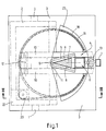
- Fig. 1 is a sectional view of an embodiment of the angular cutter according to the invention, seen along the line I-I in fig. 2.
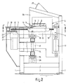
- Fig. 2 is a sectional view along the line II-II in fig. 1,
- Fig. 3 is a sectional view corresponding to that of fig. 2 wherein, however, the upper knife is shown in another position.
- The angular cutter shown in the drawing comprises a stationary frame including three
posts 1 and a plurality ofcross beams 2 connected thereto. Both theposts 1 and thecross beams 2 are constructed of tube sections having a rectangular cross-section. - On the upper side of the frame there is provided a work support table 3 for supporting a work piece, particularly a metal sheet. The work support table 3 will mostly be provided with means for positioning and/or clamping the work piece, such as adjustable stops and/or clamping fixtures (not shown).
- The angular cutter further comprises a
lower knife 5 mounted on afirst support part 4, and anupper knife 7 fixed to asecond support part 6 which is mounted movable relative to thefirst support part 4. Both thelower knife 5 and theupper knife 7 are provided with two each mutually co-operatingcutting edges 8 extending from atip 9 at a fixed angle, in this case of 30°, with respect to each other. The upper and lower knives are shaped such that theupper knife 7 can move into thelower knife 5 whereby theco-operating cutting edges 8 thereof are able to cut the work piece. The upper surface of thelower knife 5 is substantially flush with the upper surface of the work support table 3. Thecutting edges 8 of theupper knife 7, in the upper position thereof, extends inclined upwardly from thetip 9 so that the cutting action starts at thetip 9 and is displaced thereupon along thecutting edges 8 away from thetip 9. - The
first support part 4 includes two parallel spaced, mutually connectedhorizontal support beams 10 to which thelower knife 5 is attached. Under thelower knife 5 between thesupport beams 10 there is anadditional support block 11 for thelower knife 5, which is provided with a passage for the cut work piece parts. - The
second support part 6 is constructed of a plurality of tube sections having a large rectangular cross section so as to effectuate a very stiff structure. Thesecond support part 6 is pivotable about ahorizontal pivot shaft 12 extending parallel to the work support table 3 and perpendicular to the plane of symmetry of theupper knife 5 and thelower knife 7 and thepivot shaft 12 being connected to thefirst support part 4. Thepivot shaft 12 extends through bothsupport beams 10 of thefirst support part 4 and through the tube section of thesecond support part 6 and forms a rugged bearing for thesecond support part 6. - The
pivot shaft 12 is connected to thefirst support part 4 on the side of theknife tip 9 and is arranged a small distance below the cutting plane difined by thecutting edges 8 of thelower knife 5. - At the end of the
first support part 4 facing away from the pivot shaft there is pivotally attached an end of a hydraulic cylinder-rod assembly 13 of which the other end is pivotally connected to the lower portion of thesecond support part 6. The cylinder-rod assembly 13 serves as displacement means for theupper knife 7 so as to effect the cutting movement of theupper knife 7. - The
second support part 6 together with theupper knife 7 is guided relative to the first support part since the upright tube section extending near theupper knife 7 is guided between both of thesupport beams 10 of thefirst support part 4. The sides of the tube section extending parallel to the plane of symmetry of theupper knife 7 and being guided between thesupport beams 10 are constructed as guiding surfaces co-operating with guiding surfaces on the inner side of thesupport beams 10. This results in a confinement of the second support part parallel to the cutting plane perpendicular to the plane of symmetry of the upper and lower knives and hence in a very stiff guide. The guiding surfaces of the first or second support part may consist of a bearing material such as bearing bronze. - The
first support part 4 is provided on arotary shaft 14 being aligned with thetip 10 of thelower knife 5 and extending perpendicular to the cutting plane. Therotary shaft 14 is journalled inbearings cross beams 2 of the stationary frame. The upper end of therotary shaft 14 is attached in thesupport block 11 between thesupport beams 10, and therotary shaft 14 is guided through anopening 17 in thesecond support part 6 between thebearings first support part 4 is rotatable about therotary shaft 14 by means of achain 18 being guided about a circular segment-shaped rail 19 of thefirst support part 4 and being in engagement with atooth gear 20. Thistooth gear 20 is mounted on the shaft of anelectric motor 21 attached to atie plate 22 of the stationary frame. The ends of thechain 17 are tied to thesupport beams 10. - In the work support table there is saved a circular-segment-
shaped opening 23 for the passage of thelower knife 5 and theupper knife 7. The opening 23 is dimensioned such that the first andsecond support parts upper knives - At the lower end of the
rotary shaft 14 there is provided an angle measuring means 24 electronically measuring the angular rotation of therotary shaft 14 relative to the stationary frame. This angle measuring means 24 forms part of the computer control of the angular cutter, wherein both extreme angular positions of the lower andupper knives keyboard 25 whereupon theelectric motor 21 is adapted to be controlled by means of the information supplied by the angle measuring means 24. - The fixed work support table 3, on the side of the
knife tip 9, extends through to the neighbourhood of thelower knife 5 so that also small work pieces are permitted to be clamped on the work support table 3 in a simple and safe manner. Above the work support table 3 over theupper knive 7 and thesecond support part 6 connected thereto there is provided a protectional cap which is at least partly transparant for permitting a visable control of the upper andlower knives - Acccording to the invention there is provided an angular cutter comprising only very little parts but nevertheless having a multilateral rugged and safe construction.
- The invention is not restricted to the embodiment shown in the drawing by way of example, which can be varied in different way's within the scope of the invention.
Claims (10)
1. Angular cutter comprising a stationary frame, a lower knife provided on a first support part and an upper knife secured to a second support part mounted movable relative to the first support part, wherein the lower and upper knives are provided with two mutually co-operating cutting edges extending from their tip end at an angle with respect to each other, and the cutting edges of the lower knife defining a cutting plane, characterized in that the second support part together with the upper knife is connected to the first support part pivotable about a pivot axis extending substantially parallel to the cutting plane.
2. Angular cutter according to claim 1,
characterized in that the pivot axis is spaced a short distance from the cutting plane such that, during the cutting operation, the upper knife has a horizontal component of displacement which is directed away from the tip of the cutting edges.
characterized in that the pivot axis is spaced a short distance from the cutting plane such that, during the cutting operation, the upper knife has a horizontal component of displacement which is directed away from the tip of the cutting edges.
3. Angular cutter according to claim 2,
characterized in that the pivot axis is arranged below the cutting plane at the end of the tip of the cutting edges.
characterized in that the pivot axis is arranged below the cutting plane at the end of the tip of the cutting edges.
4. Angular cutter according to claim 3,
characterized in that a rectilinear displacement means engages the second support part at the end of the cutting edges facing away from the tip thereof.
characterized in that a rectilinear displacement means engages the second support part at the end of the cutting edges facing away from the tip thereof.
5. Angular cutter according to claim 4,
characterized in that between the first and second support parts there is arranged a guide extending perpendicular to the cutting plane, the guide guiding the second support part parallel to the pivot axis in a confined fashion.
characterized in that between the first and second support parts there is arranged a guide extending perpendicular to the cutting plane, the guide guiding the second support part parallel to the pivot axis in a confined fashion.
6. Angular cutter according to claim 5,
characterized in that the first and second support parts have two mutually co-operating guiding surfaces.
characterized in that the first and second support parts have two mutually co-operating guiding surfaces.
7. Angular cutter according to one of the preceding claims, characterized in that the second support part comprises beam sections having a substantially rectangular cross section.
8. Angular cutter according to one of the preceding claims, wherein the upper and lower knives have a fixed cutting edge angle and are commonly rotatable relative to the stationary frame about an axis of rotation aligned with the tip of the lower knife and extending perpendicular to the cutting plane, and the first support part being rotatably mounted to the stationary frame, characterized in that the second support part together with the upper knife fixed thereto are only and directly connected to the first support part pivotable about said pivot axis.
9. Angular cutter according to claim 8, having a work support table fixed to the stationary frame,
characterized in that the fixed work support table runs through to the neighbourhood of the lower knife on the side of the tip thereof, and there being provided in the work support table a circular-segment shaped opening for passage of the lower and upper knives.
characterized in that the fixed work support table runs through to the neighbourhood of the lower knife on the side of the tip thereof, and there being provided in the work support table a circular-segment shaped opening for passage of the lower and upper knives.
10. Angular cutter according to claim 8 or 9,
characterized in that the first support part is driven by a motor which is controlled by means of an electronic angle measuring means acting between the frame and the first support part.
characterized in that the first support part is driven by a motor which is controlled by means of an electronic angle measuring means acting between the frame and the first support part.
Applications Claiming Priority (2)
| Application Number | Priority Date | Filing Date | Title |
|---|---|---|---|
| NL8800418 | 1988-02-18 | ||
| NL8800418A NL8800418A (en) | 1988-02-18 | 1988-02-18 | CORNER SCISSORS. |
Publications (1)
| Publication Number | Publication Date |
|---|---|
| EP0329259A1 true EP0329259A1 (en) | 1989-08-23 |
Family
ID=19851815
Family Applications (1)
| Application Number | Title | Priority Date | Filing Date |
|---|---|---|---|
| EP89200397A Withdrawn EP0329259A1 (en) | 1988-02-18 | 1989-02-17 | Angular cutter |
Country Status (2)
| Country | Link |
|---|---|
| EP (1) | EP0329259A1 (en) |
| NL (1) | NL8800418A (en) |
Cited By (3)
| Publication number | Priority date | Publication date | Assignee | Title |
|---|---|---|---|---|
| EP0364883A2 (en) * | 1988-10-20 | 1990-04-25 | LUDWIG BOSCHERT MASCHINEN- UND APPARATEBAU GMBH & CO. KG | Corner shears with a system for changing the angle between the cutters |
| EP0820827A1 (en) * | 1996-07-24 | 1998-01-28 | Murata Kikai Kabushiki Kaisha | Work cutting apparatus |
| CN104227116A (en) * | 2013-06-20 | 2014-12-24 | 太仓子午电气有限公司 | Automatic board cutting machine |
Citations (6)
| Publication number | Priority date | Publication date | Assignee | Title |
|---|---|---|---|---|
| US2342946A (en) * | 1942-05-01 | 1944-02-29 | Letourneau Inc | Plunger guide unit |
| DE2040742A1 (en) * | 1970-08-17 | 1972-03-02 | Eugen Siempelkamp | Drop forging press - ith exact guidance during pressing |
| GB2111891A (en) * | 1981-10-22 | 1983-07-13 | Manuform Limited | A punching and/or forming tool |
| EP0102625A2 (en) * | 1982-09-07 | 1984-03-14 | Ludwig Boschert GmbH & Co. KG Maschinen- und Apparatebau | Notching device |
| CA1165992A (en) * | 1981-07-13 | 1984-04-24 | Trevor Iceton | Lid cutter |
| DE3433658A1 (en) * | 1984-09-13 | 1986-03-20 | Ludwig Boschert Maschinen- und Apparatebau GmbH & Co KG, 7850 Lörrach | Notching apparatus |
-
1988
- 1988-02-18 NL NL8800418A patent/NL8800418A/en not_active Application Discontinuation
-
1989
- 1989-02-17 EP EP89200397A patent/EP0329259A1/en not_active Withdrawn
Patent Citations (6)
| Publication number | Priority date | Publication date | Assignee | Title |
|---|---|---|---|---|
| US2342946A (en) * | 1942-05-01 | 1944-02-29 | Letourneau Inc | Plunger guide unit |
| DE2040742A1 (en) * | 1970-08-17 | 1972-03-02 | Eugen Siempelkamp | Drop forging press - ith exact guidance during pressing |
| CA1165992A (en) * | 1981-07-13 | 1984-04-24 | Trevor Iceton | Lid cutter |
| GB2111891A (en) * | 1981-10-22 | 1983-07-13 | Manuform Limited | A punching and/or forming tool |
| EP0102625A2 (en) * | 1982-09-07 | 1984-03-14 | Ludwig Boschert GmbH & Co. KG Maschinen- und Apparatebau | Notching device |
| DE3433658A1 (en) * | 1984-09-13 | 1986-03-20 | Ludwig Boschert Maschinen- und Apparatebau GmbH & Co KG, 7850 Lörrach | Notching apparatus |
Cited By (4)
| Publication number | Priority date | Publication date | Assignee | Title |
|---|---|---|---|---|
| EP0364883A2 (en) * | 1988-10-20 | 1990-04-25 | LUDWIG BOSCHERT MASCHINEN- UND APPARATEBAU GMBH & CO. KG | Corner shears with a system for changing the angle between the cutters |
| EP0364883A3 (en) * | 1988-10-20 | 1991-03-20 | LUDWIG BOSCHERT MASCHINEN- UND APPARATEBAU GMBH & CO. KG | Corner shears with a system for changing the angle between the cutters |
| EP0820827A1 (en) * | 1996-07-24 | 1998-01-28 | Murata Kikai Kabushiki Kaisha | Work cutting apparatus |
| CN104227116A (en) * | 2013-06-20 | 2014-12-24 | 太仓子午电气有限公司 | Automatic board cutting machine |
Also Published As
| Publication number | Publication date |
|---|---|
| NL8800418A (en) | 1989-09-18 |
Similar Documents
| Publication | Publication Date | Title |
|---|---|---|
| US10661467B2 (en) | Miter saw with adjustable fence | |
| US5404779A (en) | Saw table with compound movement of saw | |
| CA2036350C (en) | Vertical band saw | |
| US6334379B1 (en) | Mini-blind cut-down machine | |
| EP0242733A1 (en) | Sawing device | |
| GB2098910A (en) | Shearing machine | |
| US5271155A (en) | Hand circular saw | |
| US5010795A (en) | Apparatus for cutting metal and plastic sheet | |
| US4265154A (en) | Motorized miter saw fence mounting | |
| JP2632486B2 (en) | Steel shearing machine | |
| US5651297A (en) | Power saw fence guide | |
| US2894543A (en) | Mitering attachment for power saws | |
| EP0329259A1 (en) | Angular cutter | |
| EP1716987A1 (en) | Fence arrangement for a miter saw | |
| US6463837B2 (en) | Guiding device for a saw blade | |
| US2939358A (en) | Ledger blade adjustment means for shear machine | |
| US4384502A (en) | Motorized circular miter chop saw | |
| JP2589232Y2 (en) | Plywood edge cutting device | |
| EP0949048B1 (en) | Mitre saw with angularly adjustable fence | |
| JPH067859Y2 (en) | Sliding tabletop cutting machine | |
| EP0550920A2 (en) | Apparatus for working metal workpieces | |
| EP0238120A2 (en) | Guillotine shearing machine | |
| CN210025574U (en) | Safe type sawing machine cutting device | |
| CH469522A (en) | Hydraulic guillotine shear | |
| EP1036623A2 (en) | Mitre sawing machine |
Legal Events
| Date | Code | Title | Description |
|---|---|---|---|
| PUAI | Public reference made under article 153(3) epc to a published international application that has entered the european phase |
Free format text: ORIGINAL CODE: 0009012 |
|
| AK | Designated contracting states |
Kind code of ref document: A1 Designated state(s): AT BE CH DE ES FR GB GR IT LI LU NL SE |
|
| 17P | Request for examination filed |
Effective date: 19900215 |
|
| 17Q | First examination report despatched |
Effective date: 19910123 |
|
| STAA | Information on the status of an ep patent application or granted ep patent |
Free format text: STATUS: THE APPLICATION IS DEEMED TO BE WITHDRAWN |
|
| 18D | Application deemed to be withdrawn |
Effective date: 19920324 |