EP0328741A2 - Hydraulic inching drive system - Google Patents
Hydraulic inching drive system Download PDFInfo
- Publication number
- EP0328741A2 EP0328741A2 EP88118300A EP88118300A EP0328741A2 EP 0328741 A2 EP0328741 A2 EP 0328741A2 EP 88118300 A EP88118300 A EP 88118300A EP 88118300 A EP88118300 A EP 88118300A EP 0328741 A2 EP0328741 A2 EP 0328741A2
- Authority
- EP
- European Patent Office
- Prior art keywords
- plate cylinder
- printing press
- gear
- drive mechanism
- torque
- Prior art date
- Legal status (The legal status is an assumption and is not a legal conclusion. Google has not performed a legal analysis and makes no representation as to the accuracy of the status listed.)
- Granted
Links
- 230000007246 mechanism Effects 0.000 claims abstract description 56
- 238000000034 method Methods 0.000 claims description 10
- 230000003213 activating effect Effects 0.000 claims 2
- 230000000694 effects Effects 0.000 description 4
- 239000012530 fluid Substances 0.000 description 3
- 238000003825 pressing Methods 0.000 description 2
- 238000010276 construction Methods 0.000 description 1
- 238000004519 manufacturing process Methods 0.000 description 1
- 239000002184 metal Substances 0.000 description 1
Images

Classifications
-
- B—PERFORMING OPERATIONS; TRANSPORTING
- B41—PRINTING; LINING MACHINES; TYPEWRITERS; STAMPS
- B41F—PRINTING MACHINES OR PRESSES
- B41F13/00—Common details of rotary presses or machines
- B41F13/0008—Driving devices
-
- B—PERFORMING OPERATIONS; TRANSPORTING
- B41—PRINTING; LINING MACHINES; TYPEWRITERS; STAMPS
- B41P—INDEXING SCHEME RELATING TO PRINTING, LINING MACHINES, TYPEWRITERS, AND TO STAMPS
- B41P2213/00—Arrangements for actuating or driving printing presses; Auxiliary devices or processes
- B41P2213/70—Driving devices associated with particular installations or situations
- B41P2213/71—Inching drive mechanism, i.e. to obtain stepwise movement
Definitions
- This invention relates generally to a rotary printing press drive system. More particularly it relates to a novel drive mechanism which permits the low speed rotation of the plate and blanket cylinders of a disengaged printing press unit in an automated fashion.
- Printing presses such as those used for printing newspapers and the like, utilize plates which have the particular impression to be printed etched on them. These plates are attached to a portion of the printing press known as a plate cylinder. When printing newspapers and the like, these plates will need to be changed several times a day in order to reflect the different editions or different newspapers printed on each printing press unit.
- the press unit in order for a plate to be removed and changed on a plate cylinder, the press unit would have to be disengaged from the press drive system or the entire printing press stopped. With the press unit disengaged, the plate could then be removed from or placed on the plate cylinder by engaging in an activity known as "barring.”
- Barring is the common way to rotate a plate cylinder and remove or replace a particular plate. Barring consists of manually disengaging a press unit, inserting a metal bar in the gaps found beside the plate cylinder and using the bar as a lever to manually rotate the cylinder at a low speed. Thus, a pressman will "inch" the plate cylinder a fraction of a rotation, engage in the specific activity that required disengagement of the press unit (usually changing the plate), and repeat this process until the plate cylinder is fully rotated. This barring process is obviously very labor intensive, as well as time consuming.
- the inching drive mechanism of the present invention overcomes the foregoing disadvantages by allowing each individual press unit to be disengaged from the entire press drive system, and simultaneously allowing each disengaged unit to be rotated by a low speed motor.
- a drive mechanism which includes a mechanical power source capable of producing rotational output in either direction, a means for transmitting power which is operatively engaged to the mechanical power source, and a clutch system operatively connected to the power transmitting means and capable of engaging and disengaging the drive mechanism.
- the inching drive mechanism's main components are a hydraulically powered motor, a gear train and a pneumatic clutch system.
- the inching drive mechanism is disengaged.
- the plate and blanket cylinder gears are disengaged from the drive train of the printing press and engaged with the drive train of the inching drive mechanism.
- Mechanisms for disengaging the plate and blanket cylinders from the drive train of a printing press are known in the art.
- the inching drive system When the inching drive system is utilized, a pressman will simply disengage the plate and blanket cylinders for the individual unit from the drive system of the printing press, and then press a button to engage the inching drive mechanism. The pressman can then proceed to remove and replace plates from the plate cylinders while the drive mechanism rotates the plate cylinders at extremely low speeds. The plates on each printing press unit need not be changed simultaneously, nor does the pressman need to engage in "barring". Therefore, the present invention provides for efficiency in labor and time saving over what is currently known in the art.
- the inching drive mechanism also allows for the utilization of any auto-engagement feature.
- the auto-engagement feature on a printing press is old in the art, the present invention provides for its efficient utilization.
- the auto-engagement feature on a printing press functions to transfer the applied torque from the inching drive mechanism back to the drive system of the main printing press. This transfer is accomplished through a single position clutch which is in the disengaged portion of the press unit while the inching drive mechanism may be operational, but which is in the engaged portion of the press unit when the inching drive mechanism is disengaged.
- the inching drive system of the present invention drives the plate and blanket cylinders at a low speed, which in turn drives an idler gear which is connected to the single position clutch.
- the single position clutch engages, thus allowing the clutch plates to slide slowly against each other.
- the single position clutch reaches a second position, it becomes fully engaged.
- limit switches disengage the inching drive mechanism and transfer operation over to the main printing press drive system.
- individual press units 2 are shown, each having an inching drive mechanism 4 of the present invention and plate cylinders 6.
- FIG. 2 and FIG. 3 and using like numbers to designate like items to assist in understanding the views, the inching drive mechanism 4 and plate cylinder 6 are shown schematically.
- the main components of the inching drive mechanism are hydraulically powered motor, a gear train, and a pneumatic clutch system.
- the inching drive mechanism When the printing press is in the operational mode, the inching drive mechanism is disengaged.
- the plate and blanket cylinder gears are disengaged from the printing press drive train and engaged with and rotated by the inching drive mechanism.
- the hydraulic motor 16 Shortly after the inching drive mechanism 4 is activated, the hydraulic motor 16 begins operation.
- the hydraulic motor 16 obtains its power through the application of pressurized hydraulic fluids to the motor.
- a hydraulic motor 16 is utilized in the present invention because such a motor is capable of variable speeds unlike an AC motor and will achieve relatively high torque output at low speeds while still remaining small in size and weight, unlike a DC servo motor.
- any variable speed motor system can be utilized.
- Hydraulic fluid is applied to the hydraulic motor 16 through the hydraulic control valve 20.
- the hydraulic control valve 20 is actuated electrically.
- the application of hydraulic fluid to the hydraulic motor 16 causes a low-speed/high-torque output at the motor shaft 22 which extends from the motor.
- the motor shaft 22 of the hydraulic motor 16 is connected to the motor gear 24.
- the motor gear 24 is a spur gear which transmits the torque from the hydraulic motor 16 to the inching drive mechanism's gear train consisting of motor gear 24, idler gear 26 and shaft gear 14.
- the motor gear 24 is connected to an idler spur gear 26.
- the idler spur gear 26 in turn transmits torque to the shaft gear 14.
- Shaft gear 14 is keyed to the clutch shaft 18.
- Clutch shaft 18 is in turn keyed to the clutch housing 28.
- the driving cup 30 comprises: a series of projections or teeth attached in conjunction with a hollowed out cup-shaped housing. The teeth are interleaved between the housing of the driving cup and the clutch 10 such that when the clutch 10 is disengaged, the teeth of the driving cup 30 spin freely. When the clutch 10 is engaged, the teeth of the driving cup 30 are driven by the clutch plates 31.
- the friction generated from these clutch plates 31 pressing together transfers torque from the clutch 10 to the driving cup 30.
- the driving cup 30 is, in turn, attached to the output gear 12.
- the torque transmitted from the hydraulic motor 16, as reduced by the gear train consisting of motor gear 24, idler gear 26 and shaft gear 14, is transmitted through the clutch shaft 18 to the clutch 10.
- the output gear 12 engages a gear 32 attached to the plate cylinder 6, and transmits the low-speed/high-torque output of the gear train to the plate cylinder gear 32.
- the plate cylinder gear 32 is directly attached to the plate cylinder 6.
- the rotation of the plate cylinder gear 32 at low speed would likewise rotate the plate cylinder 6 at the same low speed.
- the inching drive function is achieved.
- the plate cylinder gear 32 engages a series of gears within the press unit itself, namely, the blanket cylinder gear, the opposing blanket cylinder gear, and finally the opposing plate cylinder gear.
- the details of this gearing arrangement are not an important part of the present invention and are not shown in the drawings.
- the variable speed of the hydraulic motor 16 allows a pressman to control the inching speed of all of the plate and blanket cylinders.
- the output gear 12 which engages plate cylinder gear 32 remains engaged with plate cylinder gear 32 whether or not the inching drive mechanism 4 is engaged.
- the clutch 10 is disengaged and the output gear 12 spins freely, independent of the inching drive mechanism.
- no torque is transmitted to output gear 12, and output gear 12 spins freely on a system of bearings 34.
Abstract
Description
- This invention relates generally to a rotary printing press drive system. More particularly it relates to a novel drive mechanism which permits the low speed rotation of the plate and blanket cylinders of a disengaged printing press unit in an automated fashion.
- Printing presses, such as those used for printing newspapers and the like, utilize plates which have the particular impression to be printed etched on them. These plates are attached to a portion of the printing press known as a plate cylinder. When printing newspapers and the like, these plates will need to be changed several times a day in order to reflect the different editions or different newspapers printed on each printing press unit.
- Heretofore, in order for a plate to be removed and changed on a plate cylinder, the press unit would have to be disengaged from the press drive system or the entire printing press stopped. With the press unit disengaged, the plate could then be removed from or placed on the plate cylinder by engaging in an activity known as "barring."
- Barring is the common way to rotate a plate cylinder and remove or replace a particular plate. Barring consists of manually disengaging a press unit, inserting a metal bar in the gaps found beside the plate cylinder and using the bar as a lever to manually rotate the cylinder at a low speed. Thus, a pressman will "inch" the plate cylinder a fraction of a rotation, engage in the specific activity that required disengagement of the press unit (usually changing the plate), and repeat this process until the plate cylinder is fully rotated. This barring process is obviously very labor intensive, as well as time consuming.
- If a press unit is not disengaged from the main drive of the printing press, all of the plates on the press units must be changed simultaneously. Under such circumstances, several pressmen simultaneously must remove and replace plates on each individual press unit in the entire press while the entire press is driven at extremely low inching speeds. Naturally, this activity results in a great disruption of pressroom activities.
- The inching drive mechanism of the present invention overcomes the foregoing disadvantages by allowing each individual press unit to be disengaged from the entire press drive system, and simultaneously allowing each disengaged unit to be rotated by a low speed motor.
- It is an object of the present invention to provide an inching drive mechanism within a rotary printing press drive system which is designed to provide for individual press unit control and to facilitate the addition or removal of plates from plate cylinders.
- It is another object of the present invention to provide a drive mechanism which can be operated in forward and reverse directions;
- It is another object of the present invention to provide a drive mechanism which is compatible for use on a variety of different types of printing presses.
- It is still another object of the present invention to provide a drive mechanism which will not require high voltage AC or DC electrical power.
- It is yet another object of the present invention to provide a drive mechanism which will allow for the efficient utilization of the auto-engagement feature of a main printing press drive system.
- It is another object of the present invention to provide a drive mechanism which is a labor and time saving device.
- It is still another object of the present invention to provide a drive mechanism which is simple in construction.
- It is a still further object of the present invention to provide a drive mechanism which is compact and inexpensive to manufacture.
- Generally, the objects of the present invention are accomplished through a drive mechanism which includes a mechanical power source capable of producing rotational output in either direction, a means for transmitting power which is operatively engaged to the mechanical power source, and a clutch system operatively connected to the power transmitting means and capable of engaging and disengaging the drive mechanism.
- In the preferred embodiment, the inching drive mechanism's main components are a hydraulically powered motor, a gear train and a pneumatic clutch system. When the printing press is in the operational mode, the inching drive mechanism is disengaged. When the inching drive mechanism is operational, the plate and blanket cylinder gears are disengaged from the drive train of the printing press and engaged with the drive train of the inching drive mechanism. Mechanisms for disengaging the plate and blanket cylinders from the drive train of a printing press are known in the art.
- When the inching drive system is utilized, a pressman will simply disengage the plate and blanket cylinders for the individual unit from the drive system of the printing press, and then press a button to engage the inching drive mechanism. The pressman can then proceed to remove and replace plates from the plate cylinders while the drive mechanism rotates the plate cylinders at extremely low speeds. The plates on each printing press unit need not be changed simultaneously, nor does the pressman need to engage in "barring". Therefore, the present invention provides for efficiency in labor and time saving over what is currently known in the art.
- The inching drive mechanism also allows for the utilization of any auto-engagement feature. Although the auto-engagement feature on a printing press is old in the art, the present invention provides for its efficient utilization.
- The auto-engagement feature on a printing press functions to transfer the applied torque from the inching drive mechanism back to the drive system of the main printing press. This transfer is accomplished through a single position clutch which is in the disengaged portion of the press unit while the inching drive mechanism may be operational, but which is in the engaged portion of the press unit when the inching drive mechanism is disengaged.
- To enable the auto-engagement system, the inching drive system of the present invention drives the plate and blanket cylinders at a low speed, which in turn drives an idler gear which is connected to the single position clutch. At the low rotating speed, the single position clutch engages, thus allowing the clutch plates to slide slowly against each other. As the single position clutch reaches a second position, it becomes fully engaged. At this point, limit switches disengage the inching drive mechanism and transfer operation over to the main printing press drive system.
- The accompanying drawings, which are incorporated in and constitute part of the specification, illustrate embodiments of the invention and, together with the description, serve to explain the principles of the invention.
- FIG. 1 is a side elevation view of individual press units showing the general location of the plate cylinders and inching drive mechanisms;
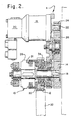
- FIG. 2 shows a sectional view of the inching drive mechanism;
- FIG. 3 is an exploded, schematic view showing the gear connections of the inching drive mechanism and the plate cylinder.
- The invention described in this specification and shown in the drawings utilizes certain principles and/or concepts as set forth herein and in the claims. Those skilled in the graphic printing art will realize that these principles and/or concepts are capable of being utilized in a variety of embodiments which may differ from the exact embodiments utilized herein for illustrative purposes. For this reason, the present invention is not to be construed as being solely limited to the illustrative embodiments.
- Referring now to FIG. 1,
individual press units 2 are shown, each having aninching drive mechanism 4 of the present invention andplate cylinders 6. - Turning now to FIG. 2 and FIG. 3, and using like numbers to designate like items to assist in understanding the views, the
inching drive mechanism 4 andplate cylinder 6 are shown schematically. - The main components of the inching drive mechanism are hydraulically powered motor, a gear train, and a pneumatic clutch system. When the printing press is in the operational mode, the inching drive mechanism is disengaged. When the inching drive mechanism is operational, the plate and blanket cylinder gears are disengaged from the printing press drive train and engaged with and rotated by the inching drive mechanism.
- When the
inching drive mechanism 4 is ready to be activated, theplate cylinders 6 are disconnected from the printing press drive system. A button is pushed on the control panel of the printing press which thereafter sounds an alarm indicating that the inching drive mechanism is about to be engaged. Pneumatic pressure is applied to theclutch 10 when theinching drive mechanism 4 engages. This pressure, in turn, engages the clutch. When the clutch is engaged, thehelical output gear 12, shown in FIGS. 2 and 3, no longer operates as an idler gear as it does when the press is in normal operation. Instead,output gear 12 becomes engaged via the clutch system. The torque transmitted byshaft gear 14 when themotor 16 is engaged and the gear train is in motion is transmitted viaclutch shaft 18 tooutput gear 12. - Shortly after the
inching drive mechanism 4 is activated, thehydraulic motor 16 begins operation. Thehydraulic motor 16 obtains its power through the application of pressurized hydraulic fluids to the motor. Ahydraulic motor 16 is utilized in the present invention because such a motor is capable of variable speeds unlike an AC motor and will achieve relatively high torque output at low speeds while still remaining small in size and weight, unlike a DC servo motor. Obviously, while a hydraulic motor is used in this preferred embodiment, any variable speed motor system can be utilized. Likewise, while a pneumatic clutch is first engaged in the inching drive mechanism, other clutches or means for engaging and disengaging the inching drive mechanism can be utilized. Hydraulic fluid is applied to thehydraulic motor 16 through thehydraulic control valve 20. Thehydraulic control valve 20 is actuated electrically. The application of hydraulic fluid to thehydraulic motor 16 causes a low-speed/high-torque output at themotor shaft 22 which extends from the motor. Themotor shaft 22 of thehydraulic motor 16 is connected to themotor gear 24. Themotor gear 24 is a spur gear which transmits the torque from thehydraulic motor 16 to the inching drive mechanism's gear train consisting ofmotor gear 24,idler gear 26 andshaft gear 14. - The
motor gear 24 is connected to anidler spur gear 26. Theidler spur gear 26 in turn transmits torque to theshaft gear 14.Shaft gear 14 is keyed to theclutch shaft 18.Clutch shaft 18 is in turn keyed to theclutch housing 28. When pneumatic pressure is applied and the clutch 10 is engaged, torque fromclutch shaft 18 is transmitted through the clutch 10 to the drivingcup 30. The drivingcup 30 comprises: a series of projections or teeth attached in conjunction with a hollowed out cup-shaped housing. The teeth are interleaved between the housing of the driving cup and the clutch 10 such that when the clutch 10 is disengaged, the teeth of the drivingcup 30 spin freely. When the clutch 10 is engaged, the teeth of the drivingcup 30 are driven by theclutch plates 31. The friction generated from theseclutch plates 31 pressing together transfers torque from the clutch 10 to the drivingcup 30. The drivingcup 30 is, in turn, attached to theoutput gear 12. Thus, the torque transmitted from thehydraulic motor 16, as reduced by the gear train consisting ofmotor gear 24,idler gear 26 andshaft gear 14, is transmitted through theclutch shaft 18 to the clutch 10. When clutch 10 is engaged, the torque is then transmitted, via the pressing together of theclutch plates 31 of the clutch 10 from theclutch shaft 18 to the clutch 10 to the drivingcup 30 and subsequently to theoutput gear 12. Theoutput gear 12, in turn, engages agear 32 attached to theplate cylinder 6, and transmits the low-speed/high-torque output of the gear train to theplate cylinder gear 32. Theplate cylinder gear 32 is directly attached to theplate cylinder 6. Thus, the rotation of theplate cylinder gear 32 at low speed would likewise rotate theplate cylinder 6 at the same low speed. Thus, the inching drive function is achieved. - The
plate cylinder gear 32 engages a series of gears within the press unit itself, namely, the blanket cylinder gear, the opposing blanket cylinder gear, and finally the opposing plate cylinder gear. The details of this gearing arrangement are not an important part of the present invention and are not shown in the drawings. Thus, the entire cylinder system of a printing press is inched forward or reverse. The variable speed of thehydraulic motor 16 allows a pressman to control the inching speed of all of the plate and blanket cylinders. - It should also be noted that the
output gear 12 which engagesplate cylinder gear 32 remains engaged withplate cylinder gear 32 whether or not the inchingdrive mechanism 4 is engaged. When the inchingdrive mechanism 4 is not engaged, the clutch 10 is disengaged and theoutput gear 12 spins freely, independent of the inching drive mechanism. When the inchingdrive mechanism 4 is disengaged, no torque is transmitted tooutput gear 12, andoutput gear 12 spins freely on a system ofbearings 34.
Claims (18)
Applications Claiming Priority (2)
| Application Number | Priority Date | Filing Date | Title |
|---|---|---|---|
| US07/158,244 US4836112A (en) | 1988-02-19 | 1988-02-19 | Hydraulic inching drive system |
| US158244 | 1988-02-19 |
Publications (3)
| Publication Number | Publication Date |
|---|---|
| EP0328741A2 true EP0328741A2 (en) | 1989-08-23 |
| EP0328741A3 EP0328741A3 (en) | 1990-06-13 |
| EP0328741B1 EP0328741B1 (en) | 1994-04-13 |
Family
ID=22567254
Family Applications (1)
| Application Number | Title | Priority Date | Filing Date |
|---|---|---|---|
| EP88118300A Expired - Lifetime EP0328741B1 (en) | 1988-02-19 | 1988-11-03 | Hydraulic inching drive system |
Country Status (5)
| Country | Link |
|---|---|
| US (1) | US4836112A (en) |
| EP (1) | EP0328741B1 (en) |
| JP (1) | JPH0741706B2 (en) |
| CA (1) | CA1309895C (en) |
| DE (2) | DE328741T1 (en) |
Cited By (3)
| Publication number | Priority date | Publication date | Assignee | Title |
|---|---|---|---|---|
| EP0478165A1 (en) * | 1990-09-06 | 1992-04-01 | Sdb Engineering | A drive system or isolating system for a web printing machine |
| DE4223583A1 (en) * | 1992-07-17 | 1994-01-20 | Heidelberger Druckmasch Ag | Printing machine with several forme cylinders - which are mutually independently rotatable into any arbitrary position |
| EP0834398A1 (en) * | 1996-10-02 | 1998-04-08 | MAN Roland Druckmaschinen AG | Drive for a sheet-fed offset press |
Families Citing this family (7)
| Publication number | Priority date | Publication date | Assignee | Title |
|---|---|---|---|---|
| DE3820026A1 (en) * | 1988-06-13 | 1989-12-14 | Heidelberger Druckmasch Ag | DEVICE FOR THE POWERFUL CLUTCHING OF A FIXED GEAR WHEEL AND AN ADJUSTING GEAR WHEEL ON A CYLINDER OF A TURNING DEVICE IN AN ARC ROTATION PRINTING MACHINE AND ELECTRICAL PROTECTION OF SUCH A DEVICE |
| JPH0698746B2 (en) * | 1989-03-30 | 1994-12-07 | アキヤマ印刷機製造株式会社 | Plate clamping device for sheet-fed printing press |
| US5109770A (en) * | 1989-09-22 | 1992-05-05 | Oxy-Dry Corporation | Printing cylinder cleaning system |
| JP2515387Y2 (en) * | 1989-12-26 | 1996-10-30 | 株式会社小森コーポレーション | Printer prime mover |
| DE4013462A1 (en) * | 1990-04-27 | 1991-11-07 | Heidelberger Druckmasch Ag | DEVICE FOR LACQUERING PRINTED SHEETS ON PRINTING MACHINES |
| CN101850647B (en) * | 2009-03-31 | 2014-12-10 | 海德堡印刷机械股份公司 | Rotary transfer apparatus for transferring different media |
| US11845624B2 (en) * | 2020-11-24 | 2023-12-19 | Ricoh Company, Ltd. | Conveying device and liquid discharge apparatus |
Citations (3)
| Publication number | Priority date | Publication date | Assignee | Title |
|---|---|---|---|---|
| US2003798A (en) * | 1934-06-07 | 1935-06-04 | Cottrell C B & Sons Co | Offset printing press |
| GB1308585A (en) * | 1971-11-04 | 1973-02-21 | Polygraph Leipzig | Printing machines incorporating hydraulic drive arrangements |
| US4566385A (en) * | 1982-06-03 | 1986-01-28 | Veb Kombinat Polygraph "Werner Lamberz" Leipzig | Hydraulic drive for multi-color sheet-fed rotary printing machines |
Family Cites Families (30)
| Publication number | Priority date | Publication date | Assignee | Title |
|---|---|---|---|---|
| US2219734A (en) * | 1939-10-26 | 1940-10-29 | Cottrell C B & Sons Co | Driving mechanism for rotary printing presses |
| GB704137A (en) * | 1952-02-19 | 1954-02-17 | Jean Paul Deck | Improvements in means for driving the printing cylinders of a printing machine |
| US2863387A (en) * | 1954-03-26 | 1958-12-09 | Hamilton Tool Co | Means for varying the phase relationship of the cylinders of a printing press |
| US2948216A (en) * | 1958-07-28 | 1960-08-09 | Harris Intertype Corp | Plate cylinder register mechanism |
| US3191531A (en) * | 1963-05-24 | 1965-06-29 | Wood Newspaper Mach Corp | Press drive means |
| US3398681A (en) * | 1965-08-26 | 1968-08-27 | Hamada Printing Press | Mechanism for driving the plate and impression cylinders of a printing press |
| US3565006A (en) * | 1968-08-29 | 1971-02-23 | Koppers Co Inc | Apparatus for changing and indicating the rotary and axial position of a printing member |
| DE2014070C3 (en) * | 1970-03-24 | 1974-01-10 | Roland Offsetmaschinenfabrik Faber & Schleicher Ag, 6050 Offenbach | Drive of a rotary printing press |
| DE2014753C3 (en) * | 1970-03-26 | 1974-01-10 | Roland Offsetmaschinenfabrik Faber & Schleicher Ag, 6050 Offenbach | Drive of a rotary printing press |
| US3641933A (en) * | 1970-06-08 | 1972-02-15 | North American Rockwell | Registry mechanism for printing units |
| US3724368A (en) * | 1970-06-17 | 1973-04-03 | Harris Intertype Corp | Harmonic drive register adjustment device for a printing press |
| US3717092A (en) * | 1970-11-23 | 1973-02-20 | Harris Intertype Corp | Registering mechanism for printing press |
| JPS492605A (en) * | 1972-03-31 | 1974-01-10 | ||
| US3742850A (en) * | 1972-04-17 | 1973-07-03 | Faustel Inc | Registration adjustment mechanism |
| US3793899A (en) * | 1972-09-11 | 1974-02-26 | Creusot Loire | Apparatus for angular and axial regulation of a printing cylinder |
| US3817176A (en) * | 1972-11-02 | 1974-06-18 | Int Machine Prod Inc | Printing cylinder register control unit |
| US3841216A (en) * | 1972-12-07 | 1974-10-15 | Hamilton Tool Co | Method of and apparatus for correcting deviations in length and registration in a continuous strip of material |
| US4183296A (en) * | 1973-07-05 | 1980-01-15 | Heidelberger Druckmaschinen Aktiengesellschaft | Drive system for sheet-fed rotary printing presses with tandem-mounted printing units |
| CA1029240A (en) * | 1973-08-01 | 1978-04-11 | Harris Corporation | Printing press drive system |
| DE2340263C3 (en) * | 1973-08-09 | 1980-04-24 | Heidelberger Druckmaschinen Ag, 6900 Heidelberg | Drive for multi-color sheet-fed rotary printing machines in a row arrangement with at least two printing units |
| JPS5931467B2 (en) * | 1977-04-27 | 1984-08-02 | 株式会社東京機械製作所 | Plate cylinder device in rotary printing press |
| DE2835915C3 (en) * | 1978-08-16 | 1981-10-15 | Rotaprint Gmbh, 1000 Berlin | Device for manually setting the angular position and for turning an electrically driven rotary offset printing machine |
| SE426153B (en) * | 1979-01-22 | 1982-12-13 | Wifag Maschf | DRIVE DEVICE FOR A ROLLER OFFSET PRESSURE MACHINE |
| US4240346A (en) * | 1979-01-29 | 1980-12-23 | Harris Corporation | Web printing press |
| JPS5680464A (en) * | 1979-12-05 | 1981-07-01 | Ryobi Ltd | Image position adjustment device for perfecting machine |
| DE3048840C1 (en) * | 1980-12-23 | 1983-03-10 | M.A.N.- Roland Druckmaschinen AG, 6050 Offenbach | Reversible direction of rotation drive for a web-fed rotary printing press with a ten-cylinder printing unit |
| DD207517B1 (en) * | 1982-06-03 | 1988-06-15 | Foerster Karl Heinz | DEVICE FOR POSITIONING TO PRINTING MACHINES |
| DE3405455C1 (en) * | 1984-02-16 | 1985-08-14 | M.A.N.- Roland Druckmaschinen AG, 6050 Offenbach | Circumferential register setting device on rotary printing presses |
| US4572074A (en) * | 1984-11-14 | 1986-02-25 | Harris Graphics Corporation | Multi-unit press register |
| US4706566A (en) * | 1986-02-12 | 1987-11-17 | Miyakoshi Printing Machinery Co., Ltd. | Method of reconnecting drive shaft sections in phase in a web printing press having a print station and a perforating or like processing station |
-
1988
- 1988-02-19 US US07/158,244 patent/US4836112A/en not_active Expired - Lifetime
- 1988-11-03 DE DE198888118300T patent/DE328741T1/en active Pending
- 1988-11-03 DE DE3889099T patent/DE3889099T2/en not_active Expired - Fee Related
- 1988-11-03 EP EP88118300A patent/EP0328741B1/en not_active Expired - Lifetime
- 1988-12-26 JP JP63326408A patent/JPH0741706B2/en not_active Expired - Fee Related
-
1989
- 1989-02-10 CA CA000590817A patent/CA1309895C/en not_active Expired - Fee Related
Patent Citations (3)
| Publication number | Priority date | Publication date | Assignee | Title |
|---|---|---|---|---|
| US2003798A (en) * | 1934-06-07 | 1935-06-04 | Cottrell C B & Sons Co | Offset printing press |
| GB1308585A (en) * | 1971-11-04 | 1973-02-21 | Polygraph Leipzig | Printing machines incorporating hydraulic drive arrangements |
| US4566385A (en) * | 1982-06-03 | 1986-01-28 | Veb Kombinat Polygraph "Werner Lamberz" Leipzig | Hydraulic drive for multi-color sheet-fed rotary printing machines |
Cited By (4)
| Publication number | Priority date | Publication date | Assignee | Title |
|---|---|---|---|---|
| EP0478165A1 (en) * | 1990-09-06 | 1992-04-01 | Sdb Engineering | A drive system or isolating system for a web printing machine |
| DE4223583A1 (en) * | 1992-07-17 | 1994-01-20 | Heidelberger Druckmasch Ag | Printing machine with several forme cylinders - which are mutually independently rotatable into any arbitrary position |
| DE4223583B4 (en) * | 1992-07-17 | 2005-02-24 | Heidelberger Druckmaschinen Ag | Method for driving the plate change in a sheet-fed press and drive for performing the method |
| EP0834398A1 (en) * | 1996-10-02 | 1998-04-08 | MAN Roland Druckmaschinen AG | Drive for a sheet-fed offset press |
Also Published As
| Publication number | Publication date |
|---|---|
| US4836112A (en) | 1989-06-06 |
| CA1309895C (en) | 1992-11-10 |
| EP0328741B1 (en) | 1994-04-13 |
| DE3889099T2 (en) | 1994-07-28 |
| JPH01218834A (en) | 1989-09-01 |
| JPH0741706B2 (en) | 1995-05-10 |
| DE328741T1 (en) | 1989-12-07 |
| EP0328741A3 (en) | 1990-06-13 |
| DE3889099D1 (en) | 1994-05-19 |
Similar Documents
| Publication | Publication Date | Title |
|---|---|---|
| US4836112A (en) | Hydraulic inching drive system | |
| US4833982A (en) | Printing cylinder positioning system | |
| US4696229A (en) | Rotary offset printing press equipped for flying plate change | |
| US6668721B2 (en) | Rotary printing press capable of nonstop printing during a change of printing plates | |
| EP1589387A3 (en) | Method and device for synchronously controlling multiple printing presses or multiple units in printing press | |
| US3516355A (en) | Multicolor sheet printing machine drive | |
| US5184551A (en) | Printing press | |
| US6289805B1 (en) | Device and method for driving a printing cylinder | |
| US4833983A (en) | Adjustment apparatus for adjusting the speed of a plate roller relative to a pressing roller in a multi-color plastic bag printer | |
| EP0764604A3 (en) | Drive device for a folder in a printing press | |
| JPS61273958A (en) | Paper-roll offset rotary press capable of instantaneously exchanging plate | |
| EP0508789A1 (en) | Double-acting type dynamic back spacing removed driving system | |
| JPH0592558A (en) | Method for mutual adjustment of each color image in multi-color rotary printing machine | |
| JPH06190598A (en) | Driving force transfer device for machine press | |
| EP1500501A3 (en) | Driving apparatus in printing press | |
| CA1316040C (en) | Rotary offset printing machine system | |
| JPS58220750A (en) | Method and device for determining position in printer | |
| WO2001008972A3 (en) | Downlock-pin actuator apparatus | |
| EP0824068A3 (en) | Taking-up backlash in the drive unit of a printing press | |
| JP3428048B2 (en) | Drive force transmission device for mechanical press | |
| GB2037382A (en) | Power Transmission Device | |
| JPH04146149A (en) | Sheet printer provided with reversing mechanism | |
| US7383771B2 (en) | Web-fed rotary printing unit | |
| GB2188702A (en) | Drive transmitting apparatus | |
| KR900000305Y1 (en) | Multi-plate clutch assembly for ship |
Legal Events
| Date | Code | Title | Description |
|---|---|---|---|
| PUAI | Public reference made under article 153(3) epc to a published international application that has entered the european phase |
Free format text: ORIGINAL CODE: 0009012 |
|
| AK | Designated contracting states |
Kind code of ref document: A2 Designated state(s): CH DE FR GB LI SE |
|
| EL | Fr: translation of claims filed | ||
| DET | De: translation of patent claims | ||
| PUAL | Search report despatched |
Free format text: ORIGINAL CODE: 0009013 |
|
| AK | Designated contracting states |
Kind code of ref document: A3 Designated state(s): CH DE FR GB LI SE |
|
| 17P | Request for examination filed |
Effective date: 19901019 |
|
| 17Q | First examination report despatched |
Effective date: 19920910 |
|
| GRAA | (expected) grant |
Free format text: ORIGINAL CODE: 0009210 |
|
| AK | Designated contracting states |
Kind code of ref document: B1 Designated state(s): CH DE FR GB LI SE |
|
| REF | Corresponds to: |
Ref document number: 3889099 Country of ref document: DE Date of ref document: 19940519 |
|
| ET | Fr: translation filed | ||
| EAL | Se: european patent in force in sweden |
Ref document number: 88118300.8 |
|
| PLBE | No opposition filed within time limit |
Free format text: ORIGINAL CODE: 0009261 |
|
| STAA | Information on the status of an ep patent application or granted ep patent |
Free format text: STATUS: NO OPPOSITION FILED WITHIN TIME LIMIT |
|
| 26N | No opposition filed | ||
| REG | Reference to a national code |
Ref country code: CH Ref legal event code: PUE Owner name: ROCKWELL INTERNATIONAL CORPORATION TRANSFER- GOSS |
|
| REG | Reference to a national code |
Ref country code: FR Ref legal event code: TP |
|
| REG | Reference to a national code |
Ref country code: GB Ref legal event code: 732E |
|
| REG | Reference to a national code |
Ref country code: GB Ref legal event code: IF02 |
|
| PGFP | Annual fee paid to national office [announced via postgrant information from national office to epo] |
Ref country code: GB Payment date: 20051026 Year of fee payment: 18 |
|
| PGFP | Annual fee paid to national office [announced via postgrant information from national office to epo] |
Ref country code: FR Payment date: 20051117 Year of fee payment: 18 |
|
| PGFP | Annual fee paid to national office [announced via postgrant information from national office to epo] |
Ref country code: SE Payment date: 20051125 Year of fee payment: 18 Ref country code: CH Payment date: 20051125 Year of fee payment: 18 |
|
| PGFP | Annual fee paid to national office [announced via postgrant information from national office to epo] |
Ref country code: DE Payment date: 20060102 Year of fee payment: 18 |
|
| PG25 | Lapsed in a contracting state [announced via postgrant information from national office to epo] |
Ref country code: SE Free format text: LAPSE BECAUSE OF NON-PAYMENT OF DUE FEES Effective date: 20061104 |
|
| PG25 | Lapsed in a contracting state [announced via postgrant information from national office to epo] |
Ref country code: LI Free format text: LAPSE BECAUSE OF NON-PAYMENT OF DUE FEES Effective date: 20061130 Ref country code: CH Free format text: LAPSE BECAUSE OF NON-PAYMENT OF DUE FEES Effective date: 20061130 |
|
| PG25 | Lapsed in a contracting state [announced via postgrant information from national office to epo] |
Ref country code: DE Free format text: LAPSE BECAUSE OF NON-PAYMENT OF DUE FEES Effective date: 20070601 |
|
| REG | Reference to a national code |
Ref country code: CH Ref legal event code: PL |
|
| EUG | Se: european patent has lapsed | ||
| GBPC | Gb: european patent ceased through non-payment of renewal fee |
Effective date: 20061103 |
|
| REG | Reference to a national code |
Ref country code: FR Ref legal event code: ST Effective date: 20070731 |
|
| PG25 | Lapsed in a contracting state [announced via postgrant information from national office to epo] |
Ref country code: GB Free format text: LAPSE BECAUSE OF NON-PAYMENT OF DUE FEES Effective date: 20061103 |
|
| PG25 | Lapsed in a contracting state [announced via postgrant information from national office to epo] |
Ref country code: FR Free format text: LAPSE BECAUSE OF NON-PAYMENT OF DUE FEES Effective date: 20061130 |