EP0328272B1 - Shear stiffness measuring method - Google Patents
Shear stiffness measuring method Download PDFInfo
- Publication number
- EP0328272B1 EP0328272B1 EP89300720A EP89300720A EP0328272B1 EP 0328272 B1 EP0328272 B1 EP 0328272B1 EP 89300720 A EP89300720 A EP 89300720A EP 89300720 A EP89300720 A EP 89300720A EP 0328272 B1 EP0328272 B1 EP 0328272B1
- Authority
- EP
- European Patent Office
- Prior art keywords
- sample
- angle
- measuring
- clamps
- shear stiffness
- Prior art date
- Legal status (The legal status is an assumption and is not a legal conclusion. Google has not performed a legal analysis and makes no representation as to the accuracy of the status listed.)
- Expired - Lifetime
Links
Images


Classifications
-
- G—PHYSICS
- G01—MEASURING; TESTING
- G01N—INVESTIGATING OR ANALYSING MATERIALS BY DETERMINING THEIR CHEMICAL OR PHYSICAL PROPERTIES
- G01N3/00—Investigating strength properties of solid materials by application of mechanical stress
- G01N3/26—Investigating twisting or coiling properties
-
- G—PHYSICS
- G01—MEASURING; TESTING
- G01N—INVESTIGATING OR ANALYSING MATERIALS BY DETERMINING THEIR CHEMICAL OR PHYSICAL PROPERTIES
- G01N2203/00—Investigating strength properties of solid materials by application of mechanical stress
- G01N2203/0014—Type of force applied
- G01N2203/0021—Torsional
-
- G—PHYSICS
- G01—MEASURING; TESTING
- G01N—INVESTIGATING OR ANALYSING MATERIALS BY DETERMINING THEIR CHEMICAL OR PHYSICAL PROPERTIES
- G01N2203/00—Investigating strength properties of solid materials by application of mechanical stress
- G01N2203/02—Details not specific for a particular testing method
- G01N2203/026—Specifications of the specimen
- G01N2203/0262—Shape of the specimen
- G01N2203/0278—Thin specimens
- G01N2203/0282—Two dimensional, e.g. tapes, webs, sheets, strips, disks or membranes
Definitions
- This invention relates to an instrument and method for testing paperboard products and assessing the structural properties of paperboard during manufacture.
- this invention is concerned with measuring shear stiffness of the corrugating medium in corrugated paperboard.
- Measurement of shear stiffness provides an important parameter in defining the structural properties of paperboard and for determining the strength of corrugated paperboard panels for end use applications.
- the first of these methods requires a lot of testing and for relatively stiff cores can give low results due to local buckling at the point of application of the central load.
- the second method requires attaching the specimen to a rigid backing strip by gluing or some other means. This procedure is tedious and the results from this method are very variable due to the very small deflections involved during measurement.
- this invention relates to a method of asssessing damage to corrugated board mediums during printing and box manufacture.
- This invention provides a more accurate measure of medium damage by measuring medium shear stiffness in the machine direction.
- US-A-2843390 discloses a fluid operated clamping jaw which could be used in a torsion testing machine employing a method of determining the shear stiffness of a material as an aid in processing the material, comprising placing a sample of the material between two clamps and subjecting the sample to a twisting force.
- the measurements can also be made with varying conditions of humidity and varying degrees of crush applied to the sample to determine performance of the medium under varying conditions.
- the device useful in carrying out the method of this invention essentially comprises a pair of axially aligned clamps at least one clamp being pivoted for rotation in a plane perpendicular to the alignment axis and means for measuring the force applied to rotate one of said clamps and means for measuring the angle of rotation.
- the device can be manually operable with the addition of weights to a lever arm or the like to produce rotation of one clamp relative to the other.
- the device can be mounted on a force measuring instrument such as an INSTRON and the rotatable clamp moved to a constant maximum angle of rotation with measurement of the force required to achieve that. Such a measurement can be repeated serially to determine the performance of the sample under such repetitive twist over time.
- the method of this invention is used to measure shear stiffness in the Machine Direction (MD) of corrugated board. This means that the flutes are visible along the longside of the sample. This measure of MD shear measures approximately 80% of the required property and although not a pure measurement has great experimental advantages.
- MD Machine Direction
- the various types of readings which can be gained provide a number of means of assessing the decay in shear stiffness over time as well as an initial assessment of shear stiffness. This enables a consistent comparison to be made of the quality of paperboard being produced or being utilised.
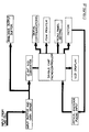
- Figure 1 is a schematic side view of a simple mechanical form of the device and Figure 2 is an end view.
- Figure 3 is a schematic view of a form of device with microprocessor controls and digital display.
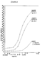
- Figure 4 is a block diagram of such a device, Figures 5, 6 and 8 are graphical results using the method of this invention and Figure 7 is a graphical result for a prior art method.
- the device comprises a base 9, two axial supports 11 and 12 which support clamping heads 13 and 14 on a common axis 10.
- the clamping heads 13 and 14 are both rotatable in a plane perpendicular to the axis 10.
- the sample to be tested is held with its longitudinal axis aligned with axis 10 in the clamps 13 and 14. Screws 15 enable clamps 13 and 14 to be tightened to effectively grip the sample 21 without producing out of balance in the clamps.
- Clamp 13 can be fixed in position by preventing rotation of the connecting clamp 13 about the axis 10 relative to the axial support 11 by way of adjustment screw 20.
- Clamp 14 which is on a common axis with the wheel 16 is finely balanced to freely turn its axis.
- the wheel 16 can have a wire 17 wound on to it to support a weight.
- the instrument can be mounted on a force measuring instrument via support 19 and the wire 17 can also be connected.
- the wheel 16 is marked with an angular scale 18 and the marker 22 is used to align the axis with the beginning of the scale.
- a specimen board is cut into test pieces of normal test size 100mm by 25mm.
- a test piece 21 is then mounted into the clamp and the clamps 13 and 14 tightened.
- the clamps are rotated to bring the beginning of the scale 18 into alignment with marker 22 and the clamp 13 is fixed by tightening screw 20.
- the embodiment shown in figure 3 comprises a base 30 supporting the instrument which comprises
- a cam and microswitch 40 are located between the sample jaw 39 and rotary encoder 38.
- the covers 41 enclose the stationary parts of the apparatus so that only the sample 42 and the jaws 33 and 39 are exposed.
- This form of the testing device is microprocessor controlled as illustrated in the block diagram of Figure 4. Inputs are received from the load cell and the rotary encoder to measure force and angular displacement. Desired loads or angular deflections for samples can be keyed in. Readouts of force or displacement are shown on a LCD display panel. The electronic circuitry and the programming of the microprocessor are conventional.
- Either apparatus can be operated in a number of modes to measure:
- the twisting movement (M) at the jaws 13, 14 is proportional to the angle of jaw rotation (O) and the MD Shear stiffness (S) of the corrugated sample.
- Figure 6 shows the load readings for shear stiffness measured in Milli Newton metres in accordance with the present invention and Figure 7 shows the thickness of the same board.
- Figure 8 illustrates another application of the present invention in assessing damage for quality control purposes across the corrugator machine.
Abstract
Description
- This invention relates to an instrument and method for testing paperboard products and assessing the structural properties of paperboard during manufacture. In particular, this invention is concerned with measuring shear stiffness of the corrugating medium in corrugated paperboard.
- Measurement of shear stiffness provides an important parameter in defining the structural properties of paperboard and for determining the strength of corrugated paperboard panels for end use applications.
- Various methods have been investigated for measuring the core (medium) shear stiffness of corrugated board. The methods currently used are:
- 1) Three point beam test at various spans;
- 2) Direct shear.
- The first of these methods requires a lot of testing and for relatively stiff cores can give low results due to local buckling at the point of application of the central load.
- The second method requires attaching the specimen to a rigid backing strip by gluing or some other means. This procedure is tedious and the results from this method are very variable due to the very small deflections involved during measurement.
- It is an object of this invention to provide a simpler method of determining shear stiffness using a few samples.
- In another aspect this invention relates to a method of asssessing damage to corrugated board mediums during printing and box manufacture.
- At present the recommended method of assessing medium damage is by thickness measurements of the board in accordance with 1987 Tappi Report 30304-11.
- This invention provides a more accurate measure of medium damage by measuring medium shear stiffness in the machine direction.
- US-A-2843390 discloses a fluid operated clamping jaw which could be used in a torsion testing machine employing a method of determining the shear stiffness of a material as an aid in processing the material, comprising placing a sample of the material between two clamps and subjecting the sample to a twisting force.
- According to the present invention the material is corrugated paperboard, one or more of the following tests are conducted: a) measuring the initial angle of twist for a given load; or b) measuring the change in the angle of twist over time under a constant load; or c) measuring the force required to achieve an initial angle of twist; or d) measuring the change over time in the force required to maintain a given angle of twist; and the shear stiffness S is determined according to the equation


- By twisting a sample shear strains are produced in the core.
- The measurements can also be made with varying conditions of humidity and varying degrees of crush applied to the sample to determine performance of the medium under varying conditions.
- By assessing a range of products it is possible to establish a scale of performance with small deflections for a given force or large forces to achieve a given deflection being the desirable characteristics of better quality paperboards.
- The device useful in carrying out the method of this invention essentially comprises a pair of axially aligned clamps at least one clamp being pivoted for rotation in a plane perpendicular to the alignment axis and means for measuring the force applied to rotate one of said clamps and means for measuring the angle of rotation.
- The device can be manually operable with the addition of weights to a lever arm or the like to produce rotation of one clamp relative to the other. Alternatively, the device can be mounted on a force measuring instrument such as an INSTRON and the rotatable clamp moved to a constant maximum angle of rotation with measurement of the force required to achieve that. Such a measurement can be repeated serially to determine the performance of the sample under such repetitive twist over time.
- The method of this invention is used to measure shear stiffness in the Machine Direction (MD) of corrugated board. This means that the flutes are visible along the longside of the sample. This measure of MD shear measures approximately 80% of the required property and although not a pure measurement has great experimental advantages.
- The various types of readings which can be gained provide a number of means of assessing the decay in shear stiffness over time as well as an initial assessment of shear stiffness. This enables a consistent comparison to be made of the quality of paperboard being produced or being utilised.
- Thus, it con be used not only to assess the quality of board at a particular time but to also assess its likely behaviour in various humidities or after crushing to varying degrees.
- A preferred form of this invention will now be described with reference to the drawings in which Figure 1 is a schematic side view of a simple mechanical form of the device and Figure 2 is an end view. Figure 3 is a schematic view of a form of device with microprocessor controls and digital display. Figure 4 is a block diagram of such a device, Figures 5, 6 and 8 are graphical results using the method of this invention and Figure 7 is a graphical result for a prior art method.
- The device comprises a base 9, two
axial supports clamping heads common axis 10. Theclamping heads axis 10. - The sample to be tested is held with its longitudinal axis aligned with
axis 10 in theclamps Screws 15 enableclamps sample 21 without producing out of balance in the clamps. -
Clamp 13 can be fixed in position by preventing rotation of the connectingclamp 13 about theaxis 10 relative to theaxial support 11 by way ofadjustment screw 20. -
Clamp 14 which is on a common axis with thewheel 16 is finely balanced to freely turn its axis. Thewheel 16 can have a wire 17 wound on to it to support a weight. - Alternatively, the instrument can be mounted on a force measuring instrument via
support 19 and the wire 17 can also be connected. Thewheel 16 is marked with anangular scale 18 and themarker 22 is used to align the axis with the beginning of the scale. - To carry out testing, a specimen board is cut into test pieces of normal test size 100mm by 25mm.
- A
test piece 21 is then mounted into the clamp and theclamps scale 18 into alignment withmarker 22 and theclamp 13 is fixed by tighteningscrew 20. - The embodiment shown in figure 3 comprises a
base 30 supporting the instrument which comprises - (i) a
load cell 31 and its associated bearinghousing 32 for thesample jaws 33. - ii) an
electric motor 35 and associatedgearbox 36 connected via thesoft coupling 37 to therotary encoder 38 to which thesample jaws 39 are connected. - A cam and
microswitch 40 are located between thesample jaw 39 androtary encoder 38. Thecovers 41 enclose the stationary parts of the apparatus so that only thesample 42 and thejaws - This form of the testing device is microprocessor controlled as illustrated in the block diagram of Figure 4. Inputs are received from the load cell and the rotary encoder to measure force and angular displacement. Desired loads or angular deflections for samples can be keyed in. Readouts of force or displacement are shown on a LCD display panel. The electronic circuitry and the programming of the microprocessor are conventional.
- Either apparatus can be operated in a number of modes to measure:
- initial deflection under constant load
- initial load for a constant deflection and
- variations of these over time in either fixed or varying atmospheric and humidity conditions.
- The twisting movement (M) at the
jaws jaws 

Figure 5 shows the average performance of samples of waxed, unwaxed, unprinted and unwaxed printed boards over time under constant stress. The graphs illustrate the increase in deflection over time and demonstrate the superior shear stiffness of the waxed boards. - Comparative tests have been carried out to compare the industry recommended method of measuring medium damage with the method according to this invention.
- Tests were carried out on samples from corrugated board used in making boxes in accordance with the following specifications:


- Figure 6 shows the load readings for shear stiffness measured in Milli Newton metres in accordance with the present invention and Figure 7 shows the thickness of the same board.
- A comparison of Figures 6 and 7 clearly shows that a much better measure of the board damage at various moisture levels in the board can be ascertained from Shear Stiffness measurements than from thickness. This is probably due in part to thickness recovery after damage has occurred.
- Figure 8 illustrates another application of the present invention in assessing damage for quality control purposes across the corrugator machine.
- By measuring the medium shear at various distances from the operator side of the corrugator a profile of the machine's effect on board quality is shown for different corrugator speeds.
- The information derived from tests of the sort illustrated in Figures 6 and 8 enable operators to adjust machine speed or other operating conditions to maintain desired structural properties in the corrugated board.
- Although the measurement of shear stiffness by this method is not a "pure" measurement it has experimental advantages. The apparatus is simple to use and requires minimal sample preparation.
Claims (4)
- A method of determining the shear stiffness of a material as an aid in processing the material, comprising placing a sample (21) of the material between two clamps (13,14) and subjecting the sample (21) to a twisting force characterised in that the material is corrugated paperboard and in that one or more of the following tests are conducted: a) measuring the initial angle of twist for a given load; or b) measuring the change in the angle of twist over time under a constant load; or c) measuring the force required to achieve an initial angle of twist; or d) measuring the change over time in the force required to maintain a given angle of twist; and in that the shear stiffness, S, is determined according to the equation


- A method according to claim 1 characterised in that the sample (21) is rectangular in shape and is held lengthwise by said clamps (13,14) located at each end and in that one end only is subjected to a twisting force.
- A method according to claim 2 characterised in that the clamps (13,14) are axially aligned and one clamp (14) is pivoted for rotation in a plane perpendicular to the alignment axis (10).
- A method according to claim 3 characterised in that the force needed to rotate said one clamp (14) is measured and the angle of rotation of said one clamp (14) is also measured.
Priority Applications (1)
| Application Number | Priority Date | Filing Date | Title |
|---|---|---|---|
| AT89300720T ATE102350T1 (en) | 1988-02-10 | 1989-01-26 | SHEAR STIFFNESS MEASUREMENT PROCEDURE. |
Applications Claiming Priority (2)
| Application Number | Priority Date | Filing Date | Title |
|---|---|---|---|
| AUPI667988 | 1988-02-10 | ||
| AU6679/88 | 1988-02-10 |
Publications (3)
| Publication Number | Publication Date |
|---|---|
| EP0328272A2 EP0328272A2 (en) | 1989-08-16 |
| EP0328272A3 EP0328272A3 (en) | 1990-10-03 |
| EP0328272B1 true EP0328272B1 (en) | 1994-03-02 |
Family
ID=3772799
Family Applications (1)
| Application Number | Title | Priority Date | Filing Date |
|---|---|---|---|
| EP89300720A Expired - Lifetime EP0328272B1 (en) | 1988-02-10 | 1989-01-26 | Shear stiffness measuring method |
Country Status (8)
| Country | Link |
|---|---|
| US (1) | US4958522A (en) |
| EP (1) | EP0328272B1 (en) |
| JP (1) | JPH01250036A (en) |
| AT (1) | ATE102350T1 (en) |
| CA (1) | CA1322469C (en) |
| DE (1) | DE68913317T2 (en) |
| ES (1) | ES2049808T3 (en) |
| NZ (1) | NZ227650A (en) |
Families Citing this family (37)
| Publication number | Priority date | Publication date | Assignee | Title |
|---|---|---|---|---|
| JPH03293539A (en) * | 1990-04-11 | 1991-12-25 | Kao Corp | Hair nature measuring apparatus |
| US5379648A (en) * | 1993-07-26 | 1995-01-10 | Sonoco Products Company | Method and apparatus for testing chew-out strength of paperboard core |
| US5567884A (en) * | 1994-03-09 | 1996-10-22 | International Business Machines Corporation | Circuit board assembly torsion tester and method |
| US5736646A (en) * | 1994-03-09 | 1998-04-07 | International Business Machines Corporation | Circuit board assembly torsion tester and method |
| US5447072A (en) * | 1994-07-27 | 1995-09-05 | International Business Machines Corporation | Torsional tester for circuit cards |
| US5460052A (en) * | 1994-07-28 | 1995-10-24 | University Of Massachusetts Lowell | Apparatus and method for measuring composite interface properties |
| DE4436628C1 (en) * | 1994-10-13 | 1996-04-11 | Koenig & Bauer Albert Ag | Device for measuring a deflection of a cylinder of a rotary printing press |
| US5511432A (en) * | 1995-04-10 | 1996-04-30 | Holmes; William C. | Holder for corrugated paperboard test specimen during edge compression test |
| SE506383C2 (en) * | 1996-04-24 | 1997-12-08 | Anders Loennoe | Device for measuring shear in the core of a sandwich construction |
| US5838568A (en) * | 1996-06-28 | 1998-11-17 | International Business Machines Corporation | Heated circuit assembly tester and method |
| US6094980A (en) * | 1998-10-09 | 2000-08-01 | Larson Systems Inc. | Torsion spring tester |
| US6289743B1 (en) | 1999-03-31 | 2001-09-18 | Craig Norton | Shoe testing apparatus and method of use |
| AUPQ515100A0 (en) * | 2000-01-19 | 2000-02-10 | Amcor Limited | Measurement apparatus and technique for properties of board product |
| EP1191304B1 (en) * | 2000-09-20 | 2011-11-16 | Bridgestone Corporation | Hole center detecting apparatus, straightness measuring apparatus and residual torsion measuring apparatus |
| US6684167B2 (en) | 2001-05-15 | 2004-01-27 | International Paper Company | Method and apparatus for measuring energy consumed during plastic deformation in multi-ply board systems |
| US6732057B2 (en) | 2001-05-15 | 2004-05-04 | International Paper Company | Methods for engineering and manufacturing score-line-crack-resistant linerboard |
| US6701098B2 (en) | 2002-02-20 | 2004-03-02 | Hewlett-Packard Development Company, L.P. | Automatically determining heat-conductive properties of print media |
| NZ534785A (en) * | 2004-08-19 | 2007-01-26 | Nz Forest Res Inst Ltd | Method and apparatus for testing of shear stiffness in board |
| WO2007033410A1 (en) * | 2005-09-21 | 2007-03-29 | Messmer Instruments Ltd | Method and apparatus for measuring properties of board products |
| JP2009540301A (en) * | 2006-06-09 | 2009-11-19 | ザ ティムケン カンパニー | Method and apparatus for shear strain test of strain sensor |
| US7690265B2 (en) * | 2007-03-07 | 2010-04-06 | Pratt & Whitney Rocketdyne, Inc. | Constant moment testing device for elongated members |
| US8286499B2 (en) | 2008-07-19 | 2012-10-16 | The Boeing Company | Method and apparatus for testing attachment joints |
| CN102680332B (en) * | 2012-05-28 | 2015-01-28 | 盛利维尔(中国)新材料技术有限公司 | Instrument for testing torsion resistance of superfine steels wires |
| CN103018593A (en) * | 2012-11-29 | 2013-04-03 | 无锡众望四维科技有限公司 | Connection performance testing device for apparatus with rotationally connected power line |
| CN103018024A (en) * | 2012-12-03 | 2013-04-03 | 奇瑞汽车股份有限公司 | Method for evaluating torsional rigidity |
| CN103196757B (en) * | 2013-04-25 | 2015-04-08 | 哈尔滨工业大学 | Device and method for composite material member bar torsion experiment |
| CN103499499B (en) * | 2013-06-19 | 2015-12-02 | 吉林大学 | Bilateral power original position micro-torsion material mechanical performance tester under a kind of microcosmic visual field |
| CN103698231B (en) * | 2013-12-20 | 2016-08-17 | 中天科技海缆有限公司 | A kind of torsional rigidity test device |
| CN103969106B (en) * | 2014-04-15 | 2016-03-02 | 上海理工大学 | Tension-torsion composite fatigue testing table |
| CN104237029B (en) * | 2014-08-28 | 2016-09-07 | 山东方圆建筑工程检测中心 | A kind of heat insulated shape bar of aluminum alloy torsional property test device |
| CN104792630A (en) * | 2015-04-27 | 2015-07-22 | 中国直升机设计研究所 | Test method for testing torsional rigidity of flexible beam |
| CN106680117B (en) * | 2016-06-02 | 2019-07-09 | 山东大学(威海) | Plate torsion testing machine |
| CN108106863B (en) * | 2016-11-25 | 2019-08-09 | 上海中国弹簧制造有限公司 | Bearing spring torsional fatigue of wire test method |
| CN108801809B (en) * | 2018-07-02 | 2019-03-19 | 广东精迅里亚特种线材有限公司 | A kind of aluminium bar production torsion testing machine and application method |
| JP2021024643A (en) * | 2019-08-09 | 2021-02-22 | リケンテクノス株式会社 | Wrap film product |
| CN111122352A (en) * | 2019-11-28 | 2020-05-08 | 浙江华电器材检测研究所有限公司 | Torsion test device for charging interface connecting cable |
| CN113447371B (en) * | 2021-06-10 | 2022-04-22 | 中南大学 | High-precision testing method for equivalent statics torsion parameters of dot matrix plates |
Family Cites Families (13)
| Publication number | Priority date | Publication date | Assignee | Title |
|---|---|---|---|---|
| US3122915A (en) * | 1964-03-03 | Haller | ||
| DE96334C (en) * | ||||
| US1559466A (en) * | 1924-03-19 | 1925-10-27 | Schopper Alfred | Apparatus for testing the strength of pasteboard, cardboard, and the like |
| US2044411A (en) * | 1936-02-17 | 1936-06-16 | Jr Leonce Vaughan | Device for measuring stiffness of sheet material |
| US2765655A (en) * | 1954-08-17 | 1956-10-09 | Scott Lester | Torsion spring testing devices |
| US2843390A (en) * | 1954-12-23 | 1958-07-15 | American Machine & Metals | Fluid operated testing machines |
| US2960863A (en) * | 1957-01-11 | 1960-11-22 | Gertrude G Weiss | Torque-rotation recorder |
| US3675475A (en) * | 1970-05-25 | 1972-07-11 | Sperry Rand Corp | Material testing device for the continuous measurement of stress relaxation |
| SU449281A1 (en) * | 1972-07-20 | 1974-11-05 | Войсковая Часть 14262 | Device for testing torsions when they are eccentrically secured |
| SU640178A1 (en) * | 1977-07-25 | 1978-12-30 | Ленинградская Ордена Ленина Лесотехническая Академия Им. С.М.Кирова | Device for measuring viscous-elastic characteristics of pulp-and-paper materials |
| DE2745182C3 (en) * | 1977-10-07 | 1980-04-30 | Feldmuehle Ag, 4000 Duesseldorf | Device for determining the flexural rigidity of cardboard and paperboard |
| JPS6025446Y2 (en) * | 1980-06-30 | 1985-07-31 | 株式会社淀川製鋼所 | Mounting structure of roof panels in assembled warehouses, etc. |
| US4482174A (en) * | 1980-09-15 | 1984-11-13 | Lokring | Apparatus and method for making a tube connection |
-
1989
- 1989-01-18 NZ NZ227650A patent/NZ227650A/en unknown
- 1989-01-26 AT AT89300720T patent/ATE102350T1/en not_active IP Right Cessation
- 1989-01-26 EP EP89300720A patent/EP0328272B1/en not_active Expired - Lifetime
- 1989-01-26 DE DE68913317T patent/DE68913317T2/en not_active Expired - Fee Related
- 1989-01-26 ES ES89300720T patent/ES2049808T3/en not_active Expired - Lifetime
- 1989-01-30 CA CA000589592A patent/CA1322469C/en not_active Expired - Fee Related
- 1989-02-06 US US07/307,411 patent/US4958522A/en not_active Expired - Lifetime
- 1989-02-10 JP JP1030084A patent/JPH01250036A/en active Pending
Also Published As
| Publication number | Publication date |
|---|---|
| DE68913317T2 (en) | 1994-06-09 |
| EP0328272A3 (en) | 1990-10-03 |
| ATE102350T1 (en) | 1994-03-15 |
| US4958522A (en) | 1990-09-25 |
| EP0328272A2 (en) | 1989-08-16 |
| NZ227650A (en) | 1990-06-26 |
| DE68913317D1 (en) | 1994-04-07 |
| CA1322469C (en) | 1993-09-28 |
| ES2049808T3 (en) | 1994-05-01 |
| JPH01250036A (en) | 1989-10-05 |
Similar Documents
| Publication | Publication Date | Title |
|---|---|---|
| EP0328272B1 (en) | Shear stiffness measuring method | |
| US5574227A (en) | Paper board crease force measuring device | |
| US20030136199A1 (en) | Measurement apparatus and technique for properties of board products | |
| AU603502B2 (en) | Shear stiffness tester | |
| US5048347A (en) | Method for testing corrugated medium | |
| CA2217715C (en) | Method and apparatus of testing board product | |
| US6219141B1 (en) | Method and apparatus for measuring waviness of paper | |
| CN114577717A (en) | Coating adhesive force testing device with controllable drawing angle | |
| US6684167B2 (en) | Method and apparatus for measuring energy consumed during plastic deformation in multi-ply board systems | |
| JPH0357418B2 (en) | ||
| Chalmers | A new method for determining the shear stiffness of corrugated board | |
| Fachet et al. | Present Practices in Tension Testing of Paper in Industry | |
| AU711177B2 (en) | Method and apparatus of testing board product | |
| JPS62127643A (en) | Analysis of scoring rule characteristic of carton | |
| Hardacker | Instrument and specimen shape for biaxial testing of paper | |
| Bergqvist | Use of extensometers with spherically pointed pin ends for accurate determination of material qualities | |
| AU692765B2 (en) | Force testing machine | |
| AU781022B2 (en) | Measurement apparatus and technique for properties of board products | |
| SU1350482A1 (en) | Method of determining normal and tangential stresses along preset direction at check points of object made of sheet anisotropic material | |
| KR20180081015A (en) | An Apparatus for Measuring a Torsion Property of a Material | |
| Tester | Standard Test Method for Folding Endurance of Paper by the Schopper Tester1 | |
| Armstrong et al. | Measurement of Large Cylinders Where Access is Restricted—A Novel Approach |
Legal Events
| Date | Code | Title | Description |
|---|---|---|---|
| PUAI | Public reference made under article 153(3) epc to a published international application that has entered the european phase |
Free format text: ORIGINAL CODE: 0009012 |
|
| AK | Designated contracting states |
Kind code of ref document: A2 Designated state(s): AT BE CH DE ES FR GB GR IT LI LU NL SE |
|
| PUAL | Search report despatched |
Free format text: ORIGINAL CODE: 0009013 |
|
| AK | Designated contracting states |
Kind code of ref document: A3 Designated state(s): AT BE CH DE ES FR GB GR IT LI LU NL SE |
|
| 17P | Request for examination filed |
Effective date: 19901214 |
|
| 17Q | First examination report despatched |
Effective date: 19920630 |
|
| RAP1 | Party data changed (applicant data changed or rights of an application transferred) |
Owner name: AMCOR LIMITED |
|
| GRAA | (expected) grant |
Free format text: ORIGINAL CODE: 0009210 |
|
| ITF | It: translation for a ep patent filed |
Owner name: BARZANO' E ZANARDO MILANO S.P.A. |
|
| AK | Designated contracting states |
Kind code of ref document: B1 Designated state(s): AT BE CH DE ES FR GB GR IT LI LU NL SE |
|
| REF | Corresponds to: |
Ref document number: 102350 Country of ref document: AT Date of ref document: 19940315 Kind code of ref document: T |
|
| REF | Corresponds to: |
Ref document number: 68913317 Country of ref document: DE Date of ref document: 19940407 |
|
| ET | Fr: translation filed | ||
| REG | Reference to a national code |
Ref country code: ES Ref legal event code: FG2A Ref document number: 2049808 Country of ref document: ES Kind code of ref document: T3 |
|
| REG | Reference to a national code |
Ref country code: GR Ref legal event code: FG4A Free format text: 3012005 |
|
| PLBE | No opposition filed within time limit |
Free format text: ORIGINAL CODE: 0009261 |
|
| STAA | Information on the status of an ep patent application or granted ep patent |
Free format text: STATUS: NO OPPOSITION FILED WITHIN TIME LIMIT |
|
| EAL | Se: european patent in force in sweden |
Ref document number: 89300720.3 |
|
| 26N | No opposition filed | ||
| REG | Reference to a national code |
Ref country code: FR Ref legal event code: CA |
|
| REG | Reference to a national code |
Ref country code: GB Ref legal event code: IF02 |
|
| PGFP | Annual fee paid to national office [announced via postgrant information from national office to epo] |
Ref country code: GR Payment date: 20041216 Year of fee payment: 17 |
|
| PGFP | Annual fee paid to national office [announced via postgrant information from national office to epo] |
Ref country code: NL Payment date: 20050103 Year of fee payment: 17 |
|
| PGFP | Annual fee paid to national office [announced via postgrant information from national office to epo] |
Ref country code: SE Payment date: 20050107 Year of fee payment: 17 |
|
| PGFP | Annual fee paid to national office [announced via postgrant information from national office to epo] |
Ref country code: FR Payment date: 20050110 Year of fee payment: 17 |
|
| PGFP | Annual fee paid to national office [announced via postgrant information from national office to epo] |
Ref country code: AT Payment date: 20050112 Year of fee payment: 17 |
|
| PGFP | Annual fee paid to national office [announced via postgrant information from national office to epo] |
Ref country code: DE Payment date: 20050120 Year of fee payment: 17 |
|
| PGFP | Annual fee paid to national office [announced via postgrant information from national office to epo] |
Ref country code: GB Payment date: 20050126 Year of fee payment: 17 |
|
| PGFP | Annual fee paid to national office [announced via postgrant information from national office to epo] |
Ref country code: CH Payment date: 20050127 Year of fee payment: 17 |
|
| PGFP | Annual fee paid to national office [announced via postgrant information from national office to epo] |
Ref country code: LU Payment date: 20050201 Year of fee payment: 17 |
|
| PGFP | Annual fee paid to national office [announced via postgrant information from national office to epo] |
Ref country code: ES Payment date: 20050211 Year of fee payment: 17 |
|
| PGFP | Annual fee paid to national office [announced via postgrant information from national office to epo] |
Ref country code: BE Payment date: 20050419 Year of fee payment: 17 |
|
| PG25 | Lapsed in a contracting state [announced via postgrant information from national office to epo] |
Ref country code: GB Free format text: LAPSE BECAUSE OF NON-PAYMENT OF DUE FEES Effective date: 20060126 Ref country code: AT Free format text: LAPSE BECAUSE OF NON-PAYMENT OF DUE FEES Effective date: 20060126 |
|
| PG25 | Lapsed in a contracting state [announced via postgrant information from national office to epo] |
Ref country code: SE Free format text: LAPSE BECAUSE OF NON-PAYMENT OF DUE FEES Effective date: 20060127 Ref country code: ES Free format text: LAPSE BECAUSE OF NON-PAYMENT OF DUE FEES Effective date: 20060127 |
|
| PG25 | Lapsed in a contracting state [announced via postgrant information from national office to epo] |
Ref country code: LU Free format text: LAPSE BECAUSE OF NON-PAYMENT OF DUE FEES Effective date: 20060131 Ref country code: LI Free format text: LAPSE BECAUSE OF NON-PAYMENT OF DUE FEES Effective date: 20060131 Ref country code: FR Free format text: LAPSE BECAUSE OF NON-PAYMENT OF DUE FEES Effective date: 20060131 Ref country code: CH Free format text: LAPSE BECAUSE OF NON-PAYMENT OF DUE FEES Effective date: 20060131 Ref country code: BE Free format text: LAPSE BECAUSE OF NON-PAYMENT OF DUE FEES Effective date: 20060131 |
|
| PGFP | Annual fee paid to national office [announced via postgrant information from national office to epo] |
Ref country code: IT Payment date: 20060131 Year of fee payment: 18 |
|
| PG25 | Lapsed in a contracting state [announced via postgrant information from national office to epo] |
Ref country code: NL Free format text: LAPSE BECAUSE OF NON-PAYMENT OF DUE FEES Effective date: 20060801 Ref country code: DE Free format text: LAPSE BECAUSE OF NON-PAYMENT OF DUE FEES Effective date: 20060801 |
|
| REG | Reference to a national code |
Ref country code: CH Ref legal event code: PL |
|
| EUG | Se: european patent has lapsed | ||
| GBPC | Gb: european patent ceased through non-payment of renewal fee |
Effective date: 20060126 |
|
| NLV4 | Nl: lapsed or anulled due to non-payment of the annual fee |
Effective date: 20060801 |
|
| REG | Reference to a national code |
Ref country code: FR Ref legal event code: ST Effective date: 20060929 |
|
| REG | Reference to a national code |
Ref country code: ES Ref legal event code: FD2A Effective date: 20060127 |
|
| BERE | Be: lapsed |
Owner name: *AMCOR LTD Effective date: 20060131 |
|
| PG25 | Lapsed in a contracting state [announced via postgrant information from national office to epo] |
Ref country code: GR Free format text: LAPSE BECAUSE OF NON-PAYMENT OF DUE FEES Effective date: 20060802 |
|
| PG25 | Lapsed in a contracting state [announced via postgrant information from national office to epo] |
Ref country code: IT Free format text: LAPSE BECAUSE OF NON-PAYMENT OF DUE FEES Effective date: 20070126 |