EP0327525B1 - High-pressure flexible seat valve trim - Google Patents
High-pressure flexible seat valve trim Download PDFInfo
- Publication number
- EP0327525B1 EP0327525B1 EP89870021A EP89870021A EP0327525B1 EP 0327525 B1 EP0327525 B1 EP 0327525B1 EP 89870021 A EP89870021 A EP 89870021A EP 89870021 A EP89870021 A EP 89870021A EP 0327525 B1 EP0327525 B1 EP 0327525B1
- Authority
- EP
- European Patent Office
- Prior art keywords
- seal
- valve
- seal ring
- wall
- deformable
- Prior art date
- Legal status (The legal status is an assumption and is not a legal conclusion. Google has not performed a legal analysis and makes no representation as to the accuracy of the status listed.)
- Expired - Lifetime
Links
Images

Classifications
-
- F—MECHANICAL ENGINEERING; LIGHTING; HEATING; WEAPONS; BLASTING
- F16—ENGINEERING ELEMENTS AND UNITS; GENERAL MEASURES FOR PRODUCING AND MAINTAINING EFFECTIVE FUNCTIONING OF MACHINES OR INSTALLATIONS; THERMAL INSULATION IN GENERAL
- F16K—VALVES; TAPS; COCKS; ACTUATING-FLOATS; DEVICES FOR VENTING OR AERATING
- F16K1/00—Lift valves or globe valves, i.e. cut-off apparatus with closure members having at least a component of their opening and closing motion perpendicular to the closing faces
- F16K1/32—Details
- F16K1/34—Cutting-off parts, e.g. valve members, seats
- F16K1/42—Valve seats
- F16K1/427—Attachment of the seat to the housing by one or more additional fixing elements
Definitions
- This invention relates to fluid valves and more particularly to fluid sealing apparatus in fluid valves for providing a reliable shutoff of high pressure fluid.
- valves having reliable valve fluid sealing components (i.e., valve trim) which is required to provide a tight fluid shutoff for long periods of time.
- valve trim reliable valve fluid sealing components
- Special problems arise in such environments in view of the high pressures and the high temperatures which can range from about 250° to about 450° Fahrenheit (121° to about 232° Celsius).
- valves for such environments include complex shaped valve trim components which lead to costly manufacturing and time consuming and costly replacement during normal valve maintenance.
- fluid valves employ metal-to-metal seating for all general applications over a wide range of pressure drops and temperatures, and metal-to-TFE (tetrafluoroethylene) seating for more stringent shutoff requirements.
- metal-to-metal seating for all general applications over a wide range of pressure drops and temperatures
- metal-to-TFE tetrafluoroethylene
- An example of such a standard and optional seating is available in a design ES valve body made by Fisher Controls International, Inc.
- This commercially available fluid valve includes a valve trim having a valve plug seating against a seal ring formed of tetrafluoroethylene (TFE) which is located in a metal seal ring housing and held in place by a metal disk retainer. While such a configuration is acceptable for most conditions, it is desired to provide a fluid valve with improved valve trim components for reliable use under stringent high pressure and high temperature conditions.
- US-A-3 809 362 there is described an improved valve trim for high pressure fluid valve use, wherein a deformable plastic insert seat ring is mounted on a seat ring housing and held in place by a seat ring retainer.
- the seat ring retainer includes a series of inwardly and outwardly formed surfaces facing opposite similarly shaped seat ring housing surfaces, and with the deformable plastic seat ring having a similar series of surfaces and located between the retainer and the housing.
- the valve plug compresses the deformable seat ring to stress the ring above the yield point and cause it to act like a liquid to enable the seat ring to deform and displace so as to establish a plastic-to-metal hydrostatic seal.
- US-A-3 027 911 discloses a safety relief valve comprising a valve plug with an outwardly extending plug seating surface, a deformable, resilient seal ring and a seal ring housing located axially in line with said valve plug, said seal ring housing having an annular cavity for receiving said deformable, resilient seal, said cavity being formed by a flexible metal seat which comprises a flexible metal lip protruding from the seat ring housing.
- the resilient seal ring is arranged in the movable plug/plug guide assembly.
- the flexible metal lip contacts the valve seating surface and the seat flexes the flexible metal lip inwardly to cause the resilient seal ring to flow outwardly and contact the valve seating surface to form a plastic compression seal.
- the plug and the plug guide must be threadably engaged and properly adjusted to deform the annular seal ring e.g. to the shape shown in Figure 3.
- valve trim which is capable of reliable operation under high pressure, high temperature conditions. It is also desired to provide such a valve trim which is more easily manufactured and at less cost than presently available units and which can be more easily and readily maintained during normal valve maintenance.
- a fluid valve as defined in the claims.
- the valve includes a valve plug with an outwardly extending plug seating surface, a deformable seal ring of resilient material, a seal ring housing with a flexible metal seat for holding the deformable seal ring, and a metal seal retainer surrounding the flexible metal seat and the seal.
- the seal retainer has a closely matching contour to the seal ring so as to hold the seal ring tightly in place and so that as the valve plug closes and engages the flexible metal seat, one portion of the metal seat flexes radially outwardly to squeeze the deformable seal inwardly against the valve plug. Outward movement of the seal during flexing of the rigid metal seat is prevented by the closely matching contour of the metal seal retainer.
- This valve trim has the capability to produce a tight seal on assembly with no adjustment being required.
- the seal relaxes when the valve plug is opened and is squeezed inwardly against the valve plug to form a leak tight seal around the perimeter of the valve plug as the valve plug contacts the flexible metal seat.
- the plastic seal is preferably made of carbon-filled TFE, which allows repeated valve closings at temperatures up to 450° Fahrenheit (232° Celsius).
- a significantly advantageous feature of the present invention is that the fluid valve, and particularly the valve trim components are readily manufactured, assembled, and can easily be replaced during maintenance.
- the deformable plastic seal is merely inserted into the flexible metal seat and the seal retainer placed in position to surround both the seal and the flexible metal seat without any adjustment of the position of the components.
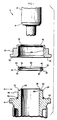
- FIG. 1 illustrates a set of valve trim components 10 for a high pressure fluid valve in accordance with an embodiment of the present invention.
- a valve plug 12 includes an outwardly extending plug seating surface 14.
- a seal ring housing 16 includes a flexible metal seat 18 at an axial end of the housing for containing a deformable seal 20 formed of a resilient material such as an elastomer, rubber, synthetic resin polymer, etc.
- seal 20 be formed of TFE or other synthetic resin polymer material.
- the flexible metal seat includes a cavity 22 which is formed and defined between an outer axially extending wall 24 and an inner axially extending wall 26.
- Wall 26 includes an extension portion projecting beyond cavity 22 and outer wall 24, and which extension portion ends in a thin, lip portion end 28.
- Wall 26 and lip portion end 28 are formed so that upon seating contact by valve plug seating surface 14, as shown in Figure 2, the lip portion will be flexed outwardly. It is preferred that the lip portion end has a small radius to define an arcuate surface 29 which contacts valve plug seating surface 14.
- Deformable seal 20 has a portion 30 adapted to fit within cavity 22, an outer trim portion 32 which extends slightly over an end 34 of outer wall 24; an inner portion 36 which extends slightly over lip portion end 28; and an contoured portion 40 which projects beyond cavity 22 and is adjacent to lip portion end 28.
- a rigid metal seal retainer 42 is adapted to surround the flexible metal seat and the deformable seal.
- retainer inner surface 44 is shaped similar to and closely matches the contour of seal ring housing surface 46
- retainer arcuate surface 48 is shaped similar to and closely matches the similar arcuate contour of outer surface 50 of the deformable seal.
- the closely matched contour surfaces of the retainer, seal and housing are formed with close dimensional tolerances so that there is a relatively snug fit between these components.
- seal retainer holds the seal in place with a closely matching contour when seal retainer bottom surface 52 abuttingly contacts a ledge 54 of the seal ring housing.
- O-ring 56 may be provided if desired as an additional seal between retainer 42 and housing 16.
- plug 12 In operation, during closing of the valve, plug 12 is moved towards seal ring housing 16 so that plug seating surface 14 seatingly engages in metal-to-metal sealing contact with flexible lip 28. As the valve plug closes against the metal lip, the lip flexes, thereby squeezing against the seal 20. However, in view of the closely matched contour between seal retainer 42 and the seal 20, seal 20 cannot move outwardly and instead is squeezed inwardly against valve plug seating surface 14. This provides a leak tight seal around the perimeter of the valve plug. Upon opening of the valve, plug 12 is moved away from the flexible metal seat and the seal relaxes.
- the deformable seal 20 preferably is made of carbon-filled TFE, so as to allow repeated closings of the valve at temperatures up to 450° Fahrenheit (232° Celsius). Other grades of plastic material could be substituted for different temperature requirements and fluids. It is to be understood that while the present invention has been described for use in high pressure valves, where the valve trim is required to provide tight shutoff for long periods of time, the invention may also be used on less demanding situations involving lower pressure differentials and lower temperatures such as gasses or chemicals.
- valve trim itself can also be used in a rotary valve.
- valve trim of the present invention could be adapted for use in a rotary type valve with an off-centered shaft that can rotate a valve plug into the trim seal, instead of merely sliding across the valve opening as in a normal ball valve configuration.
- the valve plug seating surface thus may be rotated into a flexible metal seat containing a deformable seal rigidly held in place by a surrounding metal seal retainer.
- a small seat portion may be flexed outwardly to squeeze the deformable seal inwardly against the rotary valve seating surface.
Landscapes
- Engineering & Computer Science (AREA)
- General Engineering & Computer Science (AREA)
- Mechanical Engineering (AREA)
- Lift Valve (AREA)
- Taps Or Cocks (AREA)
- Gasket Seals (AREA)
Description
- This invention relates to fluid valves and more particularly to fluid sealing apparatus in fluid valves for providing a reliable shutoff of high pressure fluid.
- In many applications, such as in power plants, high temperature boiler feedwater systems require fluid valves having reliable valve fluid sealing components (i.e., valve trim) which is required to provide a tight fluid shutoff for long periods of time. Special problems arise in such environments in view of the high pressures and the high temperatures which can range from about 250° to about 450° Fahrenheit (121° to about 232° Celsius).
- Presently available valves for such environments include complex shaped valve trim components which lead to costly manufacturing and time consuming and costly replacement during normal valve maintenance. Typically, fluid valves employ metal-to-metal seating for all general applications over a wide range of pressure drops and temperatures, and metal-to-TFE (tetrafluoroethylene) seating for more stringent shutoff requirements. An example of such a standard and optional seating is available in a design ES valve body made by Fisher Controls International, Inc. This commercially available fluid valve includes a valve trim having a valve plug seating against a seal ring formed of tetrafluoroethylene (TFE) which is located in a metal seal ring housing and held in place by a metal disk retainer. While such a configuration is acceptable for most conditions, it is desired to provide a fluid valve with improved valve trim components for reliable use under stringent high pressure and high temperature conditions.
- In US-A-3 809 362 there is described an improved valve trim for high pressure fluid valve use, wherein a deformable plastic insert seat ring is mounted on a seat ring housing and held in place by a seat ring retainer. The seat ring retainer includes a series of inwardly and outwardly formed surfaces facing opposite similarly shaped seat ring housing surfaces, and with the deformable plastic seat ring having a similar series of surfaces and located between the retainer and the housing. During valve closing, the valve plug compresses the deformable seat ring to stress the ring above the yield point and cause it to act like a liquid to enable the seat ring to deform and displace so as to establish a plastic-to-metal hydrostatic seal.
- US-A-3 027 911 discloses a safety relief valve comprising a valve plug with an outwardly extending plug seating surface, a deformable, resilient seal ring and a seal ring housing located axially in line with said valve plug, said seal ring housing having an annular cavity for receiving said deformable, resilient seal, said cavity being formed by a flexible metal seat which comprises a flexible metal lip protruding from the seat ring housing. The resilient seal ring is arranged in the movable plug/plug guide assembly. During valve closing , the flexible metal lip contacts the valve seating surface and the seat flexes the flexible metal lip inwardly to cause the resilient seal ring to flow outwardly and contact the valve seating surface to form a plastic compression seal. In this valve, the plug and the plug guide must be threadably engaged and properly adjusted to deform the annular seal ring e.g. to the shape shown in Figure 3.
- It is desired to provide a fluid valve having a valve trim which is capable of reliable operation under high pressure, high temperature conditions. It is also desired to provide such a valve trim which is more easily manufactured and at less cost than presently available units and which can be more easily and readily maintained during normal valve maintenance.
- In accordance with the present invention, there is provided a fluid valve as defined in the claims. The valve includes a valve plug with an outwardly extending plug seating surface, a deformable seal ring of resilient material, a seal ring housing with a flexible metal seat for holding the deformable seal ring, and a metal seal retainer surrounding the flexible metal seat and the seal. The seal retainer has a closely matching contour to the seal ring so as to hold the seal ring tightly in place and so that as the valve plug closes and engages the flexible metal seat, one portion of the metal seat flexes radially outwardly to squeeze the deformable seal inwardly against the valve plug. Outward movement of the seal during flexing of the rigid metal seat is prevented by the closely matching contour of the metal seal retainer.
- This valve trim has the capability to produce a tight seal on assembly with no adjustment being required. The seal relaxes when the valve plug is opened and is squeezed inwardly against the valve plug to form a leak tight seal around the perimeter of the valve plug as the valve plug contacts the flexible metal seat. The plastic seal is preferably made of carbon-filled TFE, which allows repeated valve closings at temperatures up to 450° Fahrenheit (232° Celsius).
- A significantly advantageous feature of the present invention is that the fluid valve, and particularly the valve trim components are readily manufactured, assembled, and can easily be replaced during maintenance. In particular, during assembly of the valve trim, the deformable plastic seal is merely inserted into the flexible metal seat and the seal retainer placed in position to surround both the seal and the flexible metal seat without any adjustment of the position of the components.
- The invention may be best understood by reference to the following description taken in conjunction with the accompanying drawings, in which like reference numerals identify like elements in the several figures and in which:
- Figure 1 is an expanded view illustrating a preferred embodiment of a set of valve trim components for a fluid valve in accordance with the principles of the present invention; and
- Figure 2 is a fragmentary sectional view of a valve including the assembled valve trim components as shown in Figure 1.
- Figure 1 illustrates a set of
valve trim components 10 for a high pressure fluid valve in accordance with an embodiment of the present invention. Avalve plug 12 includes an outwardly extendingplug seating surface 14. Aseal ring housing 16 includes aflexible metal seat 18 at an axial end of the housing for containing adeformable seal 20 formed of a resilient material such as an elastomer, rubber, synthetic resin polymer, etc. For high pressure applications it is preferred thatseal 20 be formed of TFE or other synthetic resin polymer material. - The flexible metal seat includes a
cavity 22 which is formed and defined between an outer axially extendingwall 24 and an inner axially extendingwall 26.Wall 26 includes an extension portion projecting beyondcavity 22 andouter wall 24, and which extension portion ends in a thin,lip portion end 28.Wall 26 andlip portion end 28 are formed so that upon seating contact by valveplug seating surface 14, as shown in Figure 2, the lip portion will be flexed outwardly. It is preferred that the lip portion end has a small radius to define anarcuate surface 29 which contacts valveplug seating surface 14. -
Deformable seal 20 has aportion 30 adapted to fit withincavity 22, anouter trim portion 32 which extends slightly over anend 34 ofouter wall 24; aninner portion 36 which extends slightly overlip portion end 28; and ancontoured portion 40 which projects beyondcavity 22 and is adjacent tolip portion end 28. - A rigid
metal seal retainer 42 is adapted to surround the flexible metal seat and the deformable seal. In particular, retainerinner surface 44 is shaped similar to and closely matches the contour of sealring housing surface 46, and retainerarcuate surface 48 is shaped similar to and closely matches the similar arcuate contour ofouter surface 50 of the deformable seal. In addition, the closely matched contour surfaces of the retainer, seal and housing are formed with close dimensional tolerances so that there is a relatively snug fit between these components. - Thus, with reference to Figure 2, it can be seen that when
seal 20 is placed in theflexible metal seat 18, the seal retainer holds the seal in place with a closely matching contour when sealretainer bottom surface 52 abuttingly contacts aledge 54 of the seal ring housing. O-ring 56 may be provided if desired as an additional seal betweenretainer 42 andhousing 16. - In operation, during closing of the valve,
plug 12 is moved towardsseal ring housing 16 so thatplug seating surface 14 seatingly engages in metal-to-metal sealing contact withflexible lip 28. As the valve plug closes against the metal lip, the lip flexes, thereby squeezing against theseal 20. However, in view of the closely matched contour betweenseal retainer 42 and theseal 20,seal 20 cannot move outwardly and instead is squeezed inwardly against valveplug seating surface 14. This provides a leak tight seal around the perimeter of the valve plug. Upon opening of the valve,plug 12 is moved away from the flexible metal seat and the seal relaxes. - The
deformable seal 20 preferably is made of carbon-filled TFE, so as to allow repeated closings of the valve at temperatures up to 450° Fahrenheit (232° Celsius). Other grades of plastic material could be substituted for different temperature requirements and fluids. It is to be understood that while the present invention has been described for use in high pressure valves, where the valve trim is required to provide tight shutoff for long periods of time, the invention may also be used on less demanding situations involving lower pressure differentials and lower temperatures such as gasses or chemicals. - In addition, while the present invention has been illustrated for use in a sliding stem valve, the valve trim itself can also be used in a rotary valve. As an example, the valve trim of the present invention could be adapted for use in a rotary type valve with an off-centered shaft that can rotate a valve plug into the trim seal, instead of merely sliding across the valve opening as in a normal ball valve configuration. The valve plug seating surface thus may be rotated into a flexible metal seat containing a deformable seal rigidly held in place by a surrounding metal seal retainer. A small seat portion may be flexed outwardly to squeeze the deformable seal inwardly against the rotary valve seating surface.
- The foregoing detailed description has been given for clearness of understanding only, and no unnecessary limitations should be understood therefrom, as modifications will be obvious to those skilled in the art.
Claims (9)
- A fluid valve for high pressure applications including a valve plug (12) with an outwardly extending plug seating surface (14), a deformable, resilient seal ring (20) and a seal ring housing (16) located axially in line with said valve plug, said seal ring housing having a cavity (22) for receiving said deformable, resilient seal ring (20), said cavity (22) being formed in a flexible metal seat (18),
characterized in that:
said seal ring housing cavity (22) is arranged at an axial end of said seal ring housing (16) and in that said flexible metal seat (18) includes an inner wall (26) projecting axially contiguous with and extending beyond said cavity (22) and ending in a lip portion end (28) for seating engagement contact with said valve plug seating surface (14);
said axially extending inner wall (26) and lip portion end (28) being dimensioned for flexible radial outward action upon urging of said valve plug seating surface (14) during seating engagement contact thereof;
said deformable, resilient seal ring (20) is adapted to fill said cavity (22) and including a seal portion (40) contoured to be axially disposed adjacent to said lip portion end (28) of said flexible metal seat (18);
a rigid metal seal retainer (42) is provided axially alignable with said valve plug (12) and said seal ring housing (16) and surrounding said flexible metal seat (18) and said seal ring (20);
said rigid metal seal retainer (42) including an interior portion (44) having a surface contour (48) substantially similar to the surface contour (50) of said contoured seal portion (40) to enable said contoured seal portion (40) to be squeezingly urged inwardly against said valve plug seating surface (14) in response to said flexible radial outward action of said inner wall (26) and lip portion end (28) during seating engagement by said valve plug seating surface. - The fluid valve of claim 1, wherein the metal seal retainer interior portion (44) and said contoured seal portion (40) having a substantially similar surface contour (48,50) also are formed with close dimensional tolerances.
- The fluid valve of claim 1 or 2, wherein said deformable seal ring (20) is formed of TFE or other synthetic resin polymer material.
- The fluid valve of any of claims 1 - 3, wherein said deformable seal ring (20) includes an inner rim portion (36) which extends over said lip portion end (28) of said inner wall (26).
- The fluid valve of any of claims 1 - 4, wherein said flexible metal seat (18) further includes an outer axially extending wall (24) opposite said inner wall (26) to define said cavity (22) there-between.
- The fluid valve of claim 5, wherein said inner wall (26) extends beyond said outer wall (24) in axial direction.
- The fluid valve of any of claims 5 - 6, wherein said deformable seal ring (20) includes an outer rim portion (32) which extends over said outer wall (24).
- The fluid valve of any of claims 1 - 7, wherein said lip portion end (28) includes an arcuate surface (29) for seating engagement contact with said valve plug seating surface (14).
- The fluid valve of any of claims 1 - 8, wherein said metal seal retainer interior portion (44) and said contoured seal portion (40) are formed with matching arcuate surface contours (48,50).
Applications Claiming Priority (2)
| Application Number | Priority Date | Filing Date | Title |
|---|---|---|---|
| US07/152,632 US4834338A (en) | 1988-02-05 | 1988-02-05 | High pressure flexible seat valve trim |
| US152632 | 1988-02-05 |
Publications (3)
| Publication Number | Publication Date |
|---|---|
| EP0327525A2 EP0327525A2 (en) | 1989-08-09 |
| EP0327525A3 EP0327525A3 (en) | 1990-07-25 |
| EP0327525B1 true EP0327525B1 (en) | 1994-08-10 |
Family
ID=22543722
Family Applications (1)
| Application Number | Title | Priority Date | Filing Date |
|---|---|---|---|
| EP89870021A Expired - Lifetime EP0327525B1 (en) | 1988-02-05 | 1989-02-01 | High-pressure flexible seat valve trim |
Country Status (7)
| Country | Link |
|---|---|
| US (1) | US4834338A (en) |
| EP (1) | EP0327525B1 (en) |
| JP (1) | JP2622412B2 (en) |
| AU (1) | AU610335B2 (en) |
| BR (1) | BR8900496A (en) |
| CA (1) | CA1312592C (en) |
| DE (1) | DE68917331T2 (en) |
Families Citing this family (8)
| Publication number | Priority date | Publication date | Assignee | Title |
|---|---|---|---|---|
| GB9017007D0 (en) * | 1990-08-02 | 1990-09-19 | Bernard Derek J C | Improvements to pre-charged pneumatic airguns |
| US6776360B2 (en) * | 2001-06-26 | 2004-08-17 | Spraying Systems Co. | Spray gun with improved needle shut-off valve sealing arrangement |
| US6840520B2 (en) | 2003-01-23 | 2005-01-11 | Fisher Controls International Llc | Valve plug seal assembly |
| CA2462334C (en) * | 2004-03-24 | 2012-10-09 | Yoursolarhome Inc. | Integrated thermal and photovoltaic solar collector and method for operation and mounting an array of solar collectors |
| US8413955B1 (en) * | 2009-10-02 | 2013-04-09 | Taylor Innovations, Llc | Resiliently supported valve seat assembly for a safety relief valve |
| US11519510B1 (en) * | 2021-07-08 | 2022-12-06 | Saudi Arabian Oil Company | Relief valve seal holder |
| CN116221416B (en) * | 2021-12-02 | 2025-07-25 | 盾安汽车热管理科技有限公司 | Electric valve |
| EP4565805B1 (en) * | 2022-08-01 | 2026-03-11 | Danfoss A/S | Valve with valve insert comprising two cylinders |
Family Cites Families (10)
| Publication number | Priority date | Publication date | Assignee | Title |
|---|---|---|---|---|
| DE78997C (en) * | J.MORAVETZ, Gratwein, Steiermark | Copper sealing ring for valves | ||
| US2060748A (en) * | 1934-08-31 | 1936-11-10 | Roberts Hardy | Valve mechanism |
| CH262061A (en) * | 1947-06-05 | 1949-06-15 | Motosacoche Sa | Sealing device. |
| US3027911A (en) * | 1958-08-27 | 1962-04-03 | Fluid Mechanics Inc | Plastic seal ring valve |
| US3131906A (en) * | 1960-11-17 | 1964-05-05 | Orbit Valve Co | Valve seat |
| FR83984E (en) * | 1962-06-18 | 1964-11-06 | Improvements to sealing gaskets for pressurized fluid pipe plugs with actuator | |
| US3327991A (en) * | 1965-01-07 | 1967-06-27 | Elvis D Wallace | Valve seat with resilient support member |
| US3318577A (en) * | 1965-05-24 | 1967-05-09 | George W Banks | High pressure valve having soft seating and balanced seal |
| US3809362A (en) * | 1972-03-13 | 1974-05-07 | Masoneilan Int Inc | High pressure soft seat valve |
| DE2424148C2 (en) * | 1974-05-17 | 1983-08-11 | Robert Bosch Gmbh, 7000 Stuttgart | Gas-tight valve for machines for the treatment of materials with high temperature and pressure surges |
-
1988
- 1988-02-05 US US07/152,632 patent/US4834338A/en not_active Expired - Fee Related
-
1989
- 1989-02-01 EP EP89870021A patent/EP0327525B1/en not_active Expired - Lifetime
- 1989-02-01 DE DE68917331T patent/DE68917331T2/en not_active Expired - Fee Related
- 1989-02-03 JP JP1024111A patent/JP2622412B2/en not_active Expired - Lifetime
- 1989-02-03 CA CA000590057A patent/CA1312592C/en not_active Expired - Fee Related
- 1989-02-03 BR BR898900496A patent/BR8900496A/en not_active IP Right Cessation
- 1989-02-03 AU AU29575/89A patent/AU610335B2/en not_active Ceased
Also Published As
| Publication number | Publication date |
|---|---|
| BR8900496A (en) | 1989-10-03 |
| AU610335B2 (en) | 1991-05-16 |
| EP0327525A3 (en) | 1990-07-25 |
| JP2622412B2 (en) | 1997-06-18 |
| JPH01224574A (en) | 1989-09-07 |
| US4834338A (en) | 1989-05-30 |
| DE68917331T2 (en) | 1995-03-09 |
| EP0327525A2 (en) | 1989-08-09 |
| AU2957589A (en) | 1989-08-10 |
| DE68917331D1 (en) | 1994-09-15 |
| CA1312592C (en) | 1993-01-12 |
Similar Documents
| Publication | Publication Date | Title |
|---|---|---|
| US3041036A (en) | Plug valve | |
| US4781213A (en) | Ball check valve | |
| US4293116A (en) | Metallic seat assembly for valves | |
| US3883112A (en) | Plug valve having composite seat element | |
| US3894718A (en) | Ball valve | |
| US4552335A (en) | Ball valve | |
| US2720219A (en) | Valve construction | |
| US4817668A (en) | Integral metal seal for hydraulic coupling | |
| EP0123454A2 (en) | Plug valve with floating stem seal | |
| WO2001061220A1 (en) | Recessed groove surface for seal effectiveness | |
| US4911407A (en) | Valve seat structure and assembly | |
| US3809362A (en) | High pressure soft seat valve | |
| US4848729A (en) | Valve seal | |
| US4834338A (en) | High pressure flexible seat valve trim | |
| EP0110012B1 (en) | Valve assembly | |
| US5137259A (en) | Self adjusting energized valve seal | |
| US4577873A (en) | Dual valve stem packing arrangement | |
| US4667929A (en) | Cutoff valve, particularly for the cutoff of high-temperature fluids | |
| US5178364A (en) | Sealing liner with incorporated reaction ring, more particularly for a closure means | |
| US4659061A (en) | Seal ring shutoff stem tip | |
| EP0013265B1 (en) | Seat assembly for high-temperature valves and use in butterfly valves | |
| US3918681A (en) | Valve seat insert | |
| EP0233087B1 (en) | Valve member | |
| US3077895A (en) | Ball valve | |
| US3380709A (en) | Valves and seals therefor |
Legal Events
| Date | Code | Title | Description |
|---|---|---|---|
| PUAI | Public reference made under article 153(3) epc to a published international application that has entered the european phase |
Free format text: ORIGINAL CODE: 0009012 |
|
| AK | Designated contracting states |
Kind code of ref document: A2 Designated state(s): DE FR GB NL |
|
| PUAL | Search report despatched |
Free format text: ORIGINAL CODE: 0009013 |
|
| AK | Designated contracting states |
Kind code of ref document: A3 Designated state(s): DE FR GB NL |
|
| 17P | Request for examination filed |
Effective date: 19901208 |
|
| 17Q | First examination report despatched |
Effective date: 19921117 |
|
| GRAA | (expected) grant |
Free format text: ORIGINAL CODE: 0009210 |
|
| AK | Designated contracting states |
Kind code of ref document: B1 Designated state(s): DE FR GB NL |
|
| ET | Fr: translation filed | ||
| REF | Corresponds to: |
Ref document number: 68917331 Country of ref document: DE Date of ref document: 19940915 |
|
| PLBE | No opposition filed within time limit |
Free format text: ORIGINAL CODE: 0009261 |
|
| STAA | Information on the status of an ep patent application or granted ep patent |
Free format text: STATUS: NO OPPOSITION FILED WITHIN TIME LIMIT |
|
| 26N | No opposition filed | ||
| PGFP | Annual fee paid to national office [announced via postgrant information from national office to epo] |
Ref country code: NL Payment date: 19970227 Year of fee payment: 9 |
|
| PG25 | Lapsed in a contracting state [announced via postgrant information from national office to epo] |
Ref country code: NL Free format text: LAPSE BECAUSE OF NON-PAYMENT OF DUE FEES Effective date: 19980901 |
|
| NLV4 | Nl: lapsed or anulled due to non-payment of the annual fee |
Effective date: 19980901 |
|
| PGFP | Annual fee paid to national office [announced via postgrant information from national office to epo] |
Ref country code: GB Payment date: 19990204 Year of fee payment: 11 |
|
| PGFP | Annual fee paid to national office [announced via postgrant information from national office to epo] |
Ref country code: DE Payment date: 19990205 Year of fee payment: 11 |
|
| PGFP | Annual fee paid to national office [announced via postgrant information from national office to epo] |
Ref country code: FR Payment date: 19990209 Year of fee payment: 11 |
|
| PG25 | Lapsed in a contracting state [announced via postgrant information from national office to epo] |
Ref country code: GB Free format text: LAPSE BECAUSE OF NON-PAYMENT OF DUE FEES Effective date: 20000201 |
|
| GBPC | Gb: european patent ceased through non-payment of renewal fee |
Effective date: 20000201 |
|
| PG25 | Lapsed in a contracting state [announced via postgrant information from national office to epo] |
Ref country code: FR Free format text: LAPSE BECAUSE OF NON-PAYMENT OF DUE FEES Effective date: 20001031 |
|
| PG25 | Lapsed in a contracting state [announced via postgrant information from national office to epo] |
Ref country code: DE Free format text: LAPSE BECAUSE OF NON-PAYMENT OF DUE FEES Effective date: 20001201 |
|
| REG | Reference to a national code |
Ref country code: FR Ref legal event code: ST |