EP0327254B1 - Measurement apparatus - Google Patents
Measurement apparatus Download PDFInfo
- Publication number
- EP0327254B1 EP0327254B1 EP89300738A EP89300738A EP0327254B1 EP 0327254 B1 EP0327254 B1 EP 0327254B1 EP 89300738 A EP89300738 A EP 89300738A EP 89300738 A EP89300738 A EP 89300738A EP 0327254 B1 EP0327254 B1 EP 0327254B1
- Authority
- EP
- European Patent Office
- Prior art keywords
- dut
- under test
- device under
- level
- measurement apparatus
- Prior art date
- Legal status (The legal status is an assumption and is not a legal conclusion. Google has not performed a legal analysis and makes no representation as to the accuracy of the status listed.)
- Expired - Lifetime
Links
- 238000005259 measurement Methods 0.000 title claims description 34
- 230000001360 synchronised effect Effects 0.000 claims description 8
- 238000006467 substitution reaction Methods 0.000 claims description 6
- 238000006243 chemical reaction Methods 0.000 claims description 5
- 238000001514 detection method Methods 0.000 claims description 2
- 238000000034 method Methods 0.000 description 7
- 238000010586 diagram Methods 0.000 description 5
- 238000002847 impedance measurement Methods 0.000 description 2
- 238000010408 sweeping Methods 0.000 description 2
- 238000004364 calculation method Methods 0.000 description 1
- 230000015556 catabolic process Effects 0.000 description 1
- 238000006731 degradation reaction Methods 0.000 description 1
- 230000009977 dual effect Effects 0.000 description 1
- 230000000694 effects Effects 0.000 description 1
- 230000002452 interceptive effect Effects 0.000 description 1
- 230000003252 repetitive effect Effects 0.000 description 1
- 230000001131 transforming effect Effects 0.000 description 1
Images
Classifications
-
- G—PHYSICS
- G01—MEASURING; TESTING
- G01R—MEASURING ELECTRIC VARIABLES; MEASURING MAGNETIC VARIABLES
- G01R27/00—Arrangements for measuring resistance, reactance, impedance, or electric characteristics derived therefrom
- G01R27/02—Measuring real or complex resistance, reactance, impedance, or other two-pole characteristics derived therefrom, e.g. time constant
Definitions
- the present invention relates to a measurement apparatus capable of measuring impedance or the like with high repeatability by keeping the measurement conditions as constant as possible.
- US-A-4 481 464 discloses apparatus for measuring time-variant non-ideal device impedance utilising a current to voltage converter and an integrating vector voltage ratio measuring circuit.
- An object of the present invention is to overcome the problems of the prior art depicted in Fig. 3, and to keep the AC level applied to the DUT constant without degradation of the stability of the measurement system.
- a measurement apparatus for measuring an electrical characteristic of a device under test at a predetermined AC signal level, the device under test having first and second terminals, the measurement apparatus comprising: signal source means with a controllable AC level for applying an AC signal to the first terminal of the device under test, feedback circuit means, connected to the second terminal of the device under test, for forcing the second terminal of the device under test to be virtually grounded; synchronous detector means, connected to the first terminal of said device under test and to the feedback circuit means, for obtaining measurement signals representing current and voltage of the device under test, and for performing synchronous detection of the measurement signals; analog-digital converter means, connected to the synchronous detector means, for performing analog-digital conversion by integrating an output of the synchronous detector means; and digital logic means, connected to the analog-digital converter means and responsive to an output of the analog-digital converter means, for intermittently controlling the AC level of the signal source means, the digital logic means using an approximation algorithm to control the AC level of the signal source means so as to cause the AC
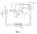
- Figure 1 is a block diagram showing a measurement apparatus according to one embodiment of the present invention.
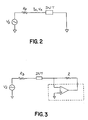
- Figure 2 is a diagram for explaining the principle of the present invention.
- Figure 3 is a diagram schematically showing one example of the measurement apparatus according to the prior art.
- Figure 2 is a diagram for explaining the principle of the present invention.
- I x V s /Z (1)
- V x (Z x /Z) * Vs (2)
- Z x stands for the impedance of the DUT
- Z for the overall impedance of the system
- V s for the AC voltage of the signal source
- R s for the internal resistance of the signal source
- I x and V x respectively for the current and voltage applied to the DUT.
- Z x and Z are functions of V s .
- Figure 1 is a schematic diagram showing an impedance measurement apparatus according to one embodiment of the present invention.
- the output of an AC signal source S is fed through a level control circuit 10 and a resistor R s to a device Z x to be measured (DUT).
- the other end of the DUT P is forced to be a virtual ground by the feedback circuit comprising a high gain amplifier 20 and a feedback resistor R.
- the vector ratio detector 30 includes a phase detector and a dual slope type ADC, it can be used to determine the digital values of V x and V R (represented in a vector form) with the operations well-known to those skilled in the art.
- the detector 30 is made to perform the digital conversion of the voltage V x in case the AC current of the DUT is to be controlled; the conversion of the voltage V R being required for controlling the AC voltage.
- Introducing the result of the digital conversion into the logic circuit 40 enables to calculate the new level control signal to the AC signal source, as was described above with reference to Figure 2.
- the logic circuit 40 acquires the digital data indicative of the AC voltage or current of the DUT, and computes and provides the AC signal source with a new level control signal value on the basis of the digital data for causing the AC voltage or current to approach a desired value.
- the repetitive calculation is quitted when this intermittent operation drives the AC voltage or current of the DUT within the range of allowable error relative to the desired value; then the required measurement is performed on the DUT.
- a multiplying-digital-to-analog converter can be used for the level control circuit 10.
- a warning indication may be asserted, when the logic circuit 40 detects the deviation out of the automatic adjust range.
- a single measurement provides the solution for a linear DUT (i.e., the DUT whose impedance is constant independent of the voltage or current thereof).
- the repetition is not guaranteed to always converge.
- some DUTs require another algorithm.
- F(a) * F(b) ⁇ 0 c will be employed as a for the next cycle; in case F(b) * F(c) , c will be the next b. This procedure will be repeated until F(c) falls within a predetermined error range.
- This preparatory measurement may be accomplished by, for example, sweeping the output of the AC signal source to observe the AC voltage (or current) of the DUT. Incidentally, this sweeping allows to find the range of the AC voltage (or current) that can be set for the DUT.
- the convergence can be guaranteed as well as made to be as quick as possible by selecting the appropriate algorithm for use based on the situation.
- the preparatory measurement is needed.
- selection between, for example, the bisection algorithm and the linear inverse interpolation may be done based on the convergence rate. That is, in case the convergence of the linear inverse interpolation is slow, the bisection algorithm is to be used; otherwise, the linear inverse interpolation is to be used.
- the condition of slowing down the convergence involves the solution x T which is unknown before starting the successive approximation.
- the following criterion may be used instead:
- the AC signal source can be controlled without any preparatory measurement, for example, as described below:
- f(x) may be assumed as monotonous in the interval [x min , x max ] for common DUTs.
- the bias voltage or current will converge to a target value in two or three cycles of the operations of the digital loop for the common DUT such as L, C, R and diode; although the cycle count can change depending upon various factors such as the mode of the nonlinearity of the particular DUT and the algorithm employed for determining the control signal for the next cycle on the basis of the voltage/current information of the DUT. Therefore, the present invention enjoys a high utility.
- the present invention enables the AC level of the voltage or current applied to the device under test to be kept constant, an improved repeatability of the measurement can be obtained even for the measurement of a device of nonlinearity.
- the intermittent feedback with the digital feedback loop for keeping the level constant prevents this feedback loop from interfering with the feedback loop for the measurement system itself, and thus does not degrade the analog stability of the measurement system.
Landscapes
- Physics & Mathematics (AREA)
- General Physics & Mathematics (AREA)
- Measurement Of Resistance Or Impedance (AREA)
- Investigating Or Analyzing Materials By The Use Of Electric Means (AREA)
Description
- The present invention relates to a measurement apparatus capable of measuring impedance or the like with high repeatability by keeping the measurement conditions as constant as possible.
- Common impedance measurement apparatus of the prior art, such as schematically shown in Figure 3, do not actively keep the AC level (of voltage or current) applied to the DUT (device under test) constant. In Figure 3, because of the requirement of maintaining the stability of the measurement system, the signal source resistance Rs cannot be reduced to excess, and thus it is usually determined at ten ohm or more. In the past, only an approximately constant voltage or current source was implemented by switching the signal source resistance Rs according to the impedance of the DUT. In such a method, it was practically difficult to set the signal level applied to the DUT at a level desired by the user of the measurement apparatus.
- US-A-4 481 464 discloses apparatus for measuring time-variant non-ideal device impedance utilising a current to voltage converter and an integrating vector voltage ratio measuring circuit.
- An object of the present invention is to overcome the problems of the prior art depicted in Fig. 3, and to keep the AC level applied to the DUT constant without degradation of the stability of the measurement system.
- In accordance with the present invention, a measurement apparatus for measuring an electrical characteristic of a device under test at a predetermined AC signal level, the device under test having first and second terminals, the measurement apparatus comprising:
signal source means with a controllable AC level for applying an AC signal to the first terminal of the device under test,
feedback circuit means, connected to the second terminal of the device under test, for forcing the second terminal of the device under test to be virtually grounded;
synchronous detector means, connected to the first terminal of said device under test and to the feedback circuit means, for obtaining measurement signals representing current and voltage of the device under test, and for performing synchronous detection of the measurement signals;
analog-digital converter means, connected to the synchronous detector means, for performing analog-digital conversion by integrating an output of the synchronous detector means; and
digital logic means, connected to the analog-digital converter means and responsive to an output of the analog-digital converter means, for intermittently controlling the AC level of the signal source means, the digital logic means using an approximation algorithm to control the AC level of the signal source means so as to cause the AC signal level applied to the device under test (DUT) to converge to said predetermined AC signal level. - Figure 1 is a block diagram showing a measurement apparatus according to one embodiment of the present invention.
- Figure 2 is a diagram for explaining the principle of the present invention.
- Figure 3 is a diagram schematically showing one example of the measurement apparatus according to the prior art.
- Figure 2 is a diagram for explaining the principle of the present invention. In this figure, the following two equations hold:


where Zx stands for the impedance of the DUT, Z for the overall impedance of the system, Vs for the AC voltage of the signal source, Rs for the internal resistance of the signal source, and Ix and Vx respectively for the current and voltage applied to the DUT. Because the impedance of the DUT is generally under the influence of the AC voltage Vs, Zx and Z are functions of Vs. Transforming the equation (1) by denoting Vs as x, Z as f(x), and the target value of the current through the DUT as ITGT results in the equation below:

Similarly, denoting Vs as x, Z/Zx as g(x), and the target of the voltage across the DUT as VTGT, we obtain the equation below:

Thus, in order to make Ix or Vx coincide with the target value, the signal source may be controlled so that the AC voltage of the signal source may be set to the solution of F(x) = 0 or G(x) = 0, respectively. Because the functions F(x) and G(x) determined by the impedance of the DUT are different from DUT to DUT, and often have nonlinearity, it is impractical to analytically obtain the solutions of the above-mentioned equations. Hence, an operation is taken to successively approximate the solutions. The successive approximation methods which can be used include the successive substitution, bisection algorithm and linear inverse interpolation, the detail of which will be described later. - Figure 1 is a schematic diagram showing an impedance measurement apparatus according to one embodiment of the present invention.
- In Figure 1, the output of an AC signal source S is fed through a
level control circuit 10 and a resistor Rs to a device Zx to be measured (DUT). The other end of the DUT P is forced to be a virtual ground by the feedback circuit comprising ahigh gain amplifier 20 and a feedback resistor R. The voltages Vx and VR respectively across the DUT and the range resistor (feedback resistor) R (VR = (the current flowing through the DUT) * (the resistance of the range resistor R)) are introduced into a vector ratio detector 30. (Because the point P is at the virtual ground, a substantially equal voltage is obtained by merely observing the potentials at the other ends of the DUT and the range resistor R, as shown in Figure 1.) Because the vector ratio detector 30 includes a phase detector and a dual slope type ADC, it can be used to determine the digital values of Vx and VR (represented in a vector form) with the operations well-known to those skilled in the art. Thus, with the control over the operations of the vector voltage ratio detector 30 by a microprocessor in thelogic circuit 40, the detector 30 is made to perform the digital conversion of the voltage Vx in case the AC current of the DUT is to be controlled; the conversion of the voltage VR being required for controlling the AC voltage. Introducing the result of the digital conversion into thelogic circuit 40 enables to calculate the new level control signal to the AC signal source, as was described above with reference to Figure 2. - In this way, the
logic circuit 40 acquires the digital data indicative of the AC voltage or current of the DUT, and computes and provides the AC signal source with a new level control signal value on the basis of the digital data for causing the AC voltage or current to approach a desired value. The repetitive calculation is quitted when this intermittent operation drives the AC voltage or current of the DUT within the range of allowable error relative to the desired value; then the required measurement is performed on the DUT. - In the embodiment, a multiplying-digital-to-analog converter can be used for the
level control circuit 10. In addition, a warning indication may be asserted, when thelogic circuit 40 detects the deviation out of the automatic adjust range. - The examples of the algorithms for determining the new control signal for the next cycle on the basis of the information about the AC voltage/current applied to the DUT will follow (Though the examples are shown in connection with the current, these algorithms apply to the case of the voltage).
- The equation

gives the following:

Then, starting from an appropriate first approximation x₁, repeat the following computation:

Though not always converging, if it converges, the limit will be the solution. Let the true value of the solution be xT and the error of the k-th approximation xk - xT be ek. Then it is sufficient for the convergence that for any sufficiently large number k there exists a constant C whose absolute value is less than 1 such that the constant C satisfies the following condition:

Because this condition can be transformed to:

it is sufficient that the following condition holds over the neighborhood of xT, after all:

This algorithm need not any preparatory measurement for selecting a first approximation, as is opposed to the bisection algorithm described below. In addition, a single measurement provides the solution for a linear DUT (i.e., the DUT whose impedance is constant independent of the voltage or current thereof). For a nonlinear DUT, however, the repetition is not guaranteed to always converge. Thus, some DUTs require another algorithm. - Before starting the successive approximation, a preparatory measurement is conducted to locate two points, a and b, such that the following condition is satisfied:

and F(c) is determined for


- In the bisection algorithm, it is guaranteed that a convergence never fails to occur in a certain number of repetitions. On the other hand, however, it is necessary to perform a preparatory measurement for determining the first approximation for a and b. This preparatory measurement may be accomplished by, for example, sweeping the output of the AC signal source to observe the AC voltage (or current) of the DUT. Incidentally, this sweeping allows to find the range of the AC voltage (or current) that can be set for the DUT.
- As in the bisection algorithm, provide an interval [a, b] satisfying the condition:

and perform the following procedure: - (i) approximate F(x) by a straight line passing through two points, (a, F(a)) and (b, F(b)). Let the intersection of this straight line and the x-axis be c, and obtain F(c). c is represented as below:

- (ii) If


Repeat these steps, (i) and (ii), until F(c) falls within a predetermined error range. - The feature of this algorithm is substantially similar to that of the bisection algorithm, but the convergence is quicker if the DUT is approximately linear (if the DUT is completely linear, it converges in a single cycle). Depending upon the mode of the nonlinearity, however, the convergence can extremely slow. In this case, the following condition holds:

(or, the condition with the inequality symbol reversed) where xT represents the solution. - On controlling the AC signal source with the aforementioned algorithms, the convergence can be guaranteed as well as made to be as quick as possible by selecting the appropriate algorithm for use based on the situation.
- In case the user is not sure what level of the AC voltage (or current) can be set, the preparatory measurement is needed. In such a preparatory measurement, selection between, for example, the bisection algorithm and the linear inverse interpolation may be done based on the convergence rate. That is, in case the convergence of the linear inverse interpolation is slow, the bisection algorithm is to be used; otherwise, the linear inverse interpolation is to be used. The condition of slowing down the convergence involves the solution xT which is unknown before starting the successive approximation. Thus, the following criterion may be used instead:
- Use the bisection algorithm, if


In such a case that the user can predict the range of the AC voltage (or current) to be set for the DUT, the AC signal source can be controlled without any preparatory measurement, for example, as described below: - Though the solution is basically determined on the basis of the successive substitution, because of the possibility of divergence, the following four possible cases are considered, with the minimum and maximum of the AC voltage that can be set denoted as xmin and xmax respectively:


The successive substitution diverges for the cases (i) and (iii). In this discussion, f(x) may be assumed as monotonous in the interval [xmin, xmax] for common DUTs. Thus, for the n-th approximated solution xn, the following condition holds:
for the cases (i) and (ii) (i.e.,


and
for the cases (iii) and (iv) (i.e.,

Then, at first apply the successive substitution with the first approximated solution determined as


(Because f(x) is monotonous, either one of the above conditions holds.) Thus, the convergence is guaranteed for any monotonous f(x). - With the configuration and operation as above, the bias voltage or current will converge to a target value in two or three cycles of the operations of the digital loop for the common DUT such as L, C, R and diode; although the cycle count can change depending upon various factors such as the mode of the nonlinearity of the particular DUT and the algorithm employed for determining the control signal for the next cycle on the basis of the voltage/current information of the DUT. Therefore, the present invention enjoys a high utility.
- As is described in detail heretofore, because the present invention enables the AC level of the voltage or current applied to the device under test to be kept constant, an improved repeatability of the measurement can be obtained even for the measurement of a device of nonlinearity. In addition, the intermittent feedback with the digital feedback loop for keeping the level constant prevents this feedback loop from interfering with the feedback loop for the measurement system itself, and thus does not degrade the analog stability of the measurement system.
Claims (4)
- A measurement apparatus for measuring an electrical characteristic of a device under test at a predetermined AC signal level, the device under test having first and second terminals, the measurement apparatus comprising:
signal source means (10) with a controllable AC level for applying an AC signal to the first terminal of the device under test (DUT),
feedback circuit means (20, R), connected to the second terminal (P) of the device under test (DUT), for forcing the second terminal (P) of the device under test (DUT) to be virtually grounded;
synchronous detector means (30), connected to the first terminal of said device under test (DUT) and to the feedback circuit means (20, R), for obtaining measurement signals representing current and voltage of the device under test (DUT), and for performing synchronous detection of the measurement signals;
analog-digital converter means (30), connected to the synchronous detector means (30), for performing analog-digital conversion by integrating an output of the synchronous detector means (30); and
digital logic means (40), connected to the analog-digital converter means (30) and responsive to an output of the analog-digital converter means (30), for intermittently controlling the AC level of the signal source means (10), the digital logic means (40) using an approximation algorithm to control the AC level of the signal source means (10) so as to cause the AC signal level applied to the device under test (DUT) to converge to said predetermined AC signal level. - The measurement apparatus of Claim 1, wherein the approximation algorithm is selected from a set consisting of successive substitution, bisection and linear interpolation algorithms.
- The measurement apparatus of Claim 1, wherein the predetermined AC signal level is a predetermined current flowing through the device under test (DUT).
- The measurement apparatus of Claim 1, wherein the predetermined AC signal level is a predetermined voltage across the device under test (DUT).
Applications Claiming Priority (2)
| Application Number | Priority Date | Filing Date | Title |
|---|---|---|---|
| JP20955/88 | 1988-01-29 | ||
| JP63020955A JP2720970B2 (en) | 1988-01-29 | 1988-01-29 | Measuring instrument |
Publications (2)
| Publication Number | Publication Date |
|---|---|
| EP0327254A1 EP0327254A1 (en) | 1989-08-09 |
| EP0327254B1 true EP0327254B1 (en) | 1993-08-18 |
Family
ID=12041607
Family Applications (1)
| Application Number | Title | Priority Date | Filing Date |
|---|---|---|---|
| EP89300738A Expired - Lifetime EP0327254B1 (en) | 1988-01-29 | 1989-01-26 | Measurement apparatus |
Country Status (4)
| Country | Link |
|---|---|
| US (1) | US5019781A (en) |
| EP (1) | EP0327254B1 (en) |
| JP (1) | JP2720970B2 (en) |
| DE (1) | DE68908430T2 (en) |
Families Citing this family (11)
| Publication number | Priority date | Publication date | Assignee | Title |
|---|---|---|---|---|
| KR0175839B1 (en) * | 1992-08-04 | 1999-05-15 | 윤종용 | Device for calculating passive element value by current vector |
| US5734373A (en) * | 1993-07-16 | 1998-03-31 | Immersion Human Interface Corporation | Method and apparatus for controlling force feedback interface systems utilizing a host computer |
| JP3809223B2 (en) * | 1996-05-30 | 2006-08-16 | アジレント・テクノロジーズ・インク | Impedance measuring device |
| JP2001201524A (en) * | 2000-01-20 | 2001-07-27 | Agilent Technologies Japan Ltd | Ratio measuring device of electric signal, electric element measuring device, calibration method of electric element measuring device and ratio measuring method of electric signal |
| JP2004317391A (en) * | 2003-04-18 | 2004-11-11 | Agilent Technol Inc | Current-voltage converter and impedance measuring device |
| US7352312B2 (en) * | 2005-11-07 | 2008-04-01 | Washburn Robert D | Variable passive components with high resolution value selection and control |
| JP4735250B2 (en) * | 2005-12-28 | 2011-07-27 | 横河電機株式会社 | Measuring device |
| JP2010038699A (en) * | 2008-08-04 | 2010-02-18 | Hitachi Kokusai Denki Engineering:Kk | Measurement current value determining method and four-probe resistivity measuring apparatus |
| US8217667B2 (en) * | 2009-01-16 | 2012-07-10 | Hill-Rom Services, Inc. | Method and apparatus for piezoelectric sensor status assessment |
| US8547120B1 (en) * | 2009-05-13 | 2013-10-01 | Keithley Instruments, Inc. | High speed AC current source |
| LU93211B1 (en) * | 2016-09-14 | 2018-04-05 | Iee Sa | Method for determining a sense impedance in a guard-sense capacitive sensor |
Family Cites Families (9)
| Publication number | Priority date | Publication date | Assignee | Title |
|---|---|---|---|---|
| US3325727A (en) * | 1964-11-05 | 1967-06-13 | Honeywell Inc | Capacity measuring device including an integrating analog to digital converter |
| US4080562A (en) * | 1976-03-25 | 1978-03-21 | Gull Airborne Instruments, Inc. | Apparatus for measuring capacitance or resistance and for testing a capacitance responsive gaging system |
| DE2838257A1 (en) * | 1978-09-01 | 1980-03-13 | Udo Dr Ing Unrau | HF measuring device with level control by reference signal - has synchronised distributors directing signal through test and reference paths |
| JPS56126769A (en) * | 1980-03-11 | 1981-10-05 | Yokogawa Hewlett Packard Ltd | Impedance meter |
| US4315219A (en) * | 1980-04-07 | 1982-02-09 | Canadian Patents & Development Limited | Amplitude controlled digital oscillator |
| US4458196A (en) * | 1981-08-05 | 1984-07-03 | John Fluke Mfg. Co., Inc. | Method and apparatus for high speed resistance, inductance and capacitance measurement |
| JPS5875074A (en) * | 1981-10-30 | 1983-05-06 | Yokogawa Hewlett Packard Ltd | Measuring device for capacity or other parameter |
| JPS6071966A (en) * | 1983-09-28 | 1985-04-23 | Advantest Corp | Digital spectrum analyzer |
| GB8604125D0 (en) * | 1986-02-19 | 1986-03-26 | Rowlands S L | Resistance element simulator |
-
1988
- 1988-01-29 JP JP63020955A patent/JP2720970B2/en not_active Expired - Fee Related
-
1989
- 1989-01-26 DE DE89300738T patent/DE68908430T2/en not_active Expired - Fee Related
- 1989-01-26 EP EP89300738A patent/EP0327254B1/en not_active Expired - Lifetime
-
1990
- 1990-10-25 US US07/604,382 patent/US5019781A/en not_active Expired - Lifetime
Also Published As
| Publication number | Publication date |
|---|---|
| JP2720970B2 (en) | 1998-03-04 |
| JPH01195371A (en) | 1989-08-07 |
| US5019781A (en) | 1991-05-28 |
| EP0327254A1 (en) | 1989-08-09 |
| DE68908430D1 (en) | 1993-09-23 |
| DE68908430T2 (en) | 1994-04-21 |
Similar Documents
| Publication | Publication Date | Title |
|---|---|---|
| US4947469A (en) | Resistive fault location method and device for use on electrical cables | |
| US5585954A (en) | Apparatus for measuring optical transmission characteristic | |
| US5019781A (en) | Source level control for impedance meter | |
| US4544879A (en) | Stimulus/measuring unit for DC characteristics measuring | |
| US3842247A (en) | Apparatus and method for measuring envelope delay utilizing {90 -point technique | |
| US4282576A (en) | Indicator diagram based AC electric energy meter | |
| US5448173A (en) | Triple-probe plasma measuring apparatus for correcting space potential errors | |
| EP0693692A2 (en) | Voltage and resistance synthesizer using pulse width modulation | |
| US4814689A (en) | Method of measuring a cable delay time | |
| US4546441A (en) | Method and apparatus for time based measurement of impedance | |
| EP0104998A2 (en) | Quasi-asynchronous sampling method and system | |
| EP1684081A1 (en) | Method and device for characterizing the linear properties of an electrical component | |
| US4717883A (en) | Method and apparatus for reducing errors in a sampling system utilizing an error-sampled feedback loop | |
| RU2142142C1 (en) | Device locating point of fault in power transmission and communication lines | |
| US4249127A (en) | Standing wave ratio measuring system | |
| JPH0718901B2 (en) | Apparatus and method for determining values of circuit elements in three-terminal equivalent circuit | |
| EP0076120B1 (en) | Current generating circuit device for measuring cryogenic liquefied gas liquid level meter with superconductive wire | |
| Podobedov et al. | New apparatus for precise synchronous phase shift measurements in storage rings | |
| CN120908512B (en) | Quantum current measuring method and measuring device based on quantum abnormal Hall effect | |
| US4011502A (en) | Logarithmic ratemeter with bistable signal comparison | |
| US3449666A (en) | Impedance sensing circuit having amplifier means for maintaining a pair of points at the same potential | |
| JPH0989954A (en) | Electronic part and electronic circuit network measuring device | |
| Huning et al. | System identification for the digital RF control system at the TESLA Test Facility | |
| SU1134917A1 (en) | Device for measuring uhf power | |
| SU1615630A1 (en) | Method of measuring instantaneous values of electric signal |
Legal Events
| Date | Code | Title | Description |
|---|---|---|---|
| PUAI | Public reference made under article 153(3) epc to a published international application that has entered the european phase |
Free format text: ORIGINAL CODE: 0009012 |
|
| AK | Designated contracting states |
Kind code of ref document: A1 Designated state(s): DE FR GB |
|
| 17P | Request for examination filed |
Effective date: 19900115 |
|
| 17Q | First examination report despatched |
Effective date: 19920218 |
|
| GRAA | (expected) grant |
Free format text: ORIGINAL CODE: 0009210 |
|
| AK | Designated contracting states |
Kind code of ref document: B1 Designated state(s): DE FR GB |
|
| REF | Corresponds to: |
Ref document number: 68908430 Country of ref document: DE Date of ref document: 19930923 |
|
| ET | Fr: translation filed | ||
| PLBE | No opposition filed within time limit |
Free format text: ORIGINAL CODE: 0009261 |
|
| STAA | Information on the status of an ep patent application or granted ep patent |
Free format text: STATUS: NO OPPOSITION FILED WITHIN TIME LIMIT |
|
| 26N | No opposition filed | ||
| REG | Reference to a national code |
Ref country code: FR Ref legal event code: TP |
|
| REG | Reference to a national code |
Ref country code: GB Ref legal event code: 732E |
|
| REG | Reference to a national code |
Ref country code: GB Ref legal event code: IF02 |
|
| PGFP | Annual fee paid to national office [announced via postgrant information from national office to epo] |
Ref country code: FR Payment date: 20060117 Year of fee payment: 18 |
|
| PGFP | Annual fee paid to national office [announced via postgrant information from national office to epo] |
Ref country code: GB Payment date: 20060119 Year of fee payment: 18 |
|
| PGFP | Annual fee paid to national office [announced via postgrant information from national office to epo] |
Ref country code: DE Payment date: 20060228 Year of fee payment: 18 |
|
| PG25 | Lapsed in a contracting state [announced via postgrant information from national office to epo] |
Ref country code: DE Free format text: LAPSE BECAUSE OF NON-PAYMENT OF DUE FEES Effective date: 20070801 |
|
| GBPC | Gb: european patent ceased through non-payment of renewal fee |
Effective date: 20070126 |
|
| REG | Reference to a national code |
Ref country code: FR Ref legal event code: ST Effective date: 20070930 |
|
| PG25 | Lapsed in a contracting state [announced via postgrant information from national office to epo] |
Ref country code: GB Free format text: LAPSE BECAUSE OF NON-PAYMENT OF DUE FEES Effective date: 20070126 |
|
| PG25 | Lapsed in a contracting state [announced via postgrant information from national office to epo] |
Ref country code: FR Free format text: LAPSE BECAUSE OF NON-PAYMENT OF DUE FEES Effective date: 20070131 |