EP0326492B1 - Device and method for carrying out operations and/or interventions in a well - Google Patents
Device and method for carrying out operations and/or interventions in a well Download PDFInfo
- Publication number
- EP0326492B1 EP0326492B1 EP89400227A EP89400227A EP0326492B1 EP 0326492 B1 EP0326492 B1 EP 0326492B1 EP 89400227 A EP89400227 A EP 89400227A EP 89400227 A EP89400227 A EP 89400227A EP 0326492 B1 EP0326492 B1 EP 0326492B1
- Authority
- EP
- European Patent Office
- Prior art keywords
- tubing
- well
- connecting element
- accordance
- zones
- Prior art date
- Legal status (The legal status is an assumption and is not a legal conclusion. Google has not performed a legal analysis and makes no representation as to the accuracy of the status listed.)
- Expired - Lifetime
Links
- 238000000034 method Methods 0.000 title claims description 15
- 239000012530 fluid Substances 0.000 claims description 48
- 238000004519 manufacturing process Methods 0.000 claims description 36
- 230000015572 biosynthetic process Effects 0.000 claims description 14
- 238000005755 formation reaction Methods 0.000 claims description 14
- 230000005540 biological transmission Effects 0.000 claims description 13
- 238000004891 communication Methods 0.000 claims description 11
- 238000005259 measurement Methods 0.000 claims description 8
- 239000007788 liquid Substances 0.000 claims description 7
- 238000007789 sealing Methods 0.000 claims description 7
- 239000000126 substance Substances 0.000 claims description 7
- 230000000295 complement effect Effects 0.000 description 2
- 210000000056 organ Anatomy 0.000 description 2
- 238000005086 pumping Methods 0.000 description 2
- 230000001174 ascending effect Effects 0.000 description 1
- 238000009529 body temperature measurement Methods 0.000 description 1
- 239000004020 conductor Substances 0.000 description 1
- 238000013016 damping Methods 0.000 description 1
- 230000003247 decreasing effect Effects 0.000 description 1
- 238000006073 displacement reaction Methods 0.000 description 1
- 238000005553 drilling Methods 0.000 description 1
- 230000000694 effects Effects 0.000 description 1
- 230000008030 elimination Effects 0.000 description 1
- 238000003379 elimination reaction Methods 0.000 description 1
- 210000004907 gland Anatomy 0.000 description 1
- 230000005484 gravity Effects 0.000 description 1
- 229930195733 hydrocarbon Natural products 0.000 description 1
- 150000002430 hydrocarbons Chemical class 0.000 description 1
- 230000002093 peripheral effect Effects 0.000 description 1
- 230000000630 rising effect Effects 0.000 description 1
- 239000013049 sediment Substances 0.000 description 1
- 239000010802 sludge Substances 0.000 description 1
- XLYOFNOQVPJJNP-UHFFFAOYSA-N water Substances O XLYOFNOQVPJJNP-UHFFFAOYSA-N 0.000 description 1
Images

Classifications
-
- E—FIXED CONSTRUCTIONS
- E21—EARTH DRILLING; MINING
- E21B—EARTH DRILLING, e.g. DEEP DRILLING; OBTAINING OIL, GAS, WATER, SOLUBLE OR MELTABLE MATERIALS OR A SLURRY OF MINERALS FROM WELLS
- E21B43/00—Methods or apparatus for obtaining oil, gas, water, soluble or meltable materials or a slurry of minerals from wells
- E21B43/14—Obtaining from a multiple-zone well
-
- E—FIXED CONSTRUCTIONS
- E21—EARTH DRILLING; MINING
- E21B—EARTH DRILLING, e.g. DEEP DRILLING; OBTAINING OIL, GAS, WATER, SOLUBLE OR MELTABLE MATERIALS OR A SLURRY OF MINERALS FROM WELLS
- E21B23/00—Apparatus for displacing, setting, locking, releasing, or removing tools, packers or the like in the boreholes or wells
- E21B23/08—Introducing or running tools by fluid pressure, e.g. through-the-flow-line tool systems
-
- E—FIXED CONSTRUCTIONS
- E21—EARTH DRILLING; MINING
- E21B—EARTH DRILLING, e.g. DEEP DRILLING; OBTAINING OIL, GAS, WATER, SOLUBLE OR MELTABLE MATERIALS OR A SLURRY OF MINERALS FROM WELLS
- E21B23/00—Apparatus for displacing, setting, locking, releasing, or removing tools, packers or the like in the boreholes or wells
- E21B23/14—Apparatus for displacing, setting, locking, releasing, or removing tools, packers or the like in the boreholes or wells for displacing a cable or cable-operated tool, e.g. for logging or perforating operations in deviated wells
-
- E—FIXED CONSTRUCTIONS
- E21—EARTH DRILLING; MINING
- E21B—EARTH DRILLING, e.g. DEEP DRILLING; OBTAINING OIL, GAS, WATER, SOLUBLE OR MELTABLE MATERIALS OR A SLURRY OF MINERALS FROM WELLS
- E21B47/00—Survey of boreholes or wells
- E21B47/06—Measuring temperature or pressure
-
- E—FIXED CONSTRUCTIONS
- E21—EARTH DRILLING; MINING
- E21B—EARTH DRILLING, e.g. DEEP DRILLING; OBTAINING OIL, GAS, WATER, SOLUBLE OR MELTABLE MATERIALS OR A SLURRY OF MINERALS FROM WELLS
- E21B47/00—Survey of boreholes or wells
- E21B47/10—Locating fluid leaks, intrusions or movements
Definitions
- the present invention relates to a method and a device for carrying out operations and / or interventions in a well drilled in geological oil or gas formations, in particular a horizontal well.
- the invention is particularly adapted to the evolutionary exploitation of geological formations, and allows measurements of flow, temperature, pressure, etc. which can be carried out on the effluents of each of the formations in production.
- the invention is particularly advantageous because of the speed of implementation of the device and of the method according to the invention, since it does not exclude certain types of work, such as those using the technique working with the cable called "wire line", which one might have to do during production.
- the invention also makes it possible to control tools placed at the bottom of a well, these tools being able for example to be valves controlling the selective production of geological formation.
- Orders for tools or measurements with the method or device according to the invention are particularly advantageous because of the speed of their implementation (from inside the casing) and the full possibilities of maneuvering the casing (rotation , advance, dismantling %) which is not hampered by fixed or peripheral lines as commonly used.
- the invention advantageously applies to the production of horizontal wells. Indeed, particularly in oil drilling, the production of a well causes a displacement of the various layers of liquids in the production area, called the cone effect (in English "coning"). In production in horizontal wells, the arrival of undesirable liquids, such as water, is generally carried out irregularly along the well, so much so that a large part of the desired liquid, such as oil, n is not extracted from training.
- the invention provides a method for carrying out operations and / or interventions, such as measurements, in a well having a casing with a diameter smaller than that of the well, the well being drilled in geological formations and comprising at least two distinct fluid production zones, said zones being in communication with said well.
- the tools and / or instruments may be integral with the casing.
- At least one of the instruments could be adapted to measure the physical and / or chemical and / or physico-chemical characteristics of the fluids present in a production area. At least one of the tools can be adapted to modify fluids in the production area.
- the first connection member may be placed at the lower end of the casing.
- the fluids produced selectively by these production zones can be transferred through the interior of the casing.
- a conduit adapted to communicate with the lower end of the casing can be placed in the well by a hydraulic connection and / or a channel, this connection and this channel being located in the vicinity of the first connection member.
- the invention further provides a device for performing operations and / or interventions, such as measurements, in a well with casing.
- the casing is of a diameter smaller than that of the well, this well being drilled in geological formations and comprising at least two distinct zones for the production of a fluid, said zones being in communication with the well and being isolated between them by sealing means.
- the device further comprises in its interior a first connection member usable in a liquid medium, the first member being connected by lines to at least one instrument and / or tool arranged in each of the production zones, said instrument and / or tool being suitable for carrying out said operations and / or interventions in connection with said fluid, the first connection member being adapted to cooperate with a second connection member connected by a transmission cable to the ground surface, the casing being adapted to allow descent of the second organ from the surface and its connection with the first organ.
- the tools and / or instruments may be integral with the casing.
- the tubing may include means for selectively placing these areas in communication with the interior of the tubing.
- the first connection member may be disposed at the lower end of the casing.
- the device may include a conduit communicating with the casing substantially at the level of the first connection member and opening onto the ground surface.
- the well comprising a part which is strongly inclined towards the vertical, even horizontal, and equipped with a device according to the invention, is operated from the surface of the ground.
- This well 1 comprises over a certain length a casing 2 inside which is a casing 3 and a conduit 4, which crosses geological formations for which it is desired to produce fluids.
- Each of the production zones 30, 31, 32 communicates with zones internal to the casing 2 by orifices 13, 15, 17 respectively. This area can be communicated at will with the interior of the first casing 3 by circulation valves, such as valves with sliding sleeves 14, 16, 18 respectively.
- valves 14, 16, 18 are normally fitted with non-return valves preventing the circulation of fluid from the casing to the formations, but we can very well remove these valves, when, for example, we want to proceed with the fracturing of an area.
- the lower end of the conduit 4 comprises a valve 11 which can be controlled remotely, such as a sliding jacket valve similar to the valves 14, 16, 18 and making it possible to put the lower part 33 of the well 1 in communication with the casing 3 and the conduit 4, either to produce the fluids from the bottom of the well (via the conduit 4), or for the needs of normal operation of the well.
- a valve 11 which can be controlled remotely, such as a sliding jacket valve similar to the valves 14, 16, 18 and making it possible to put the lower part 33 of the well 1 in communication with the casing 3 and the conduit 4, either to produce the fluids from the bottom of the well (via the conduit 4), or for the needs of normal operation of the well.
- the conduit 4 connected to the casing 3 by the hydraulic connection element 12 comprises, if necessary, arranged at the required depth, a circulation pump 19 which sucks the fluid from the formations and discharges it to the ground surface through the mouth 20
- the pump 19 can be a hydraulic, electric or mechanical pump, such as the plunger of a rod and balance pump.
- the position of the pump 19 in the well may be located substantially below the dynamic level of training in production. According to the invention, the direction of circulation of the pump fluid can be unique and ascending.
- the inner and lower end of the casing 3 comprises a first connection member 10 connected by electrical lines 40 to instruments and / or tools 34, 35, 36, 37 arranged in each of the production zones 30, 31, 32, 33 .
- This first connection member 10 is adapted to cooperate with a second connection member 21 connected to the ground surface by a transmission cable 22.
- This second connection member 21 is introduced into the casing 3 at its upper part, then is moved to the second connection member 10 to establish the cooperation of the latter.
- the second connection member 21 may include a load bar 21a which allows the descent by gravity of this second member 21, in particular for vertical wells or slightly deviated from the vertical.
- This member 21 may also include linings adapted to cooperate with the inside of casing 3, in particular for wells that are strongly deviated from the vertical or even horizontal, or even rising, in order to provide a seal and thus move this member 21 by hydraulic pumping of the product. , either by the station 29 which is connected to the casing 3 by a pipe 28, or by the circulation pump 19 located in the duct 4.
- the end of the casing comprises a channel 12a, located below the hydraulic connection 12 and which allows a circulation of fluid, this hydraulic connection being adapted to allow the evacuation of sludge or other sediments and also being adapted to allow the elimination of the fluid present between the first 10 and second 21 members, in particular during their connection, and thanks to a suitable section.
- the hydraulic link 12 is also adapted to allow the damping of the inertia of the second member 21 during its connection with the first member 10.
- the upper end of the casing 3 comprises a cable gland 23 through which the transmission cable 22 passes before being returned by two pulleys 24, 25 to the winch 26 controlled by the station 27.
- well 1 When producing a well 1, such as that drilled in geological formations comprising hydrocarbons, well 1 is equipped with at least one casing 3 and a conduit 4 for safety reasons, so as to avoid a circulation of fluid between the casing 2 and the casing 3.
- the second connecting member 21 when the second connecting member 21 is moved, the fluid present under it rises through the conduit 4.
- the second connecting member 10 is connected to the measuring instruments 34, 35, 36, 37 respectively, arranged in the completion zones 30, 31, 32, 33, by means of the electrical lines 38, 39, 40, 41.
- These instruments 34, 35, 36, 37 are adapted to measure the flow of fluid passing through the valves 14, 16, 18, 11 respectively, the temperature and the pressure of the fluids in each of the completion zones 30, 31, 32, 33 respectively. It is possible, in the same way as one performs the pressure, flow and temperature measurements, to carry out all other kinds of physical and / or chemical and / or physico-chemical measurements, such as the resistivity of the fluids of the zones of production.
- the valves 14, 16, 18 are selectively controlled from the ground surface, either by key tools (21, 21a), or by hydraulic control. These key tools are operated with the cable for vertical or slightly deflected wells, or with hydraulic motors for wells admitting hydraulic circulation, as is practiced with the so-called T.F.L. (from the English "Through Flow Line"), or any other means, such as that of French patent application EN - 87/11 749.
- FIG. 2 shows in detail a hydraulic valve 45 with a sliding jacket 46, 47 adapted to the selective production of a well according to the invention.
- This valve 45 allows the exterior and interior of the casing to be placed in communication or not.
- a hydraulic line 49 ensuring the energy source of the power elements, such as elements similar to the valve 45, communicates by a connection 50 with the valve 45.
- distribution means such as a solenoid valve 51 , connected by an electric cable 48 to the socket 10 placed at the lower end of the casing 3 ( Figure 1).
- This solenoid valve 45 opens and closes the communication between the hydraulic line 45 and the hydraulic thrust chamber 52 of the hydraulic sliding jacket 46.
- the valve 45 comprises a cylindrical outer body 53 interposed in the casing 3 thanks to a female conical connector 54 and a male conical connector 55 respectively arranged at the top and at the bottom of the valve.
- this body 53 producing the outer casing of the valve are arranged, substantially in the same plane perpendicular to the axis of the casing, four closable orifices 56 modifying the communication between the interior and the exterior of the casing.
- the orifices 56 are closed by sliding the hydraulic jacket 46 or the safety jacket 47.
- An extension 57 separating the liners 46 and 47, defines with the hydraulic liner 46 and the body 53 the hydraulic thrust chamber 52, and ensures the guiding of the liners 46 and 47.
- the hydraulic jacket 46 slides between two extreme positions defined on the one hand by the cooperation of an opening stop 58 with the upper end 59 of the hydraulic jacket 46, and on the other hand by the cooperation of a heel 60 a groove 61 formed in the lower part of the hydraulic jacket 46 with the heel 62 of the key 63.
- the key 63 is integral with the extension 57 and by cooperating with the groove 61 rotates the hydraulic jacket 46 relative to to the body 53 of the valve.
- a return spring 64 cooperating with the lower end piece 65 of the hydraulic jacket 46 and a shoulder 66 of the extension 57, ensures the return to the rest position of the hydraulic jacket 46 when the pressure inside the chamber thrust 52 becomes less than a predetermined value.
- this space 67 can be connected with a compensation chamber filled with a fluid that remains clean, such as oil.
- the safety jacket 47 is controlled by a key seat 74 adapted to cooperate with the bolt of a tool circulating in the casing.
- the upper part 75 of the valve body 53 comprises, at the level of the safety jacket 47, a chamfer 76 adapted to release the bolt.
- the jacket 47 is positioned in rotation relative to the body 53 by means of a lug 77 integral with the extension 57 and cooperating with a groove 78 formed in the jacket 47.
- the lower end of the valve 45 comprises a nozzle 79 fixed to the body 53 by a thread 80, the nozzle being provided with the male conical connector 55.
- valve 45 is shown "normally open", that is to say that when the pressure of the fluid acting on the hydraulic jacket 46 is less than a determined value, the orifices arranged in the valve body do not are not obstructed by the jacket 46 due to the return force of the spring 64 which makes the opening stop 58 cooperate with the upper end 59 of the hydraulic jacket 46.
- the thrust chamber 52 corresponds to a reservoir adapted to contain a variable mass of hydraulic fluid.
- the orifices of the valve 45 are closed by controlling, by the electric line 48, the opening of the distribution means 51, by putting a suitable pressure in the line 49, so as to create a flow of fluid in a first direction and thus lower the shirt 46.
- the orifices of the valves 45 are opened by opening the distribution means 51, so as to put the thrust chamber 52 into communication with the hydraulic line and by putting a suitable pressure in the line 49, so as to create a flow of fluid in a second direction opposite to the first direction and thus raise the jacket 46, this pressure being less than the pressure for closing the orifices.
- FIG. 3 schematically shows a device comprising hydraulic tools and / or instruments 81, 82, 83 arranged on a casing 90 placed in the well 1, the device being in particular suitable for the selective production of different zones, such as zones 30, 31 , 32, 33 in Figure 1 or 84, 85, 86 in Figure 3.
- These tools and / or instruments may be, for example valves illustrated in Figure 2.
- the areas 84, 85, 86 are respectively delimited by sealing elements 87-88, 88-89, 89 and the bottom of the well.
- the device comprises a first line 91 and possibly a second hydraulic line 92, these lines being connected to the tools and / or instruments by connections 93, 94 respectively.
- connections 93 of the first hydraulic line 91 are arranged distribution means.
- Means for distributing the connections 93 are controlled by an electric line 95 connected to a first electrical connection member 96 disposed at the lower and inner part of the casing and adapted to cooperate with a second complementary electrical connection member connected to the surface of the ground by a transmission cable 22 ( Figure 1).
- these means can be controlled by hydraulic control lines connected, for example, to a hydraulic control connection member.
- the first line 91 and possibly the second hydraulic line 92 are connected to a hydraulic energy generator disposed either on the surface of the ground or in the vicinity of the tools and / or instruments.
- the transmission cable may include an electric power line making it possible to supply a hydraulic energy generator placed in the vicinity of the tools and / or instruments.
- the first line 91 and possibly the second hydraulic line 92 may be connected to a hydraulic connection member disposed inside the casing at its lower part, in the same way as the electric line 95 is connected to the electric connection member , this hydraulic connection member cooperating with a complementary member connected to the surface of the ground by a hydraulic pipe.
- hydraulic and electrical connection members may be associated in the same connection member, and likewise these hydraulic and electrical lines may be associated in the same line.
- At least two tools and / or instruments 81, 82, 83 using only a hydraulic line tools and / or instruments provided with means of reminder to return to an initial position when the pressure has decreased and distribution means are used arranged on connections 93 of the first hydraulic line 91 with the tools and / or instruments.
- the distribution means of the first tool and / or instrument are closed.
- the distribution means of the first tool and / or instrument are opened, the pressure in the first hydraulic line is released.
- a first hydraulic line 91 is used comprising connections 93 with the tools and / or instruments, the circulation in these connections being controlled by distribution means placed on each of these connections, and a second hydraulic line 92 comprising connections with the tools and / or instruments.
- a positive or negative pressure difference is made between the first and the second lines.
Description
La présente invention concerne une méthode et un dispositif pour effectuer des opérations et/ou des interventions dans un puits foré dans des formations géologiques pétrolières ou gazières, notamment un puits horizontal.The present invention relates to a method and a device for carrying out operations and / or interventions in a well drilled in geological oil or gas formations, in particular a horizontal well.
L'invention est notamment adaptée à l'exploitation évolutive de formation géologiques, et permet les mesures de débit, de température, de pression etc... que l'on peut effecteur sur les effluents de chacune des formations en production.The invention is particularly adapted to the evolutionary exploitation of geological formations, and allows measurements of flow, temperature, pressure, etc. which can be carried out on the effluents of each of the formations in production.
Pour ce type d'usage, l'invention est particulièrement avantageuse du fait de la rapidité de mise en oeuvre du dispositif et de la méthode selon l'invention, car elle n'exclu pas certains types de travaux, tels que ceux utilisant la technique de travail au câble dite de "wire line", que l'on pourrait être amenés à faire pendant la production.For this type of use, the invention is particularly advantageous because of the speed of implementation of the device and of the method according to the invention, since it does not exclude certain types of work, such as those using the technique working with the cable called "wire line", which one might have to do during production.
L'invention permet aussi de commander des outils disposés au fond d'un puits, ces outils pouvant par exemple être des vannes commandant la production sélective de formation géologique.The invention also makes it possible to control tools placed at the bottom of a well, these tools being able for example to be valves controlling the selective production of geological formation.
Les commandes d'outils ou des mesures avec la méthode ou le dispositif selon l'invention, sont particulièrement avantageuses du fait de la rapidité de leur mise en oeuvre (par l'intérieur du tubage) et des pleines possibilités de manoeuvre du tubage (rotation, avance, démontage...) qui n'est pas gênée par des lignes fixes ou périphériques telles que couramment utilisées.Orders for tools or measurements with the method or device according to the invention are particularly advantageous because of the speed of their implementation (from inside the casing) and the full possibilities of maneuvering the casing (rotation , advance, dismantling ...) which is not hampered by fixed or peripheral lines as commonly used.
L'invention s'applique avantageusement à la production de puits horizontaux. En effet, particulièrement en forage pétrolier, la production d'un puits provoque un déplacement des différentes nappes de liquides de la zone de production, appelé effet de cône ( en anglais "coning"). En production dans des puits horizontaux, la venue de liquides indésirables, tels de l'eau, s'effectue en général irrégulièrement le long du puits, tant et si bien qu'une grosse partie du liquide recherché, tel que l'huile, n'est pas extraite des formations.The invention advantageously applies to the production of horizontal wells. Indeed, particularly in oil drilling, the production of a well causes a displacement of the various layers of liquids in the production area, called the cone effect (in English "coning"). In production in horizontal wells, the arrival of undesirable liquids, such as water, is generally carried out irregularly along the well, so much so that a large part of the desired liquid, such as oil, n is not extracted from training.
Pour pallier cet inconvénient, d'une part on réalise plusieurs zones de production que l'on équipe de moyens, tels des vannes, permettant d'en régler le débit et d'autre part, on contrôle, notamment la qualité et la quantité, des fluides provenant de chacune des zones de production. Ce contrôle peut être effectué par des instruments, tels des débimètres et des instruments de mesure physique et/ou chimique des fluides, disposés par exemple le long du puits ou du tubage suivant chacune des zones de production.To overcome this drawback, on the one hand, several production zones are produced which are equipped with means, such as valves, making it possible to regulate the flow rate and, on the other hand, quality and quantity are controlled, fluids from each of the production areas. This control can be carried out by instruments, such as flow meters and instruments for physical and / or chemical measurement of fluids, arranged for example along the well or the casing according to each of the production zones.
On connait le brevet US-4.553.428 qui décrit un appareillage équipé de plusieurs instruments de mesure et de contrôle d'un débit de production. Mais il n'y a qu'une zone de prodution en communication avec le puits.We know the US Pat. No. 4,553,428 which describes an apparatus equipped with several instruments for measuring and controlling a production flow. But there is only one production zone in communication with the well.
L'invention, telle qu'elle est revendiquée, fournit une méthode pour effectuer des opérations et/ou des interventions, telles des mesures, dans un puits comportant un tubage d'un diamètre inférieur à celui du puits, le puits étant foré dans des formations géologiques et comportant au moins deux zones distinctes de production de fluide, lesdites zones étant en communication avec ledit puits.The invention, as claimed, provides a method for carrying out operations and / or interventions, such as measurements, in a well having a casing with a diameter smaller than that of the well, the well being drilled in geological formations and comprising at least two distinct fluid production zones, said zones being in communication with said well.
Dans cette méthode, on effectue les étapes suivantes:
- on isole entre elles lesdites zones de production par des moyens d'étanchéité,
- on équipe chacune des deux zones du puits d'au moins un instrument et/ou outil, adapté à réaliser les opérations et/ou interventions en rapport avec ledit fluide,
- on équipe le tubage d'un premier organe de connexion utilisable en milieu liquide,
- on relie par des lignes les instruments et/ou outils au premier organe de connexion,
- on introduit dans le tubage un câble de transmission équipé d'un deuxième organe de connexion adapté à venir se raccorder au premier organe de connexion,
- on déplace le deuxième organe de connexion jusqu'à ce qu'il coopère avec le premier organe, et
- on réalise les opérations et/ou interventions en commandant les outils et/ou instruments par le câble de transmission.
- said production zones are isolated from one another by sealing means,
- each of the two zones of the well is equipped with at least one instrument and / or tool, suitable for carrying out the operations and / or interventions relating to said fluid,
- the casing is fitted with a first connection member which can be used in a liquid medium,
- the instruments and / or tools are connected by lines to the first connection member,
- a transmission cable fitted with a second connection member adapted to be connected to the first connection member is introduced into the casing,
- the second connection member is moved until it cooperates with the first member, and
- operations and / or interventions are carried out by controlling the tools and / or instruments by the transmission cable.
Les outils et/ou instruments pourront être solidaires du tubage.The tools and / or instruments may be integral with the casing.
L'un au moins des instruments pourra être adapté à mesurer les caractéristiques physiques et/ou chimiques et/ou physico-chimiques des fluides présents dans une zone de production. L'un au moins des outils pourra être adapté à modifier de fluides dans la zone de production.At least one of the instruments could be adapted to measure the physical and / or chemical and / or physico-chemical characteristics of the fluids present in a production area. At least one of the tools can be adapted to modify fluids in the production area.
On pourra disposer le premier organe de connexion à l'extrêmité inférieure du tubage.The first connection member may be placed at the lower end of the casing.
On pourra transférer les fluides produits sélectivement par ces zones de production par l'intérieur du tubage.The fluids produced selectively by these production zones can be transferred through the interior of the casing.
On pourra placer dans le puits un conduit adapté à communiquer avec l'extrêmité inférieure du tubage par une liaison hydraulique et/ou un canal, cette liaison et ce canal étant situés au voisinage du premier organe de connexion.A conduit adapted to communicate with the lower end of the casing can be placed in the well by a hydraulic connection and / or a channel, this connection and this channel being located in the vicinity of the first connection member.
L'invention fournit en outre un dispositif pour effectuer des opérations et/ou interventions, telles des mesures, dans un puits comportant un tubage. Dans ce dispositif, le tubage est d'un diamètre inférieur à celui du puits, ce puits étant foré dans des formations géologiques et comportant au moins deux zones distinctes de production d'un fluide, lesdites zones étant en communication avec le puits et étant isolées entre elles par des moyens d'étanchéité. Le dispositif comporte en outre dans son intérieur un premier organe de connexion utilisable en milieu liquide, le premier organe étant relié par des lignes à au moins un instrument et/ou outil disposé dans chacune des zones de production, ledit instrument et/ou outil étant adapté à effectuer lesdites opérations et/ou interventions en rapport avec ledit fluide, le premier organe de connexion étant adapté à coopérer avec un deuxième organe de connexion relié par un câble de transmission à la surface du sol, le tubage étant adapté à permettre la descente du deuxième organe depuis la surface et sa connexion avec le premier organe.The invention further provides a device for performing operations and / or interventions, such as measurements, in a well with casing. In this device, the casing is of a diameter smaller than that of the well, this well being drilled in geological formations and comprising at least two distinct zones for the production of a fluid, said zones being in communication with the well and being isolated between them by sealing means. The device further comprises in its interior a first connection member usable in a liquid medium, the first member being connected by lines to at least one instrument and / or tool arranged in each of the production zones, said instrument and / or tool being suitable for carrying out said operations and / or interventions in connection with said fluid, the first connection member being adapted to cooperate with a second connection member connected by a transmission cable to the ground surface, the casing being adapted to allow descent of the second organ from the surface and its connection with the first organ.
Les outils et/ou instruments pourront être solidaires du tubage.The tools and / or instruments may be integral with the casing.
Le tubage pourra comporter des moyens permettant de mettre sélectivement en communication ces zones avec l'intérieur du tubage.The tubing may include means for selectively placing these areas in communication with the interior of the tubing.
Le premier organe de connexion pourra être disposé à l'extrêmité inférieure du tubage.The first connection member may be disposed at the lower end of the casing.
Le dispositif pourra comporter un conduit communiquant avec le tubage sensiblement au niveau du premier organe de connexion et débouchant à la surface du sol.The device may include a conduit communicating with the casing substantially at the level of the first connection member and opening onto the ground surface.
L'invention pourra être bien comprise et tous ses avantages apparaîtront clairement à la lecture de la description qui suit dont un exemple de réalisation est illustré par les figures annexées parmi lesquelles :
- la figure 1 représente en coupe un puits équipé du dispositif selon l'invention, au cours de l'étape précédant la connexion,
- la figure 2 montre en détail une vanne hydraulique sélective, à chemise coulissante utilisée dans un dispositif selon l'invention, et
- la figure 3 montre schématiquement un dispositif selon l'invention comportant des outils et/ou instruments hydrauliques.
- FIG. 1 represents in section a well equipped with the device according to the invention, during the step preceding the connection,
- FIG. 2 shows in detail a selective hydraulic valve, with a sliding jacket used in a device according to the invention, and
- FIG. 3 schematically shows a device according to the invention comprising tools and / or hydraulic instruments.
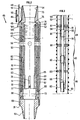
Sur la figure 1 le puits, comportant une partie fortement inclinée sur la verticale, voire horizontale, et équipé d'un dispositif selon l'invention, est exploité à partir de la surface du sol. Ce puits 1 comporte sur une certaine longueur un cuvelage 2 à l'intérieur duquel se trouve un tubage 3 et un conduit 4, qui traverse des formations géologiques dont on veut produire des fluides.In FIG. 1, the well, comprising a part which is strongly inclined towards the vertical, even horizontal, and equipped with a device according to the invention, is operated from the surface of the ground. This well 1 comprises over a certain length a casing 2 inside which is a
De manière à produire sélectivement des fluides des formations géologiques, suivant des zones dites de production 30, 31, 32, 33, on dispose, d'une part, entre le cuvelage 2 et les formations des moyens d'étanchéité 7, 8, 9 du type packer et, d'autre part, entre le cuvelage 2 et le premier tubage 3 et le conduit 4 des moyens d'étanchéité internes au cuvelage. Ces moyens internes 6a, 7a, 8a, 9a sont situés respectivement sensiblement au droit des joints les 7, 8, 9 et sont par exemple du type packer double.So as to selectively produce fluids from geological formations, according to so-called
Chacune des zones de production 30, 31, 32 communique avec des zones intérieures au cuvelage 2 par des orifices 13, 15, 17 respectivement. On peut faire communiquer cette zone à volonté avec l'intérieur du premier tubage 3 par des vannes de circulation, telles des vannes à chemises coulissantes 14, 16, 18 respectivement.Each of the
En production, les vannes 14, 16, 18 sont normalement dotées de clapets anti-retour empêchant la circulation de fluide du tubage vers les formations, mais on pourra très bien supprimer ces clapets, lorsque, par exemple, on voudra procéder à la fracturation d'une zone.In production,
L'extrémité inférieure du conduit 4, comportent une vanne 11 pouvant être commandée à distance, telle qu'une vanne à chemise coulissante semblable aux vannes 14, 16, 18 et permettant de mettre en communication la partie inférieure 33 du puits 1 avec le tubage 3 et le conduit 4, soit pour produire les fluides du fond du puits (par le conduit 4), soit pour les besoins de l'exploitation normale du puits.The lower end of the conduit 4 comprises a valve 11 which can be controlled remotely, such as a sliding jacket valve similar to the
Le conduit 4 relié au tubage 3 par l'élément de liaison hydraulique 12 comporte, si besoin est, disposée à la profondeur requise, une pompe 19 de circulation qui aspire le fluide des formations et le refoule à la surface du sol par la bouche 20. La pompe 19 peut être une pompe hydraulique, électrique ou mécanique, telle le plongeur d'une pompe à tige et balancier. La position de la pompe 19 dans le puits pourra être située sensiblement au dessous du niveau dynamique d'une formation en production. Selon l'invention le sens de circulation du fluide de la pompe peut être unique et ascendant.The conduit 4 connected to the
L'extrémité intérieure et inférieure du tubage 3 comporte un premier organe de connexion 10 relié par des lignes électriques 40 à des instruments et/ou outils 34, 35, 36, 37 disposés dans chacunes des zones de production 30, 31, 32, 33.The inner and lower end of the
Ce premier organe de connexion 10 est adapté à coopérer avec un deuxième organe de connexion 21 relié à la surface du sol par un câble de transmission 22. Ce deuxième organe de connexion 21 est introduit dans le tubage 3 à sa partie supérieure, puis est déplacé jusqu'au deuxième organe de connexion 10 pour établir la coopération de ces derniers.This
Le deuxième organe de connexion 21 peut comporter une barre de charge 21a qui permet la descente par gravité du ce deuxième organe 21, notamment pour les puits verticaux ou faiblement déviés de la verticale. Cet organe 21 peut aussi comporter des garnitures adaptées à coopérer avec l'intérieur de tubage 3, notamment pour les puits fortement déviés de la verticale voir horizontaux ou encore remontant, afin de réaliser une étanchéité et ainsi mouvoir cet organe 21 par un pompage hydraulique produit, soit par la station 29 qui est reliée au tubage 3 par une canalisation 28, soit par la pompe de circulation 19 située dans le conduit 4.The
L'extrémité du tubage comporte un canal 12a, situé en dessous de la liaison hydraulique 12 et qui permet une circulation de fluide, cette liaison hydraulique étant adaptée à permettre l'évacuation des boues ou autres sédiments et étant également adaptée à permettre l'élimination du fluide présent entre les premier 10 et deuxième 21 organes, notamment lors de leur connexion, et grâce à une section convenable. La liaison hydraulique 12 est aussi adaptée à permettre l'amortissement de l'inertie du deuxième organe 21 au cours de sa connexion avec le premier organe 10.The end of the casing comprises a
Pour réaliser la descente du deuxième organe 21 de connexion par un pompage hydraulique d'un fluide, tel une huile dégazée, l'extrêmité supérieure du tubage 3 comporte un presse-étoupe 23 au travers duquel passe le câble de transmission 22 avant d'être renvoyé par deux poulies 24, 25 vers le treuil 26 commandé par le poste 27.To lower the
Lorsque l'on effectue la production d'un puits 1, tel celui foré dans des formations géologiques comportant des hydrocarbures, le puits 1 est équipé d'au moins un tubage 3 et un conduit 4 pour des raisons de sécurité, de manière à éviter une circulation de fluide entre le cuvelage 2 et le tubage 3. Ainsi, lorsque l'on déplace le deuxième organe 21 de connexion, le fluide présent sous celui-ci remonte par le conduit 4. On ne sortira pas du cadre de l'invention, notamment lors de la production à partir d'un puits, en reliant la liaison hydraulique 12 à l'espace annulaire situé entre le tubage 3 et le cuvelage 2 et en supprimant le conduit 4.When producing a well 1, such as that drilled in geological formations comprising hydrocarbons, well 1 is equipped with at least one
Le deuxième organe 10 de connexion est relié aux instruments de mesures 34, 35, 36, 37 respectivement, disposés dans les zones de complétion 30, 31, 32, 33, au moyen des lignes électriques 38, 39, 40, 41. Ces instruments 34, 35, 36, 37 sont adaptés à mesurer le débit de fluide traversant les vannes 14, 16, 18, 11 respectivement, la température et la pression des fluides dans chacunes des zones de complétion 30, 31, 32, 33 respectivement. On pourra, de la même manière qui l'on effectue les mesures de pression, de débit et de température, effectuer toutes autres sortes de mesures physiques et/ou chimique et/ou physico-chimique, telles que la résistivité des fluides des zones de production. En réalisant la liaison électrique entre les appareils de mesures et la surface, il est possible d'obtenir à tout moment et en temps réel les caractéristiques des fluides de chacune des zones et ainsi établir au mieux un programme de production en intervenant sur les vannes 14, 16, 18, 11 de chacune des zones. Par exemple, lorsque le câble de transmission ne comporte qu'un seul conducteur, on pourra utiliser un dispositif multiplex pour regrouper les informations provenant des instruments de mesure.The second connecting
Les vannes 14, 16, 18 sont sélectivement commandées depuis la surface du sol, soit par des outils à clés (21, 21a), soit par une commande hydraulique. Ces outils à clés sont maniés au câble pour les puits verticaux ou faiblement déviés, ou avec des moteurs hydrauliques pour les puits admettant une circulation hydraulique, telle qu'on le pratique avec la technique dite T.F.L. (de l'anglais "Through Flow Line"), ou tout autre moyen, tel celui de la demande de brevet français EN - 87/11 749.The
La figure 2 montre en détail une vanne 45 hydraulique à chemise coulissante 46, 47 adaptée à la production sélective d'un puits selon l'invention. Cette vanne 45 permet de mettre en communication ou non l'extérieur et l'intérieur du tubage.FIG. 2 shows in detail a
Une ligne hydraulique 49, assurant la source d'énergie des éléments de puissance, tels de éléments similaires à la vanne 45, communique par un branchement 50 avec la vanne 45. Sur ce branchement 50 sont disposés des moyens de distribution, tels une électrovanne 51, reliés par un câble électrique 48 à la prise 10 placée à l'extrémité inférieure du tubage 3 (figure 1).A
Cette électrovanne 45 assure l'ouverture et la fermeture de la communication entre la ligne hydraulique 45 et la chambre 52 de poussée hydraulique de la chemise coulissante hydraulique 46.This
Le vanne 45 comporte un corps 53 extérieur cylindrique intercalé dans le tubage 3 grâce à un raccord conique femelle 54 et un raccord conique mâle 55 respectivement disposés en haut et en bas de la vanne.The
Dans ce corps 53 réalisant l'enveloppe extérieure de la vanne sont disposés, sensiblement dans le même plan perpendiculaire à l'axe du tubage, quatre orifices 56 obturables modifiant la communication entre l'intérieur et l'extérieur du tubage.In this
L'obturation des orifices 56 est réalisée au moyen du coulissement de la chemise hydraulique 46 ou de la chemise de sécurité 47.The
Une allonge 57, séparant les chemises 46 et 47, définit avec la chemise hydraulique 46 et la corps 53 la chambre 52 hydraulique de poussée, et assure le guidage des chemises 46 et 47.An
La chemise hydraulique 46 coulisse entre deux positions extrêmes définies d'une part par la coopération d'une butée d'ouverture 58 avec l'embout supérieur 59 de la chemise hydraulique 46, et d'autre part par la coopération d'un talon 60 d'une rainure 61 pratiquée à la partie inférieure de la chemise hydraulique 46 avec le talon 62 de la clavette 63. La clavette 63 est solidaire de l'allonge 57 et en coopérant avec la rainure 61 positionne en rotation la chemise hydraulique 46 par rapport au corps 53 de la vanne.The
Un ressort de rappel 64, coopérant avec l'embout inférieur 65 de la chemise hydraulique 46 et un épaulement 66 de l'allonge 57, assure le retour à la position repos de la chemise hydraulique 46 lorsque la pression à l'intérieur de la chambre de poussée 52 devient inférieure à une valeur prédéterminée.A
L'espace cylindrique 67 défini par l'épaulement 66, l'embout inférieur 65, le corps 53 et l'allonge 57, et dans lequel est placé le ressort 64, débouche à l'intérieur du tubage par un orifice 68 inférieur de circulation et par un orifice 69 supérieur de circulation, une gorge 70 et des ajourages pratiqués dans la chemise 47 de sécurité, de manière à permettre une circulation de fluide et à éviter le colmatage du ressort 64. Au lieu de faire déboucher cet espace cylindrique 67 dans l'intérieur du tubage, on pourra connecter cet espace 67 avec une chambre de compensation remplie avec un fluide restant propre, tel de l'huile.The
A l'intérieur de l'allonge cylindrique 57, coulisse la chemise 47 de sécurité, entre deux positions définies par la coopération d'une lame élastique 71 comportant un ergot avec deux rainures annulaires intérieures 72, 73 usinées dans l'allonge 57 et assignant à la chemise 47 une position haute et une position basse correspondant respectivement à l'ouverture et la fermeture des orifices 56.Inside the
La chemise 47 de sécurité est commandée par un siège de clé 74 adapté à coopérer avec la pène d'un outil circulant dans le tubage. La partie supérieure 75 du corps 53 de vanne, comporte au niveau de la chemise 47 de sécurité un chanfrein 76 adapté au dégagement du pène. La chemise 47 est positionnée en rotation par rapport au corps 53 au moyen d'un ergot 77 solidaire de l'allonge 57 et coopérant avec une rainure 78 pratiquée dans la chemise 47.The
L'extrémité inférieure de la vanne 45 comporte un embout 79 fixé au corps 53 par un filetage 80, l'embout étant muni du raccord conique mâle 55.The lower end of the
Sur le figure 2, la vanne 45 est représentée "normalement ouverte", c'est-à-dire que lorsque la pression du fluide agissant sur la chemise 46 hydraulique est inférieure à une valeur déterminée, les orifices disposés dans le corps de vanne ne sont pas obstrués par la chemise 46 du fait de la force de rappel du ressort 64 qui fait coopérer la butée d'ouverture 58 avec l'embout supérieur 59 de la chemise hydraulique 46.In FIG. 2, the
On ne sortira pas du cadre de l'invention en réalisant et en utilisant une vanne "normalement fermée". Pour cela, il suffit par exemple de relever les orifices pratiqués dans la chemise hydraulique 46 d'une manière telle que, lorsque la butée d'ouverture 58 coopère avec l'embout supérieur 59, les orifices 56 sont obstrués au niveau de la chemise hydraulique 46 et de manière que lorsque le talon 60 de la rainure 61 coopère avec le talon 62 de la clavette 63, les orifices 56 sont libres au niveau de la chemise hydraulique 46.It will not depart from the scope of the invention to produce and use a "normally closed" valve. For this, it suffices for example to raise the orifices made in the
La chambre de poussée 52 correspond à un réservoir adapté à contenir une masse variable de fluide hydraulique.The
La fermeture des orifices de la vanne 45 s'effectue en commandant par la ligne électrique 48 l'ouverture des moyens de distribution 51, en mettant une pression adaptée dans la ligne 49, de manière à créer un écoulement de fluide dans un premier sens et faire ainsi descendre la chemise 46.The orifices of the
Pour immobiliser la chemise 46 dans les positions où les orifices sont ouverts ou fermés, quelle que soit la pression dans la ligne 49, on ferme les moyens de distribution 51.To immobilize the
L'ouverture des orifices de la vannes 45 s'effectue en ouvrant les moyens de distribution 51, de manière à mettre en communication la chambre de poussée 52 avec la ligne hydraulique et en mettant une pression adaptée dans la ligne 49, de manière à créer un écoulement de fluide dans un deuxième sens opposé au premier sens et faire ainsi remonter la chemise 46, cette pression étant inférieure à la pression de fermeture des orifices.The orifices of the
La figure 3 montre shématiquement un dispositif comportant des outils et/ou instruments hydrauliques 81, 82, 83 disposés sur un tubage 90 placé dans le puits 1, le dispositif étant notamment adapté à la production sélective de différentes zones, telles les zones 30, 31, 32, 33 de la figure 1 ou 84, 85, 86 de la figure 3. Ces outils et/ou instruments peuvent être, par exemple des vannes illustrées par la figure 2. Les zones 84, 85, 86 sont respectivement délimitées par des éléments d'étanchéités 87-88, 88-89, 89 et le fond du puits.FIG. 3 schematically shows a device comprising hydraulic tools and / or
Le dispositif comporte une première ligne 91 et éventuellement une deuxième ligne hydraulique 92, ces lignes étant reliées aux outils et/ou instruments par des branchements 93, 94 respectivement. Sur les branchements 93 de la première ligne hydraulique 91 sont disposés des moyens de distribution.The device comprises a
Des moyens de distribution des branchements 93 sont commandés par une ligne électrique 95 reliée à un premier organe 96 de connexion électrique disposé à la partie inférieure et intérieure du tubage et adapté à coopérer avec un deuxième organe de connexion électrique complémentaire relié à la surface du sol par un câble de transmission 22 (figure 1). Tout comme les moyens de distribution sont commandés par une ligne électrique 95, on pourra commander ces moyens par des lignes de commande hydraulique reliées, par exemple, à un organe de connexion de commande hydraulique.Means for distributing the
La première ligne 91 et éventuellement la deuxième ligne hydraulique 92 sont reliées à générateur d'énergie hydraulique disposé soit à la surface du sol, soit au voisinage des outils et/ou instruments.The
Le câble de transmission pourra comporter une ligne électrique de puissance permettant d'alimenter un générateur d'énergie hydraulique disposé au voisinage des outils et/ou instruments.The transmission cable may include an electric power line making it possible to supply a hydraulic energy generator placed in the vicinity of the tools and / or instruments.
La première ligne 91 et éventuellement la deuxième ligne hydraulique 92 pourront être reliées à un organe de connexion hydraulique disposé à l'intérieur du tubage à sa partie inférieure, de la même manière que la ligne électrique 95 est reliée à l'organe de connexion électrique, cet organe de connexion hydraulique coopérant avec un organe complémentaire relié à la surface du sol par une canalisation hydraulique.The
Ces organes de connexion hydrauliques et électriques pourront être associés dans une même organe de connexion, et de même ces lignes hydrauliques et électriques pourront être associées dans une même ligne.These hydraulic and electrical connection members may be associated in the same connection member, and likewise these hydraulic and electrical lines may be associated in the same line.
Pour commander hydrauliquement et sélectivement, par deux sens de circulation de fluide, au moins deux outils et/ou instruments 81, 82, 83 à l'aide seulement d'une ligne hydraulique, on utilise des outils et/ou instruments pourvus de moyens de rappel permettant de revenir dans une position initiale lorsque la pression a décru et on utilise des moyens de distribution disposés sur des branchements 93 de la première ligne 91 hydraulique avec les outils et/ou instruments.To control hydraulically and selectively, by two directions of fluid circulation, at least two tools and / or
Pour mettre en action un premier outil et/ou instrument :
- on ferme les moyens de distribution du deuxième desdits deux outils et/ou instruments ou des autres outils et/ou instruments de manière à réduire, voire stopper, une circulation de fluide dans le branchement du deuxième outil et/ou instrument,
- on ouvre les moyens de distribution du premier outil et/ou instrument de manière à accroitre, la circulation de fluide dans le branchement du premier outil et/ou instrument, et
- on met une pression dans la première
ligne 91 hydraulique de manière à créer, dans le branchement du premier outil et/ou instrument, un écoulement du fluide allant dans un premier sens.
- the means for distributing the second of said two tools and / or instruments or other tools and / or instruments are closed so as to reduce, or even stop, a circulation of fluid in the connection of the second tool and / or instrument,
- the distribution means of the first tool and / or instrument are opened so as to increase the circulation of fluid in the connection of the first tool and / or instrument, and
- pressure is put in the first
hydraulic line 91 so as to create, in the connection of the first tool and / or instrument, a flow of the fluid going in a first direction.
Lorsque l'on veut stopper l'écoulement de fluide, comme cela peut-être les cas pour verrouiller une vanne, on ferme les moyens de distribution du premier outil et/ou instrument.When it is desired to stop the flow of fluid, as may be the case for locking a valve, the distribution means of the first tool and / or instrument are closed.
Pour produire un écoulement dans le branchement du premier outil et/ou instrument suivant un deuxième sens, opposé au premier sens, et de cette manière manoeuvrer le premier outil et/ou instrument, on ouvre les moyens de distribution du premier outil et/ou instrument, on relâche la pression dans la première ligne hydraulique.To produce a flow in the connection of the first tool and / or instrument in a second direction, opposite to the first direction, and this way maneuvering the first tool and / or instrument, the distribution means of the first tool and / or instrument are opened, the pressure in the first hydraulic line is released.
En produisant sélectivement un écoulement dans le branchement d'un outil et/ou instrument, suivant deux sens, il est ainsi possible de manoeuvrer indépendamment toutes sortes d'outil ou d'instrument et notamment des vannes.By selectively producing a flow in the connection of a tool and / or instrument, in two directions, it is thus possible to independently operate all kinds of tool or instrument and in particular valves.
De la même manière que l'on a manoeuvré le premier outil et/ou instrument, on peut manoeuvrer autant d'outils et/ou instruments que l'on voudra.In the same way as one has maneuvered the first tool and / or instrument, one can maneuver as many tools and / or instruments as one wishes.
Pour commander hydrauliquement et sélectivement, suivant deux sens de circulation de fluide, au moins deux outils et/ou instruments 81, 82, 83, à l'aide de deux lignes hydraulique seulement, on utilise une première ligne hydraulique 91 comportant des branchements 93 avec les outils et/ou instruments, la circulation dans ces branchements étant contrôlée par des moyens de distribution placés sur chacun de ces branchements, et une deuxième ligne hydraulique 92 comportant des branchements avec les outils et/ou instruments.To control hydraulically and selectively, in two directions of fluid circulation, at least two tools and / or
Pour mettre en action un premier outil et/ou instrument, on ferme les moyens de distribution du deuxième desdits deux outils et/ou instruments, de manière à réduire voire à stopper, une circulation de fluide dans les branchements du deuxième outil et/ou instrument :
- on ouvre les moyens de distribution du premier outil et/ou instrument de manière à accroître, la circulation de fluide dans le branchement du premier outil et/ou instrument, et
- on met, dans ladite première et/ou deuxième ligne, des pressions adaptées à créer une circulation du fluide dans le branchement avec la première ligne, suivant le premier et/ou le deuxième sens.
- the distribution means of the first tool and / or instrument are opened so as to increase the circulation of fluid in the connection of the first tool and / or instrument, and
- one puts, in said first and / or second line, pressures adapted to create a circulation of the fluid in the connection with the first line, according to the first and / or the second direction.
Pour permettre la circulation de fluide suivant le premier ou le deuxième sens de circulation, comme cela peut être le cas pour ouvrir ou fermer la vanne 45, on réalise une différence de pression positive ou négative entre la première et la deuxième lignes.To allow the circulation of fluid in the first or second direction of circulation, as may be the case for opening or closing the
De la même manière que l'on a commandé le premier outil et/ou instrument indépendamment du deuxième, on pourra commander indépendamment les uns des autres toutes sortes d'outils et/ou instruments.In the same way that one ordered the first tool and / or instrument independently of the second, one can control independently of each other all kinds of tools and / or instruments.
Claims (12)
- A method for carrying out tasks and/or operations, such as taking measurements, in a well (1) having a tubing (34) of a lesser diameter than that of the well, the well being drilled in geological formations and having at least two separate zones (30, 31, 32, 33) for producing fluid, the zones communicating with the well (1), wherein the method comprises the following stages:- the production zones (30, 31, 32, 33) are insulated from one another by sealing means (7, 8, 9),- each of the fluid production zones (30, 31, 32, 33) is equipped with at least one instrument and/or tool (11, 14, 16, 18, 34, 35, 36, 37) adapted to perform tasks and/or operations in relation to the fluid,- the tubing (3) is provided with a first connecting element (10) that may be used in a liquid medium,- the instruments and/or tools are connected to the first connecting element (10) by means of lines (4),- a transmission cable (22) provided with a second connecting element (21) adapted to form a connection with the first connecting element (10) is introduced into the tubing (3),- the second connecting element (21) is moved into a position in which it co-operates with the first element (10), and- the tasks and/or operations are performed by controlling the tools and/or instruments through he transmission cable.
- Method in accordance with claim 1, characterised in that the tools and/or instruments are locked to the tubing (3).
- Method in accordance with one of claims 1 to 2, characterised in that at least one of the instruments (34, 35, 36, 37) is adapted to measure the physical and/or chemical and/or physical-chemical characteristics of the fluids present in a production zone.
- Method in accordance with one of claims 1 to 3, characterised in that at least one of the tools (11, 14, 16, 18) is adapted to modify the fluid flow in a production zone (30, 31, 32, 33).
- Method in accordance with one of claims 1 to 4, characterised in that the first connecting element (10) is located at the lower end of the tubing (3).
- Method in accordance with one of claims 1 to 5, characterised in that the production zones are worked selectively by transferring the fluid produced through the inside the tubing (3).
- Method in accordance with one of claims 1 to 6, characterised in that a pipe (4) adapted to communicate with the lower end of the tubing (3) by means of a hydraulic connection (12) and/or a channel 12a is placed in the well (1), this connection (12) and this channel (12a) being located in the vicinity of the first connecting element.
- Device for performing tasks and/or operations, such as taking measurements, in a well (1) comprising a tubing (3) of a diameter less than that of the well, the well being drilled in geological formations and having at least two separate fluid production zones (30, 31, 32, 33), the zones being in communication with the well and being insulated each from the other by sealing means (7, 8, 9), characterised in that the tubing has in its interior a first connecting element (10) that may be used in a liquid medium, the first connecting element being connected by lines (40) to eat least one instrument and/or tool (11, 14, 16, 18, 34, 35, 36, 37) located in each of the production zones, the instrument and/or tool being adapted to perform tasks and/or operations in relation to the fluid, the first connecting element (10) being adapted to co-operate with a second connecting element (21) connected by a transmission cable (22) to the ground surface, the tubing being adapted to permit the second element to be lowered from the surface and connected to the first element.
- Device in accordance with claim 8, characterised in that the tools and/or instruments are locked to the tubing (3).
- Device in accordance with one of claims 8 or 9, characterised in that the tubing (3) has means (11, 14, 16, 18) that will permit selective communication of the zones with the inside of the tubing (3).
- Device in accordance with one of claims 8 and 10, characterised in that the first connecting element (10) is located at the lower end of the tubing (3).
- Device in accordance with one of claims 8 to 11, characterised in that it comprises a pipe (4) communicating with the tubing substantially at the level of the first connecting element and having its outlet at the ground surface.
Applications Claiming Priority (2)
| Application Number | Priority Date | Filing Date | Title |
|---|---|---|---|
| FR8801089A FR2626613A1 (en) | 1988-01-29 | 1988-01-29 | DEVICE AND METHOD FOR PERFORMING OPERATIONS AND / OR INTERVENTIONS IN A WELL |
| FR8801089 | 1988-01-29 |
Publications (2)
| Publication Number | Publication Date |
|---|---|
| EP0326492A1 EP0326492A1 (en) | 1989-08-02 |
| EP0326492B1 true EP0326492B1 (en) | 1993-04-28 |
Family
ID=9362784
Family Applications (1)
| Application Number | Title | Priority Date | Filing Date |
|---|---|---|---|
| EP89400227A Expired - Lifetime EP0326492B1 (en) | 1988-01-29 | 1989-01-27 | Device and method for carrying out operations and/or interventions in a well |
Country Status (7)
| Country | Link |
|---|---|
| US (1) | US4942926A (en) |
| EP (1) | EP0326492B1 (en) |
| CA (1) | CA1315190C (en) |
| DE (1) | DE68906170T2 (en) |
| DK (1) | DK38389A (en) |
| FR (1) | FR2626613A1 (en) |
| NO (1) | NO180464C (en) |
Cited By (1)
| Publication number | Priority date | Publication date | Assignee | Title |
|---|---|---|---|---|
| CN101936134A (en) * | 2009-01-22 | 2011-01-05 | 普拉德研究及开发股份有限公司 | When drilling well, select optimum well track |
Families Citing this family (62)
| Publication number | Priority date | Publication date | Assignee | Title |
|---|---|---|---|---|
| FR2668793B1 (en) * | 1990-11-02 | 1995-12-15 | Inst Francais Du Petrole | IMPROVED DEVICE FOR INTERVENTING IN NON-ERUPTIVE DEVICE PRODUCTION WELLS. |
| GB9025230D0 (en) * | 1990-11-20 | 1991-01-02 | Framo Dev Ltd | Well completion system |
| US5607018A (en) * | 1991-04-01 | 1997-03-04 | Schuh; Frank J. | Viscid oil well completion |
| US5289881A (en) * | 1991-04-01 | 1994-03-01 | Schuh Frank J | Horizontal well completion |
| NO179112C (en) * | 1991-10-11 | 1996-08-07 | Statoil As | Tool device and method for performing downhole operations |
| US5477923A (en) * | 1992-08-07 | 1995-12-26 | Baker Hughes Incorporated | Wellbore completion using measurement-while-drilling techniques |
| US5547029A (en) * | 1994-09-27 | 1996-08-20 | Rubbo; Richard P. | Surface controlled reservoir analysis and management system |
| US5906238A (en) | 1996-04-01 | 1999-05-25 | Baker Hughes Incorporated | Downhole flow control devices |
| US6237683B1 (en) * | 1996-04-26 | 2001-05-29 | Camco International Inc. | Wellbore flow control device |
| GB2343209B (en) * | 1997-07-10 | 2001-11-07 | Camco Int | Single-phase annulus-operated sliding sleeve |
| WO1999007975A1 (en) * | 1997-08-08 | 1999-02-18 | Baker Hughes Incorporated | Method and apparatus for drilling and completing wells |
| US6039544A (en) * | 1998-02-27 | 2000-03-21 | Jerry Alexander | Oil lift system |
| US6659184B1 (en) | 1998-07-15 | 2003-12-09 | Welldynamics, Inc. | Multi-line back pressure control system |
| US6179052B1 (en) * | 1998-08-13 | 2001-01-30 | Halliburton Energy Services, Inc. | Digital-hydraulic well control system |
| US6567013B1 (en) | 1998-08-13 | 2003-05-20 | Halliburton Energy Services, Inc. | Digital hydraulic well control system |
| US6257338B1 (en) * | 1998-11-02 | 2001-07-10 | Halliburton Energy Services, Inc. | Method and apparatus for controlling fluid flow within wellbore with selectively set and unset packer assembly |
| US6712154B2 (en) * | 1998-11-16 | 2004-03-30 | Enventure Global Technology | Isolation of subterranean zones |
| US6634431B2 (en) * | 1998-11-16 | 2003-10-21 | Robert Lance Cook | Isolation of subterranean zones |
| US7357188B1 (en) | 1998-12-07 | 2008-04-15 | Shell Oil Company | Mono-diameter wellbore casing |
| US6557640B1 (en) * | 1998-12-07 | 2003-05-06 | Shell Oil Company | Lubrication and self-cleaning system for expansion mandrel |
| US6823937B1 (en) | 1998-12-07 | 2004-11-30 | Shell Oil Company | Wellhead |
| US6745845B2 (en) * | 1998-11-16 | 2004-06-08 | Shell Oil Company | Isolation of subterranean zones |
| US6302216B1 (en) | 1998-11-18 | 2001-10-16 | Schlumberger Technology Corp. | Flow control and isolation in a wellbore |
| US6725919B2 (en) * | 1998-12-07 | 2004-04-27 | Shell Oil Company | Forming a wellbore casing while simultaneously drilling a wellbore |
| US6148925A (en) * | 1999-02-12 | 2000-11-21 | Moore; Boyd B. | Method of making a conductive downhole wire line system |
| AU770359B2 (en) * | 1999-02-26 | 2004-02-19 | Shell Internationale Research Maatschappij B.V. | Liner hanger |
| US6332499B1 (en) | 1999-11-23 | 2001-12-25 | Camco International, Inc. | Deployment tubing connector having internal electrical penetrator |
| US6298921B1 (en) | 1999-11-23 | 2001-10-09 | Camco International, Inc. | Modular system for deploying subterranean well-related equipment |
| US6545221B1 (en) | 1999-11-23 | 2003-04-08 | Camco International, Inc. | Splice system for use in splicing coiled tubing having internal power cable |
| US6302203B1 (en) | 2000-03-17 | 2001-10-16 | Schlumberger Technology Corporation | Apparatus and method for communicating with devices positioned outside a liner in a wellbore |
| US7793721B2 (en) | 2003-03-11 | 2010-09-14 | Eventure Global Technology, Llc | Apparatus for radially expanding and plastically deforming a tubular member |
| US7775290B2 (en) | 2003-04-17 | 2010-08-17 | Enventure Global Technology, Llc | Apparatus for radially expanding and plastically deforming a tubular member |
| US7918284B2 (en) | 2002-04-15 | 2011-04-05 | Enventure Global Technology, L.L.C. | Protective sleeve for threaded connections for expandable liner hanger |
| WO2003086675A2 (en) | 2002-04-12 | 2003-10-23 | Enventure Global Technology | Protective sleeve for threaded connections for expandable liner hanger |
| US6722439B2 (en) * | 2002-03-26 | 2004-04-20 | Baker Hughes Incorporated | Multi-positioned sliding sleeve valve |
| AU2003265452A1 (en) | 2002-09-20 | 2004-04-08 | Enventure Global Technology | Pipe formability evaluation for expandable tubulars |
| US7886831B2 (en) | 2003-01-22 | 2011-02-15 | Enventure Global Technology, L.L.C. | Apparatus for radially expanding and plastically deforming a tubular member |
| US7712522B2 (en) | 2003-09-05 | 2010-05-11 | Enventure Global Technology, Llc | Expansion cone and system |
| GB2407595B8 (en) * | 2003-10-24 | 2017-04-12 | Schlumberger Holdings | System and method to control multiple tools |
| US7819185B2 (en) | 2004-08-13 | 2010-10-26 | Enventure Global Technology, Llc | Expandable tubular |
| US7331398B2 (en) * | 2005-06-14 | 2008-02-19 | Schlumberger Technology Corporation | Multi-drop flow control valve system |
| CA2593585C (en) * | 2006-07-24 | 2012-10-02 | Uti Limited Partnership | In situ heavy oil and bitumen recovery process |
| WO2010024818A1 (en) * | 2008-08-29 | 2010-03-04 | Welldynamics, Inc. | Bypass of damaged lines in subterranean wells |
| US20100051269A1 (en) * | 2008-08-29 | 2010-03-04 | Welldynamics, Inc. | Bypass of damaged lines in subterranean wells |
| US9228423B2 (en) * | 2010-09-21 | 2016-01-05 | Schlumberger Technology Corporation | System and method for controlling flow in a wellbore |
| WO2012166627A2 (en) * | 2011-05-27 | 2012-12-06 | Rem Scientific Enterprises, Inc. | Fluid flow measurement sensor, method, and analysis |
| US9027651B2 (en) | 2010-12-07 | 2015-05-12 | Baker Hughes Incorporated | Barrier valve system and method of closing same by withdrawing upper completion |
| US9051811B2 (en) * | 2010-12-16 | 2015-06-09 | Baker Hughes Incorporated | Barrier valve system and method of controlling same with tubing pressure |
| US8955600B2 (en) | 2011-04-05 | 2015-02-17 | Baker Hughes Incorporated | Multi-barrier system and method |
| US9016372B2 (en) | 2012-03-29 | 2015-04-28 | Baker Hughes Incorporated | Method for single trip fluid isolation |
| US9016389B2 (en) | 2012-03-29 | 2015-04-28 | Baker Hughes Incorporated | Retrofit barrier valve system |
| US9828829B2 (en) | 2012-03-29 | 2017-11-28 | Baker Hughes, A Ge Company, Llc | Intermediate completion assembly for isolating lower completion |
| US9434875B1 (en) | 2014-12-16 | 2016-09-06 | Carbo Ceramics Inc. | Electrically-conductive proppant and methods for making and using same |
| AU2014204024B2 (en) | 2013-01-04 | 2017-10-12 | Carbo Ceramics Inc. | Electrically conductive proppant and methods for detecting, locating and characterizing the electrically conductive proppant |
| US11008505B2 (en) | 2013-01-04 | 2021-05-18 | Carbo Ceramics Inc. | Electrically conductive proppant |
| CN103174399B (en) * | 2013-03-12 | 2015-11-18 | 中国海洋石油总公司 | A kind of down-hole of multi pressure series of strata oil and gas development controls sliding bush apparatus automatically |
| US20160230531A1 (en) * | 2013-10-30 | 2016-08-11 | Halliburton Energy Services Inc. | Abandoned well monitoring system |
| US9551210B2 (en) | 2014-08-15 | 2017-01-24 | Carbo Ceramics Inc. | Systems and methods for removal of electromagnetic dispersion and attenuation for imaging of proppant in an induced fracture |
| WO2016171664A1 (en) | 2015-04-21 | 2016-10-27 | Schlumberger Canada Limited | Multi-mode control module |
| US11047208B2 (en) * | 2017-08-15 | 2021-06-29 | Schlumberger Technology Corporation | Chemical injection system |
| WO2019073289A1 (en) | 2017-10-13 | 2019-04-18 | Abu Dhabi National Oil Company | Method and device for producing fluids or gases from a horizontal well |
| US11885200B2 (en) | 2021-01-26 | 2024-01-30 | Halliburton Energy Services, Inc. | Low power consumption electro-hydraulic system with multiple solenoids |
Family Cites Families (11)
| Publication number | Priority date | Publication date | Assignee | Title |
|---|---|---|---|---|
| US3942374A (en) * | 1968-05-23 | 1976-03-09 | N L Industries, Inc. | Apparatus for the determination of the quantity of oil |
| US3656562A (en) * | 1970-07-13 | 1972-04-18 | Brown Oil Tools | Well perforator with positioning tool |
| FR2501777B1 (en) * | 1981-03-13 | 1986-08-29 | Inst Francais Du Petrole | METHOD AND DEVICE FOR PERFORMING OPERATIONS SUCH AS MEASUREMENTS, SUCH AS MEASUREMENTS, IN WELL PORTIONS INCLUDING VERTICAL OR HORIZONTAL WELLS |
| FR2544013B1 (en) * | 1983-04-07 | 1986-05-02 | Inst Francais Du Petrole | METHOD AND DEVICE FOR PERFORMING MEASUREMENTS OR / AND INTERVENTIONS IN A WELL |
| US4553428A (en) * | 1983-11-03 | 1985-11-19 | Schlumberger Technology Corporation | Drill stem testing apparatus with multiple pressure sensing ports |
| US4541481A (en) * | 1983-11-04 | 1985-09-17 | Schlumberger Technology Corporation | Annular electrical contact apparatus for use in drill stem testing |
| US4767349A (en) * | 1983-12-27 | 1988-08-30 | Schlumberger Technology Corporation | Wet electrical connector |
| US4574892A (en) * | 1984-10-24 | 1986-03-11 | Halliburton Company | Tubing conveyed perforating gun electrical detonator |
| FR2573472B2 (en) * | 1984-11-22 | 1987-01-09 | Inst Francais Du Petrole | METHOD AND DEVICE FOR PERFORMING MEASUREMENTS AND / OR INTERVENTIONS IN A WELL |
| US4753291A (en) * | 1987-01-20 | 1988-06-28 | Atlantic Richfield Company | Modular wireline tool connector with swivel coupling |
| US4759406A (en) * | 1987-02-25 | 1988-07-26 | Atlantic Richfield Company | Wireline tool connector with wellbore fluid shutoff valve |
-
1988
- 1988-01-29 FR FR8801089A patent/FR2626613A1/en active Pending
-
1989
- 1989-01-27 EP EP89400227A patent/EP0326492B1/en not_active Expired - Lifetime
- 1989-01-27 DE DE8989400227T patent/DE68906170T2/en not_active Expired - Fee Related
- 1989-01-27 NO NO890355A patent/NO180464C/en not_active IP Right Cessation
- 1989-01-27 US US07/302,333 patent/US4942926A/en not_active Expired - Lifetime
- 1989-01-27 DK DK038389A patent/DK38389A/en not_active Application Discontinuation
- 1989-01-27 CA CA000589339A patent/CA1315190C/en not_active Expired - Fee Related
Cited By (2)
| Publication number | Priority date | Publication date | Assignee | Title |
|---|---|---|---|---|
| CN101936134A (en) * | 2009-01-22 | 2011-01-05 | 普拉德研究及开发股份有限公司 | When drilling well, select optimum well track |
| CN101936134B (en) * | 2009-01-22 | 2015-04-01 | 普拉德研究及开发股份有限公司 | Selecting optimal wellbore trajectory while drilling |
Also Published As
| Publication number | Publication date |
|---|---|
| DK38389D0 (en) | 1989-01-27 |
| EP0326492A1 (en) | 1989-08-02 |
| NO180464C (en) | 1997-04-23 |
| NO890355L (en) | 1989-07-31 |
| NO180464B (en) | 1997-01-13 |
| DE68906170T2 (en) | 1993-08-05 |
| US4942926A (en) | 1990-07-24 |
| FR2626613A1 (en) | 1989-08-04 |
| DK38389A (en) | 1989-07-30 |
| NO890355D0 (en) | 1989-01-27 |
| CA1315190C (en) | 1993-03-30 |
| DE68906170D1 (en) | 1993-06-03 |
Similar Documents
| Publication | Publication Date | Title |
|---|---|---|
| EP0326492B1 (en) | Device and method for carrying out operations and/or interventions in a well | |
| EP0327432B1 (en) | Process and device for hydraulically and selectively controlling at least two tools or instruments of a device, valve for carrying out this method or for using this device | |
| EP1525371B1 (en) | Telescopic guide line for offshore drilling | |
| EP0134734B1 (en) | Oil well logging method and apparatus | |
| FR2519688A1 (en) | SEALING SYSTEM FOR DRILLING WELLS IN WHICH CIRCULATES A HOT FLUID | |
| FR2504972A1 (en) | UNDERGROUND PRODUCTION TEST HEAD AND FLOW CONTROL DEVICE | |
| EP0307266B1 (en) | Method and apparatus for driving specialised intervention equipment into a borehole with at least one section strongly inclined relative to the vertical | |
| FR2484525A1 (en) | HYDRAULIC CONNECTION APPARATUS AND METHOD, ESPECIALLY FOR SUBMARINE PETROLEUM WELL TEST TRAIN | |
| FR2484524A1 (en) | TEST ROD TRAIN AND OIL WELL TEST METHOD | |
| FR2787505A1 (en) | Undersea well with single bore riser has valve connecting annular space passages between rising column and riser | |
| FR2531483A1 (en) | SYSTEM AND APPARATUS FOR MEASUREMENT DURING DRILLING FOR DRILLING PROBE HOLES | |
| EP0122839A1 (en) | Method and apparatus for conducting logging and/or work-over operations in a borehole | |
| FR2654462A1 (en) | METHOD AND APPARATUS FOR ESTABLISHING COMMUNICATION WITH A BACKGROUND TRUNCON OF SURVEYING A CONTROL FLUID CONDUIT. | |
| EP0059376A1 (en) | Modular installation for subsea oil production | |
| FR2560632A1 (en) | APPARATUS FOR SETTING TOOLS FOR DRILLING, COMPLETING OR RECONDITIONING WELLS AND APPARATUS FOR A FAT VALVE | |
| EP0457879B1 (en) | Device and method for cleaning an underground well | |
| EP0296207B1 (en) | Method and device for taking measurements and/or carrying out interventions in a well subjected to a hydraulic compression | |
| EP0267096B1 (en) | Tool for the measurement of the pressure in an oil well | |
| EP0457653B1 (en) | Safety sleeve and device for wells, particularly for a subterranean reservoir of fluid under pressure | |
| EP1144800A1 (en) | Method and device for adjusting at a set value the bore fluid level in the riser | |
| FR2785963A1 (en) | UNDERWATER DRILL RISING COLUMN VALVE | |
| CA1336882C (en) | Sliding sleeve valve for the production of bored tube wells | |
| CA1325368C (en) | Process and device for hydraulically and selectively controlling at least two tools or instruments of a device | |
| FR2772826A1 (en) | Process for reinforcing at least part of the wall of a shaft | |
| FR2459358A2 (en) | DEVICE AND METHOD FOR ISOLATING A UNDERGROUND AREA CONTAINING A FLUID, IN PARTICULAR FOR RECONDITIONING AN OIL WELL |
Legal Events
| Date | Code | Title | Description |
|---|---|---|---|
| PUAI | Public reference made under article 153(3) epc to a published international application that has entered the european phase |
Free format text: ORIGINAL CODE: 0009012 |
|
| 17P | Request for examination filed |
Effective date: 19890206 |
|
| AK | Designated contracting states |
Kind code of ref document: A1 Designated state(s): DE GB IT NL |
|
| 17Q | First examination report despatched |
Effective date: 19910423 |
|
| ITF | It: translation for a ep patent filed |
Owner name: DE DOMINICIS & MAYER S.R.L. |
|
| GRAA | (expected) grant |
Free format text: ORIGINAL CODE: 0009210 |
|
| AK | Designated contracting states |
Kind code of ref document: B1 Designated state(s): DE GB IT NL |
|
| REF | Corresponds to: |
Ref document number: 68906170 Country of ref document: DE Date of ref document: 19930603 |
|
| GBT | Gb: translation of ep patent filed (gb section 77(6)(a)/1977) |
Effective date: 19930513 |
|
| PGFP | Annual fee paid to national office [announced via postgrant information from national office to epo] |
Ref country code: DE Payment date: 19940207 Year of fee payment: 6 |
|
| PLBE | No opposition filed within time limit |
Free format text: ORIGINAL CODE: 0009261 |
|
| STAA | Information on the status of an ep patent application or granted ep patent |
Free format text: STATUS: NO OPPOSITION FILED WITHIN TIME LIMIT |
|
| 26N | No opposition filed | ||
| PG25 | Lapsed in a contracting state [announced via postgrant information from national office to epo] |
Ref country code: DE Effective date: 19951003 |
|
| REG | Reference to a national code |
Ref country code: GB Ref legal event code: IF02 |
|
| PGFP | Annual fee paid to national office [announced via postgrant information from national office to epo] |
Ref country code: GB Payment date: 20020129 Year of fee payment: 14 |
|
| PGFP | Annual fee paid to national office [announced via postgrant information from national office to epo] |
Ref country code: NL Payment date: 20020131 Year of fee payment: 14 |
|
| PG25 | Lapsed in a contracting state [announced via postgrant information from national office to epo] |
Ref country code: GB Free format text: LAPSE BECAUSE OF NON-PAYMENT OF DUE FEES Effective date: 20030127 |
|
| PG25 | Lapsed in a contracting state [announced via postgrant information from national office to epo] |
Ref country code: NL Free format text: LAPSE BECAUSE OF NON-PAYMENT OF DUE FEES Effective date: 20030801 |
|
| GBPC | Gb: european patent ceased through non-payment of renewal fee | ||
| NLV4 | Nl: lapsed or anulled due to non-payment of the annual fee |
Effective date: 20030801 |
|
| PG25 | Lapsed in a contracting state [announced via postgrant information from national office to epo] |
Ref country code: IT Free format text: LAPSE BECAUSE OF NON-PAYMENT OF DUE FEES;WARNING: LAPSES OF ITALIAN PATENTS WITH EFFECTIVE DATE BEFORE 2007 MAY HAVE OCCURRED AT ANY TIME BEFORE 2007. THE CORRECT EFFECTIVE DATE MAY BE DIFFERENT FROM THE ONE RECORDED. Effective date: 20050127 |