EP0326255A2 - Motor control apparatus - Google Patents
Motor control apparatus Download PDFInfo
- Publication number
- EP0326255A2 EP0326255A2 EP89300346A EP89300346A EP0326255A2 EP 0326255 A2 EP0326255 A2 EP 0326255A2 EP 89300346 A EP89300346 A EP 89300346A EP 89300346 A EP89300346 A EP 89300346A EP 0326255 A2 EP0326255 A2 EP 0326255A2
- Authority
- EP
- European Patent Office
- Prior art keywords
- signal
- circuit
- speed
- rotation control
- drum
- Prior art date
- Legal status (The legal status is an assumption and is not a legal conclusion. Google has not performed a legal analysis and makes no representation as to the accuracy of the status listed.)
- Granted
Links
Images
Classifications
-
- H—ELECTRICITY
- H02—GENERATION; CONVERSION OR DISTRIBUTION OF ELECTRIC POWER
- H02P—CONTROL OR REGULATION OF ELECTRIC MOTORS, ELECTRIC GENERATORS OR DYNAMO-ELECTRIC CONVERTERS; CONTROLLING TRANSFORMERS, REACTORS OR CHOKE COILS
- H02P5/00—Arrangements specially adapted for regulating or controlling the speed or torque of two or more electric motors
-
- G—PHYSICS
- G11—INFORMATION STORAGE
- G11B—INFORMATION STORAGE BASED ON RELATIVE MOVEMENT BETWEEN RECORD CARRIER AND TRANSDUCER
- G11B15/00—Driving, starting or stopping record carriers of filamentary or web form; Driving both such record carriers and heads; Guiding such record carriers or containers therefor; Control thereof; Control of operating function
- G11B15/18—Driving; Starting; Stopping; Arrangements for control or regulation thereof
- G11B15/1808—Driving of both record carrier and head
- G11B15/1875—Driving of both record carrier and head adaptations for special effects or editing
-
- G—PHYSICS
- G11—INFORMATION STORAGE
- G11B—INFORMATION STORAGE BASED ON RELATIVE MOVEMENT BETWEEN RECORD CARRIER AND TRANSDUCER
- G11B15/00—Driving, starting or stopping record carriers of filamentary or web form; Driving both such record carriers and heads; Guiding such record carriers or containers therefor; Control thereof; Control of operating function
- G11B15/18—Driving; Starting; Stopping; Arrangements for control or regulation thereof
- G11B15/46—Controlling, regulating, or indicating speed
- G11B15/467—Controlling, regulating, or indicating speed in arrangements for recording or reproducing wherein both record carriers and heads are driven
- G11B15/473—Controlling, regulating, or indicating speed in arrangements for recording or reproducing wherein both record carriers and heads are driven by controlling the speed of the heads
Definitions
- the present invention relates generally to servo circuits and more particularly to a servo circuit suitable for use in controlling a drum motor of, for example, a video tape recorder.
- a servo circuit is generally used to stabilize the revolution rate of a rotary head (see Japanese Laid-Open Patent Gazette No. 61-39877 and so on).
- Figure 1 of the accompanying drawings illustrates an example of a conventional servo circuit that controls a rotary head drum.
- a rotary head drum 1 which is rotated by a motor 2.
- a frequency generator 3 and a pulse generator 4 are mounted on the peripheral surface of the rotary head drum 1.
- the frequency generator 3 is adapted to generate a frequency signal FG of, for example, 720 Hz at normal running speed or to generate a signal each time the rotary head drum 1 is rotated by a predetermined angle (for example, 15°).
- the pulse generator 4 is adapted to generate a pulse signal of, for example, 30Hz or to generate a pulse signal at every revolution of the rotary head drum 1.
- the signal FG from the frequency generator 3 and the signal PG from the pulse generator 4 are both supplied to a servo signal processor section 5 represented in phantom in Figure 1.
- This servo signal processor section 5 might be formed of an integrated circuit (IC).
- the signal FG supplied to the servo signal processor section 5 is supplied to a cycle detector circuit 6 therein.
- the cycle detector circuit 6 detects the rotational speed of the rotary head drum 1 on the basis of the signal FG and produces a voltage signal corresponding to the detected signal and thereby indicative of the rotational speed of the rotary head drum 1.
- the signal PG supplied to the servo signal processor section 5 is supplied to a first comparing signal input terminal of a phase difference detector circuit 7 therein
- a reference signal generator 8 in the servo signal processor circuit 5 is adapted to generate a reference signal V D synchronized with the vertical synchronizing signal.
- a mode changing signal is supplied through a terminal 8a to the reference signal generator circuit 8 to disconnect the terminal 9 therefrom and the reference signal generator 8 itself generates the reference signal V D .
- the phase difference detector circuit 7 detects a phase difference between the pulse signal PG and the reference signal V D and produces a voltage signal corresponding to the detected phase difference therebetween.
- the voltage signal from the cycle detector circuit 6 is supplied to a plus (+) input terminal of a subtractor circuit 10. Also, a voltage signal corresponding to reference speed data obtained at a terminal 11 is supplied to a minus (-) input terminal of the subtractor circuit 10.
- the subtractor circuit 10 subtracts the voltage signals through the terminal 11 from the voltage signal of the detector circuit 6 to produce a subtracted voltage signal that indicates the difference between the reference speed and the actual speed.
- the subtracted signal is supplied to a first adding signal input terminal of an adder circuit 12 and the voltage signal from the phase difference detector circuit 7 is supplied to a second adding signal input terminal of the adder circuit 12.
- the adder circuit 12 adds the subtracted signal and the voltage signal each other to produce an added signal of the speed difference and the phase difference.
- the added signal from the adder circuit 12 is supplied to a phase compensator circuit 13 and is thereby phase-compensated.
- the output signal from the phase compensator circuit 13 is supplied to a driver circuit 14, and this driver circuit 14 drives the drum motor 2 to rotate the rotary head drum 1.
- the drum motor 2 When the drum motor 2 is servo-controlled in this way, in the recording mode of the video tape recorder, the rotary head drum 1 is controlled to rotate in synchronism with the video signal to be recorded, while upon reproduction the rotary head drum 1 is controlled to rotate in synchronism with the reference signal produced within the video tape recorder.
- the video tape recorder when in the playback mode the video tape recorder performs the variable tape speed reproduction such as a high-speed reproduction and so on, the revolution speed of the rotary head drum 1 has to be varied.
- the frequency of the reference signal V D from the reference signal generator circuit 8 has to be varied, making the reference signal generator circuit 8 complicated in arrangement.
- a servo circuit for controlling a rotation of a drum motor to rotate a rotary head drum comprising: means for generating a frequency signal corresponding to the rotational speed of said drum motor; means for detecting a cycle of said frequency signal from said frequency signal generating means; means for detecting a speed deviation between a detected signal from said detecting means and a reference signal to produce a speed deviation signal; means for generating a first rotation control signal based on said speed deviation signal; means for producing a second rotation control signal based on phase difference data which is provided by integrating said speed deviation signal; and means for adding said first and second rotation control signals to produce a rotation control signal which is supplied to said drum motor.
- a servo circuit in this embodiment is adapted to control the rotation of the rotary head drum 1 on which is mounted a rotary head in a video tape recorder, so this servo circuit is used in the reproduction mode of the video tape recorder.
- FIG 2 shows, there is provided the rotary head drum 1, and the frequency generator 3 is mounted on the peripheral surface of this rotary head drum 1 to generate the frequency signal FG.
- This frequency signal FG is supplied to a servo processor section 20 represented in phantom in figure 2.
- the servo signal processor section 20 might be of an integrated circuit configuration.
- the frequency generator 3 is adapted to generate the frequency signal FG which has one period or cycle for every 15° rotation of the rotary head drum 1. Accordingly, if the rotary dead drum 1 is rotated 30 times per second in its stable state, the frequency of the FG signal produced by generator 3 is 720 Hz.
- the signal FG supplied to the servo signal processor section 20 is supplied to a cycle detector circuit 21 therein.
- the cycle detector circuit 21 detects the revolution speed of the rotary head drum 1 on the basis of the frequency signal FG.
- the detected signal therefrom is supplied to a plus (+) input terminal of a subtractor circuit 22.
- a reference speed signal corresponding to a tape speed of the video tape recorder is applied through a terminal 23 to a minus (-) input terminal of the subtractor circuit 22.
- the subtractor circuit 22 subtracts the reference speed signal from the detected signal to produce a subtracted signal as a speed deviation signal that indicates the difference between the reference speed and the actual rotational speed of the rotary head drum 1.
- the subtracted signal is supplied as the speed deviation signal to a first constant circuit 24.
- This first constant circuit 24 multiplies the speed deviation signal by K0 (which is a constant) to provide a speed control signal which is supplied to a first adding signal input terminal of an adder circuit 27.
- the subtracted signal as the speed deviation signal is supplied to an integrator circuit 25.
- the integrator circuit 25 integrates the speed deviation signal and converts the same into a phase information signal. In other words, the integrator circuit 25 performs the integration expressed by the function
- the phase information signal obtained by the integration is supplied to a second constant circuit 26.
- the second constant circuit 26 multiplies the phase information signal by K1 to produce a phase control signal where K1 is a constant.
- the phase control signal from the second constant circuit 26 is supplied to a second adding signal input terminal of the adder circuit 27.
- the adder circuit 27 adds the speed control signal and the phase control signal to produce a rotation control signal.
- This rotation control signal from the adder circuit 27 is supplied to the driver circuit 14, and the driver circuit 14 drives the drum motor 2 to rotate the rotary head drum 1.
- the speed control signal and the phase control signal are obtained on the basis of the frequency signal FG having a relatively high frequency, for example, 720 Hz.
- the speed control signal and the phase control signal are both generated during a short interval corresponding to the frequency of 720 Hz so that the rotation of the drum motor 2 can be stabilized in a short period of time, resulting in high stability of rotation.
- the reference speed signal supplied to the terminal 23 is varied to a signal corresponding to the playback speed.
- the reference speed signal is a voltage signal
- the voltage value of this voltage signal is changed without need to change an oscillation frequency or the like unlike the prior art.
- the servo signal processor section 20 can be simplified in arrangement.
- the rotation of the drum motor can be stabilized in a short period of time. Further, the rotational speed can be varied by the simple arrangement and the rotation of the drum motor can be controlled with high stability and with ease.
Abstract
Description
- The present invention relates generally to servo circuits and more particularly to a servo circuit suitable for use in controlling a drum motor of, for example, a video tape recorder.
- In a video tape recorder (VTR) in which a rotary head is mounted on a rotary head drum, a servo circuit is generally used to stabilize the revolution rate of a rotary head (see Japanese Laid-Open Patent Gazette No. 61-39877 and so on).
- Figure 1 of the accompanying drawings illustrates an example of a conventional servo circuit that controls a rotary head drum.
- Referring to Figure 1, there is shown a
rotary head drum 1 which is rotated by amotor 2. Afrequency generator 3 and apulse generator 4 are mounted on the peripheral surface of therotary head drum 1. Thefrequency generator 3 is adapted to generate a frequency signal FG of, for example, 720 Hz at normal running speed or to generate a signal each time therotary head drum 1 is rotated by a predetermined angle (for example, 15°). Thepulse generator 4 is adapted to generate a pulse signal of, for example, 30Hz or to generate a pulse signal at every revolution of therotary head drum 1. - The signal FG from the
frequency generator 3 and the signal PG from thepulse generator 4 are both supplied to a servosignal processor section 5 represented in phantom in Figure 1. This servosignal processor section 5 might be formed of an integrated circuit (IC). The signal FG supplied to the servosignal processor section 5 is supplied to a cycle detector circuit 6 therein. The cycle detector circuit 6 detects the rotational speed of therotary head drum 1 on the basis of the signal FG and produces a voltage signal corresponding to the detected signal and thereby indicative of the rotational speed of therotary head drum 1. The signal PG supplied to the servosignal processor section 5 is supplied to a first comparing signal input terminal of a phasedifference detector circuit 7 therein Areference signal generator 8 in the servosignal processor circuit 5 is adapted to generate a reference signal VD synchronized with the vertical synchronizing signal. When the video tape recorder is operated in the playback mode, a mode changing signal is supplied through aterminal 8a to the referencesignal generator circuit 8 to disconnect the terminal 9 therefrom and thereference signal generator 8 itself generates the reference signal VD. Then, the phasedifference detector circuit 7 detects a phase difference between the pulse signal PG and the reference signal VD and produces a voltage signal corresponding to the detected phase difference therebetween. - The voltage signal from the cycle detector circuit 6 is supplied to a plus (+) input terminal of a
subtractor circuit 10. Also, a voltage signal corresponding to reference speed data obtained at aterminal 11 is supplied to a minus (-) input terminal of thesubtractor circuit 10. Thus, thesubtractor circuit 10 subtracts the voltage signals through theterminal 11 from the voltage signal of the detector circuit 6 to produce a subtracted voltage signal that indicates the difference between the reference speed and the actual speed. The subtracted signal is supplied to a first adding signal input terminal of anadder circuit 12 and the voltage signal from the phasedifference detector circuit 7 is supplied to a second adding signal input terminal of theadder circuit 12. Thus, theadder circuit 12 adds the subtracted signal and the voltage signal each other to produce an added signal of the speed difference and the phase difference. Then, the added signal from theadder circuit 12 is supplied to aphase compensator circuit 13 and is thereby phase-compensated. The output signal from thephase compensator circuit 13 is supplied to adriver circuit 14, and thisdriver circuit 14 drives thedrum motor 2 to rotate therotary head drum 1. - When the
drum motor 2 is servo-controlled in this way, in the recording mode of the video tape recorder, therotary head drum 1 is controlled to rotate in synchronism with the video signal to be recorded, while upon reproduction therotary head drum 1 is controlled to rotate in synchronism with the reference signal produced within the video tape recorder. - However, if a pulse signal PG of about 30 Hz from the
pulse generator 4 is used to detect the phase difference, there is the disadvantage that therotary head drum 1 cannot be rotated stably without taking a relatively long time to stabilise. - Further, when in the playback mode the video tape recorder performs the variable tape speed reproduction such as a high-speed reproduction and so on, the revolution speed of the
rotary head drum 1 has to be varied. In this case, the frequency of the reference signal VD from the referencesignal generator circuit 8 has to be varied, making the referencesignal generator circuit 8 complicated in arrangement. - Accordingly, it is an object of the present invention to provide an improved servo circuit.
- It is another object of the present invention to provide a servo circuit which can control a drum motor to rotate stably.
- It is a further object of the present invention to provide a servo circuit by which a rotation of a drum motor can be stabilised in a short time period.
- According to the present invention, there is provided a servo circuit for controlling a rotation of a drum motor to rotate a rotary head drum comprising:
means for generating a frequency signal corresponding to the rotational speed of said drum motor;
means for detecting a cycle of said frequency signal from said frequency signal generating means;
means for detecting a speed deviation between a detected signal from said detecting means and a reference signal to produce a speed deviation signal;
means for generating a first rotation control signal based on said speed deviation signal;
means for producing a second rotation control signal based on phase difference data which is provided by integrating said speed deviation signal; and
means for adding said first and second rotation control signals to produce a rotation control signal which is supplied to said drum motor. - A better understanding of the objects, features and advantages of the invention can be gained from a consideration of the following detailed description of the preferred embodiment thereof, in conjunction with the figures of the accompanying drawings, wherein
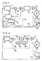
- Figure 1 is a diagram showing an example of a conventional servo circuit; and
- Figure 2 is a diagram showing an embodiment of a servo circuit according to the present invention.
- Now, an embodiment of a servo circuit according to the present invention will hereinafter be described with reference to Figure 2. In Figure 2, like parts corresponding to those of figure 1 are marked with the same references and therefore need not be described in detail.
- Similarly to figure 1, a servo circuit in this embodiment is adapted to control the rotation of the
rotary head drum 1 on which is mounted a rotary head in a video tape recorder, so this servo circuit is used in the reproduction mode of the video tape recorder. - As figure 2 shows, there is provided the
rotary head drum 1, and thefrequency generator 3 is mounted on the peripheral surface of thisrotary head drum 1 to generate the frequency signal FG. This frequency signal FG is supplied to aservo processor section 20 represented in phantom in figure 2. The servosignal processor section 20 might be of an integrated circuit configuration. In this embodiment, thefrequency generator 3 is adapted to generate the frequency signal FG which has one period or cycle for every 15° rotation of therotary head drum 1. Accordingly, if the rotarydead drum 1 is rotated 30 times per second in its stable state, the frequency of the FG signal produced bygenerator 3 is 720 Hz. - The signal FG supplied to the servo
signal processor section 20 is supplied to acycle detector circuit 21 therein. Thecycle detector circuit 21 detects the revolution speed of therotary head drum 1 on the basis of the frequency signal FG. The detected signal therefrom is supplied to a plus (+) input terminal of asubtractor circuit 22. A reference speed signal corresponding to a tape speed of the video tape recorder is applied through aterminal 23 to a minus (-) input terminal of thesubtractor circuit 22. Thus, thesubtractor circuit 22 subtracts the reference speed signal from the detected signal to produce a subtracted signal as a speed deviation signal that indicates the difference between the reference speed and the actual rotational speed of therotary head drum 1. - In this embodiment, the subtracted signal is supplied as the speed deviation signal to a first
constant circuit 24. This firstconstant circuit 24 multiplies the speed deviation signal by K₀ (which is a constant) to provide a speed control signal which is supplied to a first adding signal input terminal of anadder circuit 27. Further, the subtracted signal as the speed deviation signal is supplied to an integrator circuit 25. The integrator circuit 25 integrates the speed deviation signal and converts the same into a phase information signal. In other words, the integrator circuit 25 performs the integration expressed by the function
constant circuit 26. The secondconstant circuit 26 multiplies the phase information signal by K₁ to produce a phase control signal where K₁ is a constant. The phase control signal from the secondconstant circuit 26 is supplied to a second adding signal input terminal of theadder circuit 27. Theadder circuit 27 adds the speed control signal and the phase control signal to produce a rotation control signal. This rotation control signal from theadder circuit 27 is supplied to thedriver circuit 14, and thedriver circuit 14 drives thedrum motor 2 to rotate therotary head drum 1. - When the
rotary head drum 1 is rotated as described above, the speed control signal and the phase control signal are obtained on the basis of the frequency signal FG having a relatively high frequency, for example, 720 Hz. Thus, the speed control signal and the phase control signal are both generated during a short interval corresponding to the frequency of 720 Hz so that the rotation of thedrum motor 2 can be stabilized in a short period of time, resulting in high stability of rotation. - In a variable tape speed playback mode such as a high-speed search mode and so on, it is sufficient that the reference speed signal supplied to the
terminal 23 is varied to a signal corresponding to the playback speed. By way of example, if the reference speed signal is a voltage signal, it is sufficient that the voltage value of this voltage signal is changed without need to change an oscillation frequency or the like unlike the prior art. Thus, the servosignal processor section 20 can be simplified in arrangement. - According to the servo circuit of the present invention, the rotation of the drum motor can be stabilized in a short period of time. Further, the rotational speed can be varied by the simple arrangement and the rotation of the drum motor can be controlled with high stability and with ease.
Claims (8)
means (3) for generating a frequency signal (FG) corresponding to the rotational speed of said drum motor (2);
means (21) for detecting a cycle of said frequency signal (FG) from said frequency signal generating means (3);
means (22) for detecting a speed deviation between a detected signal from said detecting means (21) and a reference signal (23) to produce a speed deviation signal;
means (24) for generating a first rotation control signal based on said speed deviation signal;
means (25, 26) for producing a second rotation control signal based on phase difference data which is provided by integrating said speed deviation signal; and
means (27) for adding said first and second rotation control signals to produce a rotation control signal which is supplied to said drum motor (2).
Applications Claiming Priority (2)
| Application Number | Priority Date | Filing Date | Title |
|---|---|---|---|
| JP15559/88 | 1988-01-26 | ||
| JP63015559A JPH01194881A (en) | 1988-01-26 | 1988-01-26 | Servo-circuit |
Publications (3)
| Publication Number | Publication Date |
|---|---|
| EP0326255A2 true EP0326255A2 (en) | 1989-08-02 |
| EP0326255A3 EP0326255A3 (en) | 1990-01-31 |
| EP0326255B1 EP0326255B1 (en) | 1993-12-15 |
Family
ID=11892114
Family Applications (1)
| Application Number | Title | Priority Date | Filing Date |
|---|---|---|---|
| EP89300346A Expired - Lifetime EP0326255B1 (en) | 1988-01-26 | 1989-01-16 | Motor control apparatus |
Country Status (7)
| Country | Link |
|---|---|
| US (1) | US4902946A (en) |
| EP (1) | EP0326255B1 (en) |
| JP (1) | JPH01194881A (en) |
| KR (1) | KR890012273A (en) |
| CA (1) | CA1329258C (en) |
| DE (1) | DE68911325T2 (en) |
| HK (1) | HK120395A (en) |
Cited By (3)
| Publication number | Priority date | Publication date | Assignee | Title |
|---|---|---|---|---|
| EP0436109A2 (en) * | 1989-12-30 | 1991-07-10 | Sony Corporation | Controller for a rotary drum |
| EP0465015A1 (en) * | 1990-06-22 | 1992-01-08 | Kabushiki Kaisha Toshiba | Digital comb filter |
| GB2337845A (en) * | 1998-05-19 | 1999-12-01 | Mitsubishi Electric Corp | Magnetic recording and reproducing apparatus with electronic adjustment of interval between stationary and rotary heads |
Families Citing this family (3)
| Publication number | Priority date | Publication date | Assignee | Title |
|---|---|---|---|---|
| JPH02197283A (en) * | 1989-01-24 | 1990-08-03 | Canon Inc | Rotation controller |
| KR0181274B1 (en) * | 1990-12-21 | 1999-04-15 | 강진구 | Method for setting variable speed tracking data of vtr |
| JPH04263155A (en) * | 1991-01-11 | 1992-09-18 | Alps Electric Co Ltd | Tension controller of tape player |
Citations (5)
| Publication number | Priority date | Publication date | Assignee | Title |
|---|---|---|---|---|
| EP0055146A1 (en) * | 1980-12-12 | 1982-06-30 | Societe Pour L'etude Et La Fabrication De Circuits Integres Speciaux - E.F.C.I.S. | Frequency-dependent numerical control circuit |
| EP0131316A2 (en) * | 1983-03-15 | 1985-01-16 | Koninklijke Philips Electronics N.V. | System for the reproduction of information signals recorded on magnetic tape |
| EP0227052A1 (en) * | 1982-04-02 | 1987-07-01 | Ampex Systems Corporation | Servo control apparatus |
| EP0239655A1 (en) * | 1986-04-01 | 1987-10-07 | Océ-Nederland B.V. | Electronic proportional-integral-controller in digital execution |
| EP0249465A1 (en) * | 1986-06-10 | 1987-12-16 | Sony Corporation | Motor rotation control apparatus |
Family Cites Families (17)
| Publication number | Priority date | Publication date | Assignee | Title |
|---|---|---|---|---|
| US3577056A (en) * | 1968-03-13 | 1971-05-04 | Sony Corp | Dc motor servosystem |
| JPS51141311A (en) * | 1975-05-30 | 1976-12-06 | Shinko Electric Co Ltd | Speed regulator of a motor speed controller |
| US4337427A (en) * | 1980-04-14 | 1982-06-29 | General Dynamics, Pomona Division | Selective filter for closed loop servo system |
| JPS59142603A (en) * | 1983-02-01 | 1984-08-15 | Sanyo Denki Kk | Control system of high gain feedback |
| US4540923A (en) * | 1984-05-14 | 1985-09-10 | General Motors Corporation | Adaptive servomotor controller |
| JPS60249759A (en) * | 1984-05-23 | 1985-12-10 | Nissan Motor Co Ltd | Controller of continuously variable transmission gear |
| JPS60254201A (en) * | 1984-05-30 | 1985-12-14 | Toshiba Corp | Controller |
| JPS6192181A (en) * | 1984-10-08 | 1986-05-10 | Matsushita Electric Ind Co Ltd | Speed controller of motor |
| JPS61116986A (en) * | 1984-11-09 | 1986-06-04 | Fanuc Ltd | Speed control system |
| JPS61164481A (en) * | 1985-01-12 | 1986-07-25 | Fanuc Ltd | Speed control system |
| US4733149A (en) * | 1985-05-31 | 1988-03-22 | Kollmorgen Technologies Corporation | Adaptive control system |
| JPS626431A (en) * | 1985-06-29 | 1987-01-13 | Toshiba Corp | Magnetic recording medium |
| JPS62126883A (en) * | 1985-11-27 | 1987-06-09 | Fanuc Ltd | Speed control system |
| JPS62147984A (en) * | 1985-12-20 | 1987-07-01 | Nippon Kogaku Kk <Nikon> | Rotary servo-apparatus |
| JPS62189989A (en) * | 1986-02-14 | 1987-08-19 | Fanuc Ltd | Control system of servo motor with armature winding in parallel |
| US4727303A (en) * | 1986-05-22 | 1988-02-23 | Gmf Robotics Corporation | Positional control method and system utilizing same |
| JPS6419989A (en) * | 1987-07-10 | 1989-01-24 | Matsushita Electric Ind Co Ltd | Speed controller for motor |
-
1988
- 1988-01-26 JP JP63015559A patent/JPH01194881A/en active Pending
- 1988-12-09 CA CA000585438A patent/CA1329258C/en not_active Expired - Lifetime
- 1988-12-09 US US07/281,647 patent/US4902946A/en not_active Expired - Lifetime
- 1988-12-20 KR KR1019880017004A patent/KR890012273A/en not_active Application Discontinuation
-
1989
- 1989-01-16 DE DE89300346T patent/DE68911325T2/en not_active Expired - Lifetime
- 1989-01-16 EP EP89300346A patent/EP0326255B1/en not_active Expired - Lifetime
-
1995
- 1995-07-20 HK HK120395A patent/HK120395A/en not_active IP Right Cessation
Patent Citations (5)
| Publication number | Priority date | Publication date | Assignee | Title |
|---|---|---|---|---|
| EP0055146A1 (en) * | 1980-12-12 | 1982-06-30 | Societe Pour L'etude Et La Fabrication De Circuits Integres Speciaux - E.F.C.I.S. | Frequency-dependent numerical control circuit |
| EP0227052A1 (en) * | 1982-04-02 | 1987-07-01 | Ampex Systems Corporation | Servo control apparatus |
| EP0131316A2 (en) * | 1983-03-15 | 1985-01-16 | Koninklijke Philips Electronics N.V. | System for the reproduction of information signals recorded on magnetic tape |
| EP0239655A1 (en) * | 1986-04-01 | 1987-10-07 | Océ-Nederland B.V. | Electronic proportional-integral-controller in digital execution |
| EP0249465A1 (en) * | 1986-06-10 | 1987-12-16 | Sony Corporation | Motor rotation control apparatus |
Cited By (7)
| Publication number | Priority date | Publication date | Assignee | Title |
|---|---|---|---|---|
| EP0436109A2 (en) * | 1989-12-30 | 1991-07-10 | Sony Corporation | Controller for a rotary drum |
| EP0436109A3 (en) * | 1989-12-30 | 1992-10-28 | Sony Corporation | Controller for a rotary drum |
| US5231548A (en) * | 1989-12-30 | 1993-07-27 | Sony Corporation | Rotary drum controller |
| EP0465015A1 (en) * | 1990-06-22 | 1992-01-08 | Kabushiki Kaisha Toshiba | Digital comb filter |
| US5321643A (en) * | 1990-06-22 | 1994-06-14 | Kabushiki Kaisha Toshiba | Digital comb filter |
| GB2337845A (en) * | 1998-05-19 | 1999-12-01 | Mitsubishi Electric Corp | Magnetic recording and reproducing apparatus with electronic adjustment of interval between stationary and rotary heads |
| GB2337845B (en) * | 1998-05-19 | 2000-04-26 | Mitsubishi Electric Corp | Magnetic recording and reproducing apparatus with electronic adjustment of interval between stationary and rotary heads |
Also Published As
| Publication number | Publication date |
|---|---|
| EP0326255A3 (en) | 1990-01-31 |
| DE68911325D1 (en) | 1994-01-27 |
| EP0326255B1 (en) | 1993-12-15 |
| DE68911325T2 (en) | 1994-04-28 |
| JPH01194881A (en) | 1989-08-04 |
| KR890012273A (en) | 1989-08-25 |
| HK120395A (en) | 1995-07-28 |
| US4902946A (en) | 1990-02-20 |
| CA1329258C (en) | 1994-05-03 |
Similar Documents
| Publication | Publication Date | Title |
|---|---|---|
| US4400745A (en) | Tape transport | |
| EP0326255A2 (en) | Motor control apparatus | |
| US4630136A (en) | Reproduced signal switching circuit for reproducing apparatus having rotary heads for special reproduction | |
| GB2042223A (en) | Motor speed control circuits | |
| KR930005340B1 (en) | Head drum traveling control device for video tape recorder | |
| US5481641A (en) | Motor control apparatus | |
| US5289448A (en) | Rotation control apparatus for use with recording medium | |
| EP0210822B1 (en) | Capstan servo system | |
| US5751509A (en) | Drum servo system using a PLL with frequency divided reference clock signals as an input | |
| US4864200A (en) | Motor speed control apparatus | |
| US4672475A (en) | Portable video tape recorder having a vibration detector | |
| US5157561A (en) | Digital signal reproducing apparatus | |
| US6173111B1 (en) | Capstan phase control method during slow playback and servo system for video cassette recorder adopting the same | |
| US6282048B1 (en) | Tracking control method and apparatus for controlling capstan motor speed | |
| GB2218829A (en) | A circuit for controlling a drive motor in a tape recorder | |
| KR940008095B1 (en) | Drum and capstan motor speed compensation device of vcr | |
| JPH0650837Y2 (en) | Tracking servo system | |
| JPS6366472B2 (en) | ||
| JPH0127498B2 (en) | ||
| JPS6240776B2 (en) | ||
| JPH04319560A (en) | Cylinder controller for magnetic recording and reproducing device | |
| JPH067416B2 (en) | Magnetic recording / reproducing device | |
| JPS6014420B2 (en) | Recording/playback device | |
| JPH04319561A (en) | Cylinder controller for magnetic recording and reproducing device | |
| JPS6349955B2 (en) |
Legal Events
| Date | Code | Title | Description |
|---|---|---|---|
| PUAI | Public reference made under article 153(3) epc to a published international application that has entered the european phase |
Free format text: ORIGINAL CODE: 0009012 |
|
| AK | Designated contracting states |
Kind code of ref document: A2 Designated state(s): DE FR GB NL |
|
| PUAL | Search report despatched |
Free format text: ORIGINAL CODE: 0009013 |
|
| AK | Designated contracting states |
Kind code of ref document: A3 Designated state(s): DE FR GB NL |
|
| 17P | Request for examination filed |
Effective date: 19900712 |
|
| 17Q | First examination report despatched |
Effective date: 19920424 |
|
| GRAA | (expected) grant |
Free format text: ORIGINAL CODE: 0009210 |
|
| AK | Designated contracting states |
Kind code of ref document: B1 Designated state(s): DE FR GB NL |
|
| REF | Corresponds to: |
Ref document number: 68911325 Country of ref document: DE Date of ref document: 19940127 |
|
| ET | Fr: translation filed | ||
| PLBE | No opposition filed within time limit |
Free format text: ORIGINAL CODE: 0009261 |
|
| STAA | Information on the status of an ep patent application or granted ep patent |
Free format text: STATUS: NO OPPOSITION FILED WITHIN TIME LIMIT |
|
| 26N | No opposition filed | ||
| REG | Reference to a national code |
Ref country code: GB Ref legal event code: IF02 |
|
| PGFP | Annual fee paid to national office [announced via postgrant information from national office to epo] |
Ref country code: NL Payment date: 20071219 Year of fee payment: 20 Ref country code: DE Payment date: 20080110 Year of fee payment: 20 Ref country code: GB Payment date: 20080116 Year of fee payment: 20 |
|
| PGFP | Annual fee paid to national office [announced via postgrant information from national office to epo] |
Ref country code: FR Payment date: 20080108 Year of fee payment: 20 |
|
| REG | Reference to a national code |
Ref country code: GB Ref legal event code: PE20 Expiry date: 20090115 |
|
| NLV7 | Nl: ceased due to reaching the maximum lifetime of a patent |
Effective date: 20090116 |
|
| PG25 | Lapsed in a contracting state [announced via postgrant information from national office to epo] |
Ref country code: NL Free format text: LAPSE BECAUSE OF EXPIRATION OF PROTECTION Effective date: 20090116 |
|
| PG25 | Lapsed in a contracting state [announced via postgrant information from national office to epo] |
Ref country code: GB Free format text: LAPSE BECAUSE OF EXPIRATION OF PROTECTION Effective date: 20090115 |