EP0326129B1 - Guiding device for visually handicapped person - Google Patents
Guiding device for visually handicapped person Download PDFInfo
- Publication number
- EP0326129B1 EP0326129B1 EP89101343A EP89101343A EP0326129B1 EP 0326129 B1 EP0326129 B1 EP 0326129B1 EP 89101343 A EP89101343 A EP 89101343A EP 89101343 A EP89101343 A EP 89101343A EP 0326129 B1 EP0326129 B1 EP 0326129B1
- Authority
- EP
- European Patent Office
- Prior art keywords
- signal
- circuit
- position indicator
- unit
- time
- Prior art date
- Legal status (The legal status is an assumption and is not a legal conclusion. Google has not performed a legal analysis and makes no representation as to the accuracy of the status listed.)
- Expired
Links
Images




Classifications
-
- A—HUMAN NECESSITIES
- A61—MEDICAL OR VETERINARY SCIENCE; HYGIENE
- A61H—PHYSICAL THERAPY APPARATUS, e.g. DEVICES FOR LOCATING OR STIMULATING REFLEX POINTS IN THE BODY; ARTIFICIAL RESPIRATION; MASSAGE; BATHING DEVICES FOR SPECIAL THERAPEUTIC OR HYGIENIC PURPOSES OR SPECIFIC PARTS OF THE BODY
- A61H3/00—Appliances for aiding patients or disabled persons to walk about
- A61H3/06—Walking aids for blind persons
- A61H3/068—Sticks for blind persons
-
- A—HUMAN NECESSITIES
- A61—MEDICAL OR VETERINARY SCIENCE; HYGIENE
- A61F—FILTERS IMPLANTABLE INTO BLOOD VESSELS; PROSTHESES; DEVICES PROVIDING PATENCY TO, OR PREVENTING COLLAPSING OF, TUBULAR STRUCTURES OF THE BODY, e.g. STENTS; ORTHOPAEDIC, NURSING OR CONTRACEPTIVE DEVICES; FOMENTATION; TREATMENT OR PROTECTION OF EYES OR EARS; BANDAGES, DRESSINGS OR ABSORBENT PADS; FIRST-AID KITS
- A61F9/00—Methods or devices for treatment of the eyes; Devices for putting in contact-lenses; Devices to correct squinting; Apparatus to guide the blind; Protective devices for the eyes, carried on the body or in the hand
- A61F9/08—Devices or methods enabling eye-patients to replace direct visual perception by another kind of perception
-
- A—HUMAN NECESSITIES
- A61—MEDICAL OR VETERINARY SCIENCE; HYGIENE
- A61H—PHYSICAL THERAPY APPARATUS, e.g. DEVICES FOR LOCATING OR STIMULATING REFLEX POINTS IN THE BODY; ARTIFICIAL RESPIRATION; MASSAGE; BATHING DEVICES FOR SPECIAL THERAPEUTIC OR HYGIENIC PURPOSES OR SPECIFIC PARTS OF THE BODY
- A61H3/00—Appliances for aiding patients or disabled persons to walk about
- A61H3/06—Walking aids for blind persons
- A61H3/061—Walking aids for blind persons with electronic detecting or guiding means
-
- G—PHYSICS
- G09—EDUCATION; CRYPTOGRAPHY; DISPLAY; ADVERTISING; SEALS
- G09B—EDUCATIONAL OR DEMONSTRATION APPLIANCES; APPLIANCES FOR TEACHING, OR COMMUNICATING WITH, THE BLIND, DEAF OR MUTE; MODELS; PLANETARIA; GLOBES; MAPS; DIAGRAMS
- G09B21/00—Teaching, or communicating with, the blind, deaf or mute
- G09B21/001—Teaching or communicating with blind persons
- G09B21/006—Teaching or communicating with blind persons using audible presentation of the information
Definitions
- the present invention relates to a guide device having at least one portable unit being adapted to be carried by a person, a position indicator unit being adapted to be located at a position to which the person is to be guided, the portable unit including a battery voltage detector circuit, a signal oscillator, a circuit for transmitting the signal from said oscillator, the position indicator unit is including a circuit for receiving the signal transmitted by the protable unit, a loud speaker for producing sound in respnse to reception of said received signal, a loud speaker actuating circuit and source batteries included in said portable and said position indicator unit.
- a device of said nature namely, for locating mislaid objects, e. g. spectacles or bunched of keys, is known from the AT-B-377367 said device including at least one transmitter and one receiving unit, the latter being in connection with the former via a wireless transmission link and connected to a signal transmitter; the receiver is attached to the object to be protected against loss.
- a major problem in such battery-powered transmitting and receiving units is the power supply, as the batteries have to be extremely small for design reasons, and their power is thus exhausted within a very short time.
- a transmitting unit with a receiver is therefore provided, which makes it possible to energize the transmitter only in case of need, i.e. when searching for an object, and to operate the receiver in pulsed-mode operation. This results in a considerably lower power consumption, and thus in longer battery life.
- An object of the present invention is to provide a guiding device capable of guiding a visually handicapped person to an aimed place exactly and of being used by him easily regardless of location of the aimed place.
- Another object of the present invention is to provide such device as mentioned above, which is capable of informing a consumption of battery used as a power source of the device.
- the guide device for visually handicapped person includes a portable unit and a position indicator unit.
- the portable unit includes a transmitting time control circuit with variable actuating time, adapted to change the time for transmitting the radio frequency signal when the battery voltage of the portable unit is lowered.
- the circuit for receiving the radio frequency signal in the position indicator unit transmitted by said portable unit is adapted to change the time of signal reception when the lowering of the battery voltage in the portable unit has been detected
- the position indicator unit further includes a battery voltage detector circuit and a circuit for controlling the loud speaker actuating time, said circuit being adapted to change the loud spaker actuating time in response to a change of the actuating time of the radio frequencey receiving circuit and being further adapted to change, but in a different manner, the loud speaker actuating time when the battery voltage lowering of the position indicator unit has been detected.
- the RF signal transmitted from the portable unit is received by the receiver of the position indicator unit disposed at the aimed place and an audio signal is generated by the loud speaker. He can get the aimed place exactly by means of the audio signal.
- Fig. 1 shows a portable unit 1.
- the portable unit 1 includes a RF signal transmitter 2 composed of an antenna 9 and an oscillator 10 as shown in Fig. 2.
- the RF signal transmitter 2 has an output power small enough to cover a distance as short as about 10 meters, for example.
- Such transmitter can be constituted with any conventional circuit and, due to its compactness, it is possible to make the portable unit 1 compact and light weight, which is desired since it has to be always carried by a visually handicapped person.
- Fig. 3 shows a position indicator unit 3 which includes a RF signal receiver 4, an audio signal generator 5 and a loud speaker 6 as shown in Fig. 4.
- the RF signal receiver 4 is composed of an antenna 11, a detector 13 and a level discriminator 15.
- a RF signal transmitted by the RF signal transmitter 2 shown in Fig. 2 is selectively received by the RF signal receiver 4 and discriminated in level.
- the loud speaker 6 is driven by the audio signal generator 5 to produce suitable sound. That is, the audio signal generator 5 is a drive circuit responsive to an output of the level discriminator 15 for driving the loud speaker 6.
- the position indicator unit 3 is set or mounted at a place such as entrance of a building, public telephone, train seat, class room seat, etc., which is the place aimed by the visually handicapped person. It may be possible to mount such position indicator unit even on his white stick so that, when he drops it, he can pick it up easily.
- the switch set 7 includes three switches 7a, 7b and 7c and the set 8 includes three switches 8a, 8b and 8c.
- one of the three switches is a power switch and the remaining two switches are used to switch a transmission frequency of the RF signal transmitter 2 or a receiving signal frequency of the RF receiver 4 between two values.
- a first one of the two frequency values is common for the portable units 1 and, if a suitable one of the switches of the switch set 8 of the position indicator unit 3 disposed at, for example, an entrance of a conference room has been depressed, all of the persons who carry the respective portable units 1 are informed by sound generated by the position indicator unit 3 when they approach the conference room.
- the other, second frequency value is common for specific one of the portable units 1 and specific one of the position indicator units 3, so that, when one of the switches of the switch set 7 of one of the portable units 1 and one of the switches of the switch set 8 of the position indicator unit 3 have been depressed to select the second frequency and when the portable unit 1 approaches the position indicator unit 3, the latter generates sound.
- the position indicator unit 3 does not produce such sound when other portable units than the specific unit approach it.
- Such specific frequency is used only between the specific portable unit and the specific position indicator unit.
- any person who carry his own portable unit 1 can be guided thereto by setting its frequency to the first frequency.
- each unit has selectable two frequencies for common use and private use, it is clear that a single frequency can be used to cover all of the units.
- a code modulator 16 as shown in Fig. 5 so that a specific code signal which may be defined by a specific frequency or amplitude and assigned to a different portable unit 1 is generated.
- a specific code signal which may be defined by a specific frequency or amplitude and assigned to a different portable unit 1 is generated.
- such specific code signal is received by the RF signal receiver 14 having a decoder/discriminator portion 17 as shown in Fig. 6.
- the effect of this modification is substantially the same as that described before.
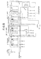
- Fig. 7 shows a concrete example of the RF signal transmitter circuit and Figs. 8 and 9 show concrete examples of the RF signal receiver, respectively.
- the RF signal transmitter shown in Fig. 7 comprises an oscillator circuit 34, an amplifier circuit 35, a one-shot circuit 36 and a voltage detector circuit 37 and is adapted to be driven by a source battery E1 having a source voltage + B (e.g., 3V).
- a frequency generated by a quartz oscillator 38 of the oscillator circuit 34 is amplified by the amplifier 35 and transmitted through the antenna 9.
- the oscillator portion 10 corresponds to a combination of the oscillator circuit 34 and the amplifier 35.
- the one-shot circuit 36 and the voltage detector 37 are new components and operations thereof will be described in detail later. Bases of a transister TR1 of the oscillator 34 and a transister TR2 of the amplifier 35 are connected to an output of the one-shot circuit 36.
- RF signal receivers shown in Figs. 8 and 9 are driven by battery E2 (Fig. 9) having source voltage + B (e.g. 3V), respectively.
- the receiver in Fig. 8 comprises a tuning circuit 41, a high frequency amplifier 60, a frequency onverter 42, an intermediate frequency (IF) amplifier 43, a filter 44 and a detector 45 and the receiver in Fig. 9 further includes the one-shot circuit 46 and the oscillator 49.
- An audible signal is generated by a piezo buzzer 50 provided in the oscillator 49.
- An antenna 11 is the same as that shown by 9 in Fig. 4.
- the level discriminator 15 in Fig. 4 corresponds to the one-shot circuit 46.
- the signal generator 5 and the loud speaker 6 in Fig. 4 correspond to the oscillator 49 and the piezo buzzer 50.
- a voltage detector 51 and an intermittent oscillator 47 are provided in each of the RF signal receiver, which will be described in detail later. Outputs of the one-shot circuit 46 and the intermittent oscillator 47 are connected to inputs of an AND gate 48 of the oscillator 49.
- the RF signal generator shown in Fig. 7 is mounted in the portable unit 31, as shown in Fig. 10.
- a push-button 32 in Fig. 10 is identical to that shown by the same reference neumeral in Fig. 7.
- Either of the RF signal generators shown in Figs. 8 and 9 is mounted on the position indicator unit 33, as shown in Fig. 11.
- the piezo buzzer 50 in Fig. 9 is arranged in a position P.
- the buzzer 50 of the position indicator unit 33 When a visually handicapped person carrying the portable unit 31 depresses the button 32, the buzzer 50 of the position indicator unit 33 generates sound to guide him to the place where the latter is disposed.
- the one-shot circuit 36 comprises a pair of OR gates OR1 and OR2, resistors R1, R2 and R3 and a capacitor C1.
- An output of the OR gate OR1 is connected to the aforementioned transisters TR1 and TR2, the resister R1 being connected to an output of an inverter IV1 of the voltage detector 37 through a diode D1.
- the inverter IV1 may be of CMOS type in which an inversion level is changed according to the level of the battery voltage + B. A fraction of the battery voltage + B obtained by series connected diodes D2 and D3 is applied to an input of the inverter IV1.
- each of the diodes D2 and D3 has a voltage characteristics of 0.6V in view of the battery voltage of 3V. That is, V ab is set to substantially 1.2V.
- constants of the respective circuit elements are selected such that a time for which the output of OR gate OR1 is in "H" level is about 1.5 seconds.
- the one-shot circuit 36 outputs "H" level and, therefore, the oscillator 34 and the amplifier 35 are energized to transmit a signal S1 through the antenna 9.
- the signal S1 is transmitted for about 1.5 seconds (Fig. 14).
- the intermittent oscillator 47 includes an OR gate OR3 and an inverter IV2.
- a voltage detector 51 is connected to one of inputs of the OR gate OR3, a voltage detector 51 is connected.
- the voltage detector 51 includes, as in the voltage detector 37 of the transmitter (Fig. 7), an inverter IV3 and diodes D4 and D5.
- the inverter IV3 is also of the type whose inversion level is varied according to the source voltage + B. Since the source voltage + B is about 3V, the diodes D4 and D5 are selected such that a voltage Vf across the diodes becomes about 1.2V.
- a pulse signal P1 shown by (a) in Fig. 13 appears at the output of the OR gate OR3 due to self-oscillation.
- a pulse width Ta depends on a capasitance of the capacitor C2 and a resistance of a resister R8, which is, in this embodiment, in the order of 0.15 seconds.
- a pulse width Tb depends, mainly on a capacitance of the capacitor C3 and a resistance of a resister R6, which is, in this embodiment, set to about 1 second.
- the pulse signal from the OR gate OR3 is fed to an AND gate 48 as a signal S4 and to bases of respective transisters of the frequency converter 42, the IF amplifier 43 and the detector 45 as a STB signal (strove signal), as shown in Fig. 8.
- the intermittent periodical driving of the receiver is to avoid a rapid consupmtion of the battery E2.
- the signal S1 transmitted from the transmitter (Fig. 7) is received by the antenna 11 of the receiver (Fig. 8), it is processed by the tuning circuit 41, the high frequency amplifier 60, the frequency converter 42, the IF amplifier 43, the filter 44 and the detector 45.
- the construction of the receiver mentioned above is the so-called super heterodyne receiver.
- the frequency converter 42 and other circuits operate in synchronism with the pulse signal P1 (Fig. 13a). Therefore, the signal S2 from the detector 45 takes in the form of narrow pulse as shown in Fig. 14.
- the output signal S2 incudes two pulses at most (Fig. 14) because the pulse width of the signal S1 is about 1.5 seconds and the pulse signal P1 (Fig. 13a) inputted as the STB signal has a period of about 1 second.
- the output signal S2 is then fed to the one-shot circuit 46 in Fig. 9 and inverted by the inverter IV4.
- the inverted signal is supplied to one of the inputs of the OR gate OR4.
- a pulse of the signal S2 is supplied to the OR gate OR4
- the point g a potential at which has been "H” is becomes "L” at that time, which is held for the same time. Therefore, the discharge time of the capacitor C3 of the intermittent oscillator 47 is shortened, resulting in the self-oscillation pulse period shortened, as shown in Fig.
- a switch 52 shown in Fig. 9 functions as a power switch as well as sound volume switch. That is, when it connects terminals 1 and 5, the power is turned off, terminals 2 and 6, sound level becomes low and terminals 4 and 8, the level becomes high.
- the signal S1 is transmitted through the antenna 9 (Fig. 7) when the switch 32 is closed.
- the signal S1 is received by the antenna 11 (Fig. 8) and the signal S2 is inputted to the one-shot circuit 46 (Fig. 9), as mentioned previously.
- the discharge current of the capacitor C1 of the one-shot circuit 36 flows through not the resister R1 but the resister R2.
- the discharge time of the capacitor C1 is longthened, so that the potential at an output point e of the OR gate OR1 is kept at "H" for a long time, say, about 5 seconds, as shown by a chain line in Fig. 12. Therefore, the signal S1 is transmitted from the antenna 9 for about 5 seconds as shown by a chain line in Fig. 14, which is received by the antenna 11.
- the signal S2 including pulses corresponding, in number, to the period of the signal S1 (about 5 seconds) is produced, which is supplied to the one-shot circuit 46 (Fig. 9).
- the output signal S3 of the OR gate OR4 of the one-shot circuit 46 is "H" for about 3 seconds in the normal state (Fig. 14).
- the signal S2 is supplied to the circuit 46 continuously even after the period of about 3 seconds lapses. Therefore, a second S3 signal is produced continuously to the first S3 signal, resulting in that the AND gate 48 is opened continuously for totally about 6 seconds. Therefore, the buzzer 50 is operated intermittently with a period of about 6 seconds, indicating the consumption of the battery E1.
- the position indicator unit When both of the batteries E1 and E2 of the portable unit 31 and the position indicator unit 33 are consummed, the position indicator unit produces the continuous sound with the period of about 6 seconds similarly.
Landscapes
- Health & Medical Sciences (AREA)
- General Health & Medical Sciences (AREA)
- Life Sciences & Earth Sciences (AREA)
- Animal Behavior & Ethology (AREA)
- Public Health (AREA)
- Veterinary Medicine (AREA)
- Engineering & Computer Science (AREA)
- Epidemiology (AREA)
- Pain & Pain Management (AREA)
- Physical Education & Sports Medicine (AREA)
- Rehabilitation Therapy (AREA)
- Physics & Mathematics (AREA)
- Ophthalmology & Optometry (AREA)
- Audiology, Speech & Language Pathology (AREA)
- Educational Administration (AREA)
- Educational Technology (AREA)
- General Physics & Mathematics (AREA)
- Theoretical Computer Science (AREA)
- Business, Economics & Management (AREA)
- Biomedical Technology (AREA)
- Heart & Thoracic Surgery (AREA)
- Vascular Medicine (AREA)
- Mobile Radio Communication Systems (AREA)
- Near-Field Transmission Systems (AREA)
- Audible And Visible Signals (AREA)
Description
- The present invention relates to a guide device having at least one portable unit being adapted to be carried by a person, a position indicator unit being adapted to be located at a position to which the person is to be guided, the portable unit including a battery voltage detector circuit, a signal oscillator, a circuit for transmitting the signal from said oscillator, the position indicator unit is including a circuit for receiving the signal transmitted by the protable unit, a loud speaker for producing sound in respnse to reception of said received signal, a loud speaker actuating circuit and source batteries included in said portable and said position indicator unit.
- A device of said nature, namely, for locating mislaid objects, e. g. spectacles or bunched of keys, is known from the AT-B-377367 said device including at least one transmitter and one receiving unit, the latter being in connection with the former via a wireless transmission link and connected to a signal transmitter; the receiver is attached to the object to be protected against loss. A major problem in such battery-powered transmitting and receiving units is the power supply, as the batteries have to be extremely small for design reasons, and their power is thus exhausted within a very short time. A transmitting unit with a receiver is therefore provided, which makes it possible to energize the transmitter only in case of need, i.e. when searching for an object, and to operate the receiver in pulsed-mode operation. This results in a considerably lower power consumption, and thus in longer battery life.
- For a visually handicapped person in a hotel room or in a train, it may be relatively easy to get closer to an aimed place by means of estimated course, distance thereto and atmosphere, etc. Even so, however, it may be difficult to get the aimed place exactly.
- An object of the present invention is to provide a guiding device capable of guiding a visually handicapped person to an aimed place exactly and of being used by him easily regardless of location of the aimed place.
- Another object of the present invention is to provide such device as mentioned above, which is capable of informing a consumption of battery used as a power source of the device.
- The above objects are achieved by a guide device according to
claims - The guide device for visually handicapped person according to the present invention, includes a portable unit and a position indicator unit. The portable unit includes a transmitting time control circuit with variable actuating time, adapted to change the time for transmitting the radio frequency signal when the battery voltage of the portable unit is lowered.
- The circuit for receiving the radio frequency signal in the position indicator unit transmitted by said portable unit, is adapted to change the time of signal reception when the lowering of the battery voltage in the portable unit has been detected the position indicator unit further includes a battery voltage detector circuit and a circuit for controlling the loud speaker actuating time, said circuit being adapted to change the loud spaker actuating time in response to a change of the actuating time of the radio frequencey receiving circuit and being further adapted to change, but in a different manner, the loud speaker actuating time when the battery voltage lowering of the position indicator unit has been detected.
- As mentioned previously, it is relatively easy for the visually handicapped person to get closer to the aimed place. When he gets closer to the place, the RF signal transmitted from the portable unit is received by the receiver of the position indicator unit disposed at the aimed place and an audio signal is generated by the loud speaker. He can get the aimed place exactly by means of the audio signal.
-
- Fig. 1 is a perspective view of an example of a portable unit;
- Fig. 2 is a block circuit diagram of an example of a RF signal transmitter;
- Fig. 3 is a perspective view of an example of a position indicator unit;
- Fig. 4 is a block circuit diagram of an exmaple of a RF signal receiver;
- Fig. 5 is a block circuit diagram of another example of the RF signal transmitter;
- Fig. 6 is a block circuit diagram of another example of the RF receiver;
- Fig. 7 is a circuit diagram of the RF signal transmitter;
- Figs. 8 and 9 are circuit diagrams of the RF signal receivers, respectively;
- Fig. 10 is a perspective view of another example of the portable unit;
- Fig. 11 is a perspective view of another example of the position indicator unit; and
- Figs. 12 to 15 show timing charts of operations of the circuits shown in Figs. 7 to 9, respectively.
- Fig. 1 shows a
portable unit 1. Theportable unit 1 includes aRF signal transmitter 2 composed of anantenna 9 and anoscillator 10 as shown in Fig. 2. TheRF signal transmitter 2 has an output power small enough to cover a distance as short as about 10 meters, for example. Such transmitter can be constituted with any conventional circuit and, due to its compactness, it is possible to make theportable unit 1 compact and light weight, which is desired since it has to be always carried by a visually handicapped person. - Fig. 3 shows a
position indicator unit 3 which includes aRF signal receiver 4, anaudio signal generator 5 and aloud speaker 6 as shown in Fig. 4. TheRF signal receiver 4 is composed of anantenna 11, adetector 13 and alevel discriminator 15. A RF signal transmitted by theRF signal transmitter 2 shown in Fig. 2 is selectively received by theRF signal receiver 4 and discriminated in level. When the level exceeds a predetermined reference level, theloud speaker 6 is driven by theaudio signal generator 5 to produce suitable sound. That is, theaudio signal generator 5 is a drive circuit responsive to an output of thelevel discriminator 15 for driving theloud speaker 6. Theposition indicator unit 3 is set or mounted at a place such as entrance of a building, public telephone, train seat, class room seat, etc., which is the place aimed by the visually handicapped person. It may be possible to mount such position indicator unit even on his white stick so that, when he drops it, he can pick it up easily. - Parts depicted by 7 in Fig. 1 and 8 in Fig. 3 are sets of switches. The
switch set 7 includes threeswitches set 8 includes threeswitches RF signal transmitter 2 or a receiving signal frequency of theRF receiver 4 between two values. A first one of the two frequency values is common for theportable units 1 and, if a suitable one of the switches of theswitch set 8 of theposition indicator unit 3 disposed at, for example, an entrance of a conference room has been depressed, all of the persons who carry the respectiveportable units 1 are informed by sound generated by theposition indicator unit 3 when they approach the conference room. - The other, second frequency value is common for specific one of the
portable units 1 and specific one of theposition indicator units 3, so that, when one of the switches of the switch set 7 of one of theportable units 1 and one of the switches of theswitch set 8 of theposition indicator unit 3 have been depressed to select the second frequency and when theportable unit 1 approaches theposition indicator unit 3, the latter generates sound. Theposition indicator unit 3 does not produce such sound when other portable units than the specific unit approach it. Such specific frequency is used only between the specific portable unit and the specific position indicator unit. - When a
position indicator unit 3 which is set to the first frequency is disposed at any public facility such as library, etc., any person who carry his ownportable unit 1 can be guided thereto by setting its frequency to the first frequency. - Although, in the above embodiment, each unit has selectable two frequencies for common use and private use, it is clear that a single frequency can be used to cover all of the units.
- Further, it is possible to provide in the RF signal transmitter 12 a
code modulator 16 as shown in Fig. 5 so that a specific code signal which may be defined by a specific frequency or amplitude and assigned to a differentportable unit 1 is generated. In such case, such specific code signal is received by theRF signal receiver 14 having a decoder/discriminator portion 17 as shown in Fig. 6. The effect of this modification is substantially the same as that described before. - Fig. 7 shows a concrete example of the RF signal transmitter circuit and Figs. 8 and 9 show concrete examples of the RF signal receiver, respectively.
- The RF signal transmitter shown in Fig. 7 comprises an
oscillator circuit 34, anamplifier circuit 35, a one-shot circuit 36 and avoltage detector circuit 37 and is adapted to be driven by a source battery E1 having a source voltage + B (e.g., 3V). A frequency generated by aquartz oscillator 38 of theoscillator circuit 34 is amplified by theamplifier 35 and transmitted through theantenna 9. Theoscillator portion 10 corresponds to a combination of theoscillator circuit 34 and theamplifier 35. The one-shot circuit 36 and thevoltage detector 37 are new components and operations thereof will be described in detail later. Bases of a transister TR1 of theoscillator 34 and a transister TR2 of theamplifier 35 are connected to an output of the one-shot circuit 36. - RF signal receivers shown in Figs. 8 and 9 are driven by battery E2 (Fig. 9) having source voltage + B (e.g. 3V), respectively. The receiver in Fig. 8 comprises a
tuning circuit 41, ahigh frequency amplifier 60, afrequency onverter 42, an intermediate frequency (IF)amplifier 43, afilter 44 and adetector 45 and the receiver in Fig. 9 further includes the one-shot circuit 46 and theoscillator 49. An audible signal is generated by apiezo buzzer 50 provided in theoscillator 49. Anantenna 11 is the same as that shown by 9 in Fig. 4. Thedetector portion 13 in Fig. 4 corresponds to a combination of thetuning circuit 41, thehigh frequency amplifier 60, thefrequency converter 42, theIF amplifier 43, thefilter 44 and thedetector 45. Thelevel discriminator 15 in Fig. 4 corresponds to the one-shot circuit 46. Thesignal generator 5 and theloud speaker 6 in Fig. 4 correspond to theoscillator 49 and thepiezo buzzer 50. - As shown in Fig. 9, a
voltage detector 51 and anintermittent oscillator 47 are provided in each of the RF signal receiver, which will be described in detail later. Outputs of the one-shot circuit 46 and theintermittent oscillator 47 are connected to inputs of an ANDgate 48 of theoscillator 49. - The RF signal generator shown in Fig. 7 is mounted in the
portable unit 31, as shown in Fig. 10. A push-button 32 in Fig. 10 is identical to that shown by the same reference neumeral in Fig. 7. - Either of the RF signal generators shown in Figs. 8 and 9 is mounted on the
position indicator unit 33, as shown in Fig. 11. thepiezo buzzer 50 in Fig. 9 is arranged in a position P. - When a visually handicapped person carrying the
portable unit 31 depresses thebutton 32, thebuzzer 50 of theposition indicator unit 33 generates sound to guide him to the place where the latter is disposed. - In a case when either or both of the batteries E1 (Fig. 7) of the
portable unit 31 and E2 (Fig. 9) of theposition indicator unit 33 are discharged to a level at or under which the signal transmission and/or receiving becomes impossible, it is detected by an operation of the combined one-shot circuit 36 and thevoltage detector 37 in Fig. 7 or the combinedvoltage detector 51 and theintermittent oscillator 47 in Fig. 9. - In Fig. 7, the one-
shot circuit 36 comprises a pair of OR gates OR1 and OR2, resistors R1, R2 and R3 and a capacitor C1. An output of the OR gate OR1 is connected to the aforementioned transisters TR1 and TR2, the resister R1 being connected to an output of an inverter IV1 of thevoltage detector 37 through a diode D1. The inverter IV1 may be of CMOS type in which an inversion level is changed according to the level of the battery voltage + B. A fraction of the battery voltage + B obtained by series connected diodes D2 and D3 is applied to an input of the inverter IV1. Since a diode has a general tendency of holding a substantially constant voltage across it terminals regardless of current flowing therethrough, a voltage Vab between points a and b is maintained at a substantially constant value. In this embodiment, each of the diodes D2 and D3 has a voltage characteristics of 0.6V in view of the battery voltage of 3V. That is, Vab is set to substantially 1.2V. - When the battery E1 is maintained 3V, the output of the inverter IV1 is in "L" state.
- In this normal state, when the
switch 32 is depressed to turn it on, a "L" level is applied temporarily (time being variable by a time for which theswitch 32 is depressed) to one (C) of the terminals of the OR gate OR1, by which the capacitor C1 is charged and then discharged through the resisters R1 and R2 because the output of the inverter IV1 is in "L" level. The output levels of the OR gates OR1 and OR2 are kept in "H" and "L" states, respectively, during the terminal voltage of the capacitor C1 is higher than the inversion level Vr of the OR gate OR2. - In this embodiment, constants of the respective circuit elements are selected such that a time for which the output of OR gate OR1 is in "H" level is about 1.5 seconds. For the latter time, the one-
shot circuit 36 outputs "H" level and, therefore, theoscillator 34 and theamplifier 35 are energized to transmit a signal S1 through theantenna 9. Thus, the signal S1 is transmitted for about 1.5 seconds (Fig. 14). - In Fig. 9, the
intermittent oscillator 47 includes an OR gate OR3 and an inverter IV2. To one of inputs of the OR gate OR3, avoltage detector 51 is connected. Thevoltage detector 51 includes, as in thevoltage detector 37 of the transmitter (Fig. 7), an inverter IV3 and diodes D4 and D5. The inverter IV3 is also of the type whose inversion level is varied according to the source voltage + B. Since the source voltage + B is about 3V, the diodes D4 and D5 are selected such that a voltage Vf across the diodes becomes about 1.2V. - When the voltage + B of the battery E2 is normal and kept at about 3V, an output level of the inverter IV3 is "H".
- In this normal condition, when a receiving signal S2 is not input to the one-
shot circuit 46, i.e., the antenna 11 (Fig. 8) is not receiving a receiving signal S1, a level at an output g of the inverter IV5 is "H". In such condition, a pulse signal P1 shown by (a) in Fig. 13 appears at the output of the OR gate OR3 due to self-oscillation. In this case, a pulse width Ta depends on a capasitance of the capacitor C2 and a resistance of a resister R8, which is, in this embodiment, in the order of 0.15 seconds. Further, a pulse width Tb depends, mainly on a capacitance of the capacitor C3 and a resistance of a resister R6, which is, in this embodiment, set to about 1 second. - The pulse signal from the OR gate OR3 is fed to an AND
gate 48 as a signal S4 and to bases of respective transisters of thefrequency converter 42, theIF amplifier 43 and thedetector 45 as a STB signal (strove signal), as shown in Fig. 8. - Since there is no signal S2 inputted to the one-
shot circuit 46, the output level of the latter to the ANDgate 48 is "L" and theoscillator 49 does not oscillate. Therefore, thebuzzer 50 of theoscillator 49 does not produce sound even if an intermittent pulse P1 (S4) from theintermittent oscillator 47 is supplied to the ANDgate 48. - When the intermittent pulse signal P1 is fed to the respective circuits of the receiver (Fig. 8) as the STB signal, these circuits operate for a rising time of the pulse, i.e., Ta = 0.15 seconds. The intermittent periodical driving of the receiver is to avoid a rapid consupmtion of the battery E2.
- When the signal S1 transmitted from the transmitter (Fig. 7) is received by the
antenna 11 of the receiver (Fig. 8), it is processed by thetuning circuit 41, thehigh frequency amplifier 60, thefrequency converter 42, theIF amplifier 43, thefilter 44 and thedetector 45. The construction of the receiver mentioned above is the so-called super heterodyne receiver. In this case, thefrequency converter 42 and other circuits operate in synchronism with the pulse signal P1 (Fig. 13a). Therefore, the signal S2 from thedetector 45 takes in the form of narrow pulse as shown in Fig. 14. In this embodiment, the output signal S2 incudes two pulses at most (Fig. 14) because the pulse width of the signal S1 is about 1.5 seconds and the pulse signal P1 (Fig. 13a) inputted as the STB signal has a period of about 1 second. - The output signal S2 is then fed to the one-
shot circuit 46 in Fig. 9 and inverted by the inverter IV4. The inverted signal is supplied to one of the inputs of the OR gate OR4. When a pulse of the signal S2 is supplied to the OR gate OR4, a signal S3 which is in "H" state for a time determined by a time constant of a capacitor C4 and a resister R7 , say, 3 seconds, is obtained at a point h. The point g a potential at which has been "H" is becomes "L" at that time, which is held for the same time. Therefore, the discharge time of the capacitor C3 of theintermittent oscillator 47 is shortened, resulting in the self-oscillation pulse period shortened, as shown in Fig. 13b. In this embodiment, it is shortened from about 1 second to about 0.3 seconds. Therefore, during the signal S3 is provided by the one-short circuit 46, a pulse signal P2 having shorter period is applied to the other input of the ANDgate 48, as shown in Fig. 14. As a result, thebuzzer 50 produces an intermittent sound of periodicity of about 0.45 seconds for about 3 seconds, which is used to guide a visually handicapped person. - A
switch 52 shown in Fig. 9 functions as a power switch as well as sound volume switch. That is, when it connectsterminals terminals terminals - The operation of the
portable unit 31 and theposition indicator 33 in normal use has been described. - Now, a case where the battery E1 (Fig. 7) of the
portable unit 31 or the battery E2 (Fig 9) of theposition indicator unit 33 is discharged will be described. - Since the
portable unit 31 is normal, the signal S1 is transmitted through the antenna 9 (Fig. 7) when theswitch 32 is closed. The signal S1 is received by the antenna 11 (Fig. 8) and the signal S2 is inputted to the one-shot circuit 46 (Fig. 9), as mentioned previously. - In Fig. 9, with the battery E2 consumed, the voltage level applied to the inverter IV3 is lowered. As mentioned previously, the inversion level of the inverter IV3 is changed by change of the applied voltage. Assuming that the voltage level is lowered from 3V to 2V, the inversion level is lowered from 1.5V to 1V. In this case, the input voltage Vf is always kept at the constant value, say, 1.2V, by the diodes D4 and D5 regardless of the inversion level change. Therefore, the output of the inverter IV3 is changed fronl "H" in the normal state to "L" and, thus, the OR gate OR3 provides its output "H" which is supplied to the AND
gate 48 as a signal S4 (Fig. 15). As a result, thebuzzer 50 produces sound continuously for a time during which an OR gate OR4 of the one-shot circuit 46 is "H", i.e., about 3 seconds, indicating a consumption of the battery E2 of theposition indication unit 33. - When the battery E1 of the
portable unit 31 is consummed, the voltage applied to the inverter IV1 of thevoltage detector 37 in Fig. 7 is lowered, upon which the output of the inverter IV1 is changed from "L" to "H" as for the same reason for the voltage detector 51 (Fig. 9). - With the output "H" of the inverter IV1, the discharge current of the capacitor C1 of the one-
shot circuit 36 flows through not the resister R1 but the resister R2. As a result, the discharge time of the capacitor C1 is longthened, so that the potential at an output point e of the OR gate OR1 is kept at "H" for a long time, say, about 5 seconds, as shown by a chain line in Fig. 12. Therefore, the signal S1 is transmitted from theantenna 9 for about 5 seconds as shown by a chain line in Fig. 14, which is received by theantenna 11. - In the receiver (Fig. 8), the signal S2 including pulses corresponding, in number, to the period of the signal S1 (about 5 seconds) is produced, which is supplied to the one-shot circuit 46 (Fig. 9).
- The output signal S3 of the OR gate OR4 of the one-
shot circuit 46 is "H" for about 3 seconds in the normal state (Fig. 14). However, when the battery E1 as consummed, the signal S2 is supplied to thecircuit 46 continuously even after the period of about 3 seconds lapses. Therefore, a second S3 signal is produced continuously to the first S3 signal, resulting in that the ANDgate 48 is opened continuously for totally about 6 seconds. Therefore, thebuzzer 50 is operated intermittently with a period of about 6 seconds, indicating the consumption of the battery E1. - When both of the batteries E1 and E2 of the
portable unit 31 and theposition indicator unit 33 are consummed, the position indicator unit produces the continuous sound with the period of about 6 seconds similarly.
Claims (2)
- A guide device having at least one portable unit (1, 31) being adapted to be carried by a person, a position indicator unit (3, 33) being adapted to be located at a position to which the person is to be guided, the portable unit including a battery voltage detector circuit (37), a signal oscillator (10, 34) a circuit for transmitting the signal from said oscillator (9, 45), the position indicator unit is including a circuit for receiving the signal transmitted by the portable unit (1, 31) a loud speaker (6) for producing sound in response to reception of said received signal, a loud speaker actuating circuit (49) and source batteries (E1, E2) included in said portable and said position indicator unit,
characterised in that,
the signal oscillator of the portable unit (1, 31) is a radio frequency signal oscillator;
in that the portable unit further includes a tranmitting time control circuit (36) with variable actuating time, adapted to change the time for transmitting the radio frequency signal (2, 3, 35) when the battery voltage of the portable unit is lowered;
in that the circuit for receiving the radio frequency signal (11, 41 to 45, 60) in the position indicator unit (3, 33) transmitted by said portable unit, is adapted to change the time of signal reception when the lowering of the battery voltage in the portable unit has been detected;
and in that the position indicator unit (3, 33) further includes a battery voltage detector circuit (37) and a circuit for controlling the loud speaker actuating time, said circuit being adapted to change the loud speaker actuating time in response to a change of the actuating time of the radio frequency receiving circuit and being further adapted to change, but in a different manner, the loud speaker actuating time when the battery voltage lowering of the position indicator unit has been detected. - The guide device as claimed in claim 1,
wherein each of said portable unit (1, 31) and said position indicator unit (3, 33) includes a source battery (E1, E2), said loud speaker (6) is adapted to generate an intermittent sound when a battery voltage of said battery of said portable unit is high enough, and when said battery is consumed, the time for which said radio frequency signal is transmitted by said radio frequency signal oscillator is elongated and the time for which sound is generated by said loud speaker of said position indicator unit is also elongated correspondingly, so that said loud speaker generated a continuous sound.
Applications Claiming Priority (4)
| Application Number | Priority Date | Filing Date | Title |
|---|---|---|---|
| JP812088U JPH01115344U (en) | 1988-01-27 | 1988-01-27 | |
| JP8120/88U | 1988-01-27 | ||
| JP136136/88U | 1988-10-20 | ||
| JP1988136136U JPH0523001Y2 (en) | 1988-10-20 | 1988-10-20 |
Publications (2)
| Publication Number | Publication Date |
|---|---|
| EP0326129A1 EP0326129A1 (en) | 1989-08-02 |
| EP0326129B1 true EP0326129B1 (en) | 1992-12-02 |
Family
ID=26342567
Family Applications (1)
| Application Number | Title | Priority Date | Filing Date |
|---|---|---|---|
| EP89101343A Expired EP0326129B1 (en) | 1988-01-27 | 1989-01-26 | Guiding device for visually handicapped person |
Country Status (4)
| Country | Link |
|---|---|
| US (1) | US5032836A (en) |
| EP (1) | EP0326129B1 (en) |
| DE (1) | DE68903644T2 (en) |
| ES (1) | ES2035962T3 (en) |
Families Citing this family (34)
| Publication number | Priority date | Publication date | Assignee | Title |
|---|---|---|---|---|
| IT8820267A0 (en) * | 1988-04-20 | 1988-04-20 | Loredana Repucci Ales | RADIO TRANSMISSION SYSTEM OF INFORMATION, MANAGED BY A COMPUTER, DESIGNED TO HELP BLIND PEOPLE IN COMVING IN THE CITY. |
| JPH02257185A (en) * | 1989-03-30 | 1990-10-17 | Canon Inc | Image information processor |
| EP0423042A1 (en) * | 1989-10-10 | 1991-04-17 | Sociedad Publica Eusko Trenbideak/Ferrocarriles Vascos, S.A. ( Et/Fv, S.A.) | Improved transportation vehicle |
| FR2661607A1 (en) * | 1990-05-04 | 1991-11-08 | Fradin Boris | Installation for guiding individuals, such as the partially sighted, in an urban environment |
| ES2038886B1 (en) * | 1991-04-15 | 1994-08-01 | Pastor Vicente Miguel Segui | WARNING INSTALLATION FOR INVIDENTS OF THE LIGHT SIGNALS EMITTED BY A TRAFFIC LIGHT. |
| ES2068049B1 (en) * | 1991-06-13 | 1996-07-01 | Ciberveu Sa | GUIDANCE ASSISTANCE SYSTEM FOR INVIDENTS. |
| AU7374294A (en) * | 1993-07-28 | 1995-02-28 | Board Of Regents, The University Of Texas System | Remotely controlled, infrared beacon system for guiding the visually impaired |
| ES2087014B1 (en) * | 1993-10-27 | 1998-09-01 | Garcia Ramon Manrique | OBSTACLE DETECTOR-NOTICE DEVICE. |
| SE504327C2 (en) * | 1994-03-02 | 1997-01-13 | Transistor Ab | Modularly constructed, portable system for hearing or visually handicapped persons |
| US5470233A (en) * | 1994-03-17 | 1995-11-28 | Arkenstone, Inc. | System and method for tracking a pedestrian |
| AU6692194A (en) * | 1994-04-11 | 1995-10-30 | Nauchno-Vnedrencheskoe Predpriyatie "Reabilitatsya" | Guide device for the blind |
| US5680102A (en) * | 1994-07-29 | 1997-10-21 | Dimango Products | RF data communication link for wireless audible indication system |
| US5508699A (en) * | 1994-10-25 | 1996-04-16 | Silverman; Hildy S. | Identifier/locator device for visually impaired |
| DK171780B1 (en) * | 1995-09-05 | 1997-05-20 | Dansk Service Center | Visual and / or acoustic auxiliary equipment for personal use, as well as applications of the same. |
| US5616901A (en) * | 1995-12-19 | 1997-04-01 | Talking Signs, Inc. | Accessible automatic teller machines for sight-impaired persons and print-disabled persons |
| KR100208772B1 (en) * | 1996-01-17 | 1999-07-15 | 서정욱 | Interactive system for guiding the blind and its control method |
| US5790050A (en) * | 1996-06-25 | 1998-08-04 | Parker; Peter | Method and apparatus for a signal translator |
| US5806017A (en) * | 1996-08-19 | 1998-09-08 | Board Of Regents The University Of Texas System | Electronic autorouting navigation system for visually impaired persons |
| US5803740A (en) * | 1997-04-22 | 1998-09-08 | Board Of Trustees Of Western Michigan University | Learning and assessment aid for a severely visually impaired individual |
| US6469956B1 (en) | 1999-03-29 | 2002-10-22 | Xing Zeng | Ultrasonic distance detection for visually impaired pedestrians |
| US6502032B1 (en) | 2001-06-25 | 2002-12-31 | The United States Of America As Represented By The Secretary Of The Air Force | GPS urban navigation system for the blind |
| US6977579B2 (en) * | 2003-11-06 | 2005-12-20 | International Business Machines Corporation | Radio frequency identification aiding the visually impaired |
| US7039522B2 (en) * | 2003-11-12 | 2006-05-02 | Steven Landau | System for guiding visually impaired pedestrian using auditory cues |
| US7075289B2 (en) * | 2004-07-27 | 2006-07-11 | Der Ee Electrical Instrument Co., Ltd. | Wireless remote control measuring multipurpose meter |
| US20080224894A1 (en) * | 2005-04-18 | 2008-09-18 | Hyun Duk Uhm | System of Guidance of the Road |
| DE102008005164B4 (en) * | 2008-01-19 | 2014-03-27 | Arkadij Gershman | Method for non-contact object identification and determination of the direction to this object and receiver and transmitter and receiver system therefor |
| US9201143B2 (en) | 2009-08-29 | 2015-12-01 | Echo-Sense Inc. | Assisted guidance navigation |
| US9615147B2 (en) | 2010-05-17 | 2017-04-04 | Flir Systems, Inc. | Multisensory meter system |
| WO2012068280A1 (en) | 2010-11-16 | 2012-05-24 | Echo-Sense Inc. | Remote guidance system |
| FR2977874B1 (en) * | 2011-07-13 | 2014-01-10 | Plastic Omnium Cie | WASTE COLLECTION CONTAINER HAVING A MALVOYING ASSISTANCE DEVICE AND INSTALLATION COMPRISING AT LEAST ONE SUCH CONTAINER |
| CN102688120B (en) * | 2012-06-08 | 2014-07-16 | 綦峰 | Colored audio and video guide method and colored audio and video guide device |
| FR3017304B1 (en) * | 2014-02-11 | 2017-07-14 | X'sin | VIBRATING BRACELET |
| EP3047825A1 (en) * | 2015-01-23 | 2016-07-27 | ADI Access Limited | Directional guidance apparatus |
| US20190227002A1 (en) * | 2018-01-24 | 2019-07-25 | Corning Incorporated | Apparatus and methods for inspecting damage intensity |
Family Cites Families (16)
| Publication number | Priority date | Publication date | Assignee | Title |
|---|---|---|---|---|
| US3225265A (en) * | 1961-09-08 | 1965-12-21 | K & M Electronics Company | Remote control electrical switch and radio frequency actuating system therefor |
| US3321737A (en) * | 1965-02-03 | 1967-05-23 | Russell Lindsay | Sonar-type sensory aids |
| US3550105A (en) * | 1967-08-08 | 1970-12-22 | Warwick Electronics Inc | Battery condition indicator |
| US3795896A (en) * | 1972-04-26 | 1974-03-05 | Avant Guard Devices Inc | Wireless alarm system |
| FR2382886A1 (en) * | 1977-03-11 | 1978-10-06 | Cochart Emmanuel | Blind person guiding system - uses detector on each foot or bicycle to receive audible signal from buried metal strip |
| US4191948A (en) * | 1978-10-23 | 1980-03-04 | Napco Security System Inc. | Digital transmission apparatus particularly adapted for security systems |
| US4232308A (en) * | 1979-06-21 | 1980-11-04 | The Scott & Fetzer Company | Wireless alarm system |
| DE2946721A1 (en) * | 1979-11-20 | 1981-05-27 | Reinhold 4000 Düsseldorf Goldmann | Orientation system for blind persons - uses constant or interrupted sound emitted from small case hung at strategic point in area such as garden, room etc. |
| GB2074816A (en) * | 1980-02-01 | 1981-11-04 | Techwise International Ltd | A door bell or like device arranged to emit a warning sound upon activation of a remotely situated switch |
| DE3046895C2 (en) * | 1980-12-12 | 1982-09-23 | Gerald 8021 Taufkirchen Kampel | Avalanche search device, especially for use in searching for avalanche victims |
| AT377367B (en) * | 1982-04-20 | 1985-03-11 | Badura Skoda Paul | DEVICE FOR DETECTING LOST OBJECTS |
| DE3215942A1 (en) * | 1982-04-29 | 1983-11-03 | Franz 7963 Altshausen Fuchshuber | Monitoring device |
| GB2137387B (en) * | 1983-03-25 | 1986-09-17 | Graham David Francis Sharp | A remotely activatable alarm system |
| DE3616186A1 (en) * | 1986-05-14 | 1987-11-19 | Dietmar Dipl Ing Rosenke | Guiding system for the blind |
| JPS63172985A (en) * | 1987-01-12 | 1988-07-16 | Katsuhiko Hiramatsu | Detecting method for lost article and thing left behind |
| US4804943A (en) * | 1987-07-02 | 1989-02-14 | Isaac Soleimani | Remotely controlled briefcase alarm |
-
1989
- 1989-01-26 DE DE8989101343T patent/DE68903644T2/en not_active Expired - Fee Related
- 1989-01-26 EP EP89101343A patent/EP0326129B1/en not_active Expired
- 1989-01-26 ES ES198989101343T patent/ES2035962T3/en not_active Expired - Lifetime
-
1990
- 1990-06-18 US US07/541,180 patent/US5032836A/en not_active Expired - Lifetime
Also Published As
| Publication number | Publication date |
|---|---|
| DE68903644T2 (en) | 1993-04-08 |
| US5032836A (en) | 1991-07-16 |
| EP0326129A1 (en) | 1989-08-02 |
| ES2035962T3 (en) | 1993-05-01 |
| DE68903644D1 (en) | 1993-01-14 |
Similar Documents
| Publication | Publication Date | Title |
|---|---|---|
| US5032836A (en) | Guiding device for visually handicapped person | |
| US5633742A (en) | Optical data communication and location apparatus, system and method and transmitters and receivers for use therewith | |
| EP1006959B1 (en) | A portable modular alarm system | |
| KR100670439B1 (en) | Automatic time-setting system for portable units with clock | |
| EP0073681A2 (en) | Improvements relating to position detection devices | |
| US4523193A (en) | Remote-controlled doorbell signal receiver | |
| US4337529A (en) | Pace timing device | |
| CN108407569A (en) | Control method, system, computer equipment and the mounted air conditioner system of on-board air conditioner | |
| US4101873A (en) | Device to locate commonly misplaced objects | |
| US5666331A (en) | Alarm clock | |
| US4110741A (en) | Device for monitoring physical activity of persons | |
| EP0358478A2 (en) | Multi-channel remote control transmitter | |
| US3383682A (en) | Radar glasses for the blind | |
| US4242745A (en) | Electronic timepiece with electroacoustic transducer | |
| US5528230A (en) | Remote control transmitter/receiver system | |
| US7173881B1 (en) | Silent morning alarm | |
| IE45864B1 (en) | A sound generator | |
| EP1501059B1 (en) | Remote doorbell chime extender | |
| US6577559B1 (en) | Electronic converter for converting an acoustic signal into a pseudo-digital signal, timepiece including such a converter and two-directional communication method via acoustic waves | |
| ATE156557T1 (en) | DOOR MONITORING DEVICE | |
| JP2801868B2 (en) | Wireless guidance device | |
| Debnath et al. | An electronically guided walking stick for the blind | |
| NZ233206A (en) | Detecting peak value in flywheel circuit | |
| US6527696B1 (en) | Wave generation apparatus | |
| GB2428527A (en) | Portable heart-rate monitor system |
Legal Events
| Date | Code | Title | Description |
|---|---|---|---|
| PUAI | Public reference made under article 153(3) epc to a published international application that has entered the european phase |
Free format text: ORIGINAL CODE: 0009012 |
|
| 17P | Request for examination filed |
Effective date: 19890126 |
|
| AK | Designated contracting states |
Kind code of ref document: A1 Designated state(s): DE ES FR GB NL SE |
|
| 17Q | First examination report despatched |
Effective date: 19901115 |
|
| GRAA | (expected) grant |
Free format text: ORIGINAL CODE: 0009210 |
|
| AK | Designated contracting states |
Kind code of ref document: B1 Designated state(s): DE ES FR GB NL SE |
|
| PGFP | Annual fee paid to national office [announced via postgrant information from national office to epo] |
Ref country code: SE Payment date: 19921215 Year of fee payment: 5 |
|
| PGFP | Annual fee paid to national office [announced via postgrant information from national office to epo] |
Ref country code: FR Payment date: 19921221 Year of fee payment: 5 |
|
| PGFP | Annual fee paid to national office [announced via postgrant information from national office to epo] |
Ref country code: GB Payment date: 19930106 Year of fee payment: 5 |
|
| PGFP | Annual fee paid to national office [announced via postgrant information from national office to epo] |
Ref country code: ES Payment date: 19930112 Year of fee payment: 5 |
|
| REF | Corresponds to: |
Ref document number: 68903644 Country of ref document: DE Date of ref document: 19930114 |
|
| ET | Fr: translation filed | ||
| PGFP | Annual fee paid to national office [announced via postgrant information from national office to epo] |
Ref country code: NL Payment date: 19930131 Year of fee payment: 5 |
|
| PGFP | Annual fee paid to national office [announced via postgrant information from national office to epo] |
Ref country code: DE Payment date: 19930226 Year of fee payment: 5 |
|
| REG | Reference to a national code |
Ref country code: ES Ref legal event code: FG2A Ref document number: 2035962 Country of ref document: ES Kind code of ref document: T3 |
|
| PLBE | No opposition filed within time limit |
Free format text: ORIGINAL CODE: 0009261 |
|
| STAA | Information on the status of an ep patent application or granted ep patent |
Free format text: STATUS: NO OPPOSITION FILED WITHIN TIME LIMIT |
|
| 26N | No opposition filed | ||
| PG25 | Lapsed in a contracting state [announced via postgrant information from national office to epo] |
Ref country code: GB Effective date: 19940126 |
|
| PG25 | Lapsed in a contracting state [announced via postgrant information from national office to epo] |
Ref country code: SE Effective date: 19940127 Ref country code: ES Free format text: LAPSE BECAUSE OF NON-PAYMENT OF DUE FEES Effective date: 19940127 |
|
| PG25 | Lapsed in a contracting state [announced via postgrant information from national office to epo] |
Ref country code: NL Effective date: 19940801 |
|
| NLV4 | Nl: lapsed or anulled due to non-payment of the annual fee | ||
| GBPC | Gb: european patent ceased through non-payment of renewal fee |
Effective date: 19940126 |
|
| PG25 | Lapsed in a contracting state [announced via postgrant information from national office to epo] |
Ref country code: FR Effective date: 19940930 |
|
| PG25 | Lapsed in a contracting state [announced via postgrant information from national office to epo] |
Ref country code: DE Effective date: 19941001 |
|
| REG | Reference to a national code |
Ref country code: FR Ref legal event code: ST |
|
| EUG | Se: european patent has lapsed |
Ref document number: 89101343.5 Effective date: 19940810 |
|
| REG | Reference to a national code |
Ref country code: ES Ref legal event code: FD2A Effective date: 19990201 |