EP0326104A2 - Channel changing system - Google Patents
Channel changing system Download PDFInfo
- Publication number
- EP0326104A2 EP0326104A2 EP89101271A EP89101271A EP0326104A2 EP 0326104 A2 EP0326104 A2 EP 0326104A2 EP 89101271 A EP89101271 A EP 89101271A EP 89101271 A EP89101271 A EP 89101271A EP 0326104 A2 EP0326104 A2 EP 0326104A2
- Authority
- EP
- European Patent Office
- Prior art keywords
- radio
- station
- base station
- base stations
- line
- Prior art date
- Legal status (The legal status is an assumption and is not a legal conclusion. Google has not performed a legal analysis and makes no representation as to the accuracy of the status listed.)
- Granted
Links
Images


Classifications
-
- H—ELECTRICITY
- H04—ELECTRIC COMMUNICATION TECHNIQUE
- H04W—WIRELESS COMMUNICATION NETWORKS
- H04W36/00—Hand-off or reselection arrangements
- H04W36/0005—Control or signalling for completing the hand-off
- H04W36/0055—Transmission or use of information for re-establishing the radio link
- H04W36/0058—Transmission of hand-off measurement information, e.g. measurement reports
-
- H—ELECTRICITY
- H04—ELECTRIC COMMUNICATION TECHNIQUE
- H04W—WIRELESS COMMUNICATION NETWORKS
- H04W84/00—Network topologies
- H04W84/02—Hierarchically pre-organised networks, e.g. paging networks, cellular networks, WLAN [Wireless Local Area Network] or WLL [Wireless Local Loop]
- H04W84/10—Small scale networks; Flat hierarchical networks
- H04W84/16—WPBX [Wireless Private Branch Exchange]
Definitions
- the present invention relates to a channel changing system to be made depending on transfer of a mobile unit in the busy condition to the adjacent radio zone in such a mobile unit communication system as forming the one communication network with multiple radio zones.
- a mobile unit communication system has a configuration wherein radio base stations BS1 BSn are arranged in a plurality of radio zones #1 ⁇ #n, causing movable stations MS scattering therein to be capable of radio communication with such radio base stations BS1 ⁇ BSn and with regular telephone subscribers through the one or a few center stations 100 accommodating radio base stations BS1 ⁇ BSn.
- Fig. 2 illustrates a diagram for explaining the busy channel changing system through the frequency changing. That is, if a movable station MS having existed in the radio zone #(n-1) moves, for example, under the busy condition, to an adjacent radio zone #n, the radio zone #(n-1) is requested to change the radio frequency fa assigned to the radio base station BS(n-1) to the radio frequency fb assigned for the use to the radio base station BSn in the radio zone #n after the movement.
- this frequency changing system provides less frequency interference between respective radio zones and can therefore be said to be a system easily assuring management. Accordingly, the system described here is suitable, for example, to a large capacity and wide range system such as an automobile telephone system linking a plurality of zones.
- the mobile unit communication system described above makes communication channel changing, if the mobile unit transfers to an adjacent radio zone, at the region wherein the receiving electric field between the movable stations in the boundary of radio zones is low strictlyered. Therefore a protection circuit or control circuit is complicated and becomes expensive. Accordingly, such channel changing is controlled, for example, by a particular exchange control apparatus such as an automobile telephone exchanger. Such system is suitable to a large capacity and wide range system but to a regional small scale mobile unit communication system to which the applicable region is restricted because an expensive exchange control apparatus is required.
- the present invention is a channel changing system of a mobile unit communication system comprising a plurality of radio base stations making communication with movable stations through a radio channel and a control center station which accommodates such radio base stations for connecting them with a public telephone network.
- the center station is configurated comprising a private branch exchange accommodating the public telephone network and the lines extending from a plurality of radio base stations and a control apparatus which monitors signal receiving condition to make communication channel changing control.
- the control apparatus detects, based on the signal receiving condition, that a movable station moves to a radio zone of the adjacent base staton from a radio zone of a certain base station and issues a channel changing command, while the private branch exchanger changes the line by transfser of extension to the line of the adjacent base station from the line to the certain base station dependin on the movement of a movable station.
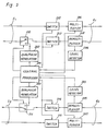
- Fig. 3 illustrates a mobile unit communication system utilizing a channel changing system in mobile unit communication as an embodiment of the present invention.
- 31 ⁇ 3 n designate radio base stations.
- the base stations 31 ⁇ 3 n respectively have their own radio zones #1 ⁇ #n, forming a communication service area.
- m radio frequencies (radio channels) from f1 ⁇ f m are used for the movable station 7 and radio base stations 31 ⁇ 3 n in this communication service area and the movable station 7 is capable of making radio communication with the radio base station using only one frequency among the radio frequencies f1 ⁇ f m .
- the sending and receiving frequency can be selected by changing, with a frequency synthesizer, the local oscillation frequency signal for converting the radio frequency (800 MHz, for example) and the intermediate frequency(455 kHz, for example).
- Each radio base station 31 ⁇ 3 n makes communication with a movable station using a channel among the radio frequencies f1 ⁇ f m .
- the movable station 7 uses the radio frequency f1 for communication with the base station 31, the other radio base stations 32 ⁇ 3 n in the same service area cannot use the radio frequency f1 for communication with the other movable station.
- the radio base stations 31 ⁇ 3 n In addition to the radio communication with a movable station using a certain radio frequency, the radio base stations 31 ⁇ 3 n also monitors radio communication using the other radio frequencies and thereby sends a call termination level signal to a connection controller 2 by supervising the termination level of all radio frequencies.
- the private branch exchanger 1 and connection controller 2 configurate a center station.
- the radio base station lines 41 ⁇ 4 n extending from the radio base stations 31 ⁇ 3 n are accommodated within the private branch exchanger 1 via the exchanger lines 51 ⁇ 5 n .
- the private branch exchanger 1 is then extended to a public telephone network 5.
- Fig. 4 illustrates a structure of the private branch exchanger.
- a switching circuit 11 is connected to the public telephone network 6 via a main wire interface 12 and also connected to the exchanger lines 51 ⁇ 5 n via an extension interface 13.
- a central processor 14 processes various control signals for the main wire and extension via respective interfaces and issues an instruction to the switching circuit for connection with the main wire or extension wire.
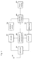
- Fig. 5 illustrates detail block diagram of the connection controller 2.
- 201 designates central processor, while 202 and 203 designate dial pulse generator, 204 and 205 designate level detector, 206 and 207 designate multiplex circuit, 208 and 209 designate separation circuit, 210 ⁇ 215 designate switch.
- the connection controller 2 provides the circuits for similar functions as is illustrated as much as the channels used of respective base stations among the stations 31 ⁇ 3 n . In Fig. 5, only the circuit of one channel is shown for the radio base stations 31 and 32 for simplification of drawings.
- Fig. 6 illustrates a block diagram of the radio base station 3.
- Fig. 7 illustrates a block diagram of a movable station 7.
- 601 is separation circuit
- 602 is multiplex circuit
- 603 and 707 are modulator
- 605 and 706 are demodulator
- 606, 608, 703 and 705 are mixer
- 607 and 704 are frequency synthesizer
- 609 and 702 are duplexer
- 610 and 701 are antenna
- 604 and 708 is control circuit.
- a movable station 7 is located within the radio zone #1 of the radio base station 31, making communication with the base station 31 using the radio frequency f1 and further making communication with an ordinary public telephone subscriber by extending the connection to the public telephone network 6 from such base station 31 via the line 41, connection controller 2, line 51, base station 31 and private branch exchanger 1.
- the sending signal of frequency f1 from the movable station 7 is also monitored by the other radio base stations 32 ⁇ 3 n and the termination level at these base stations are output from the demodulator 605 and supervised by the control circuit 604.
- the termination level signals from the base stations 31 ⁇ 3 n are frequency-multiplexed into the voice signals in the multiplex circuit 602 and are then sent to the connection controller 2 of the center station. Therefore, if the movable station 7 moves, for example, to the radio zone #2 from the radio zone #1, the receiving level of radio channel f1 of the base station 31 in the radio zone #1 is lowered, while the receiving level of radio channel f1 of the base station 32 in the radio zone #2 rises. Now that, the connection controller 2 detects that the movable station 7 has transferred to the radio zone #2 from the zone #1. Sending and receiving of control signal between base stations can be made by multiplexing the frequency to the voice signal.
- the connection processor 2 Upon detecting movement of movable station 7 of radio zone, the connection processor 2 issues a line changing command to the base stations 31, 32 and the private branch exchanger 1 in order to change the communication line for the movable station 7 to the base station 32 from the base station 31.
- a dial pulse signal corresponding to the exchanger accommodation terminal location (exchanger line 51) accommodating the base station line 41 and a dial pulse signal corresponding to the exchanger accommodation terminal location (exchanger line 52) accommodating the base station line 42 are sent to the private branch exchanger 1.
- the private branch exchanger 1 changes the connection line to the movable station 7 to the exchanger line 52 from the exchanger line 51 through extension transfer.
- the radio base station 31 once stops transmission of radio frequency f1 used for the movable station 7 to suspend communication therewith and on the other hand, the radio base station 32 starts communication with the movable station 7 using the radio frequency f1 which has been used for communicaiton with the base station 31 before the transfer of radio zone.
- communication with the movable station 7 through the base station line 41 of the base station 31 is changed to that through the base station line 42 of the base station 32.
- the channel changing during communication can thus be attained.
- connection controller 2 Detailed opeartions of connection controller 2 are explained with reference to Fig. 5.
- the termination level signal of frqeuency f1 of the base stasion 31 can be detected by the level detector 204 through the base station line 41, but when reduction of termination level due to transfer of radio zone is detected by the level detector and rise of termination level of frequency f2 in the base station 32 is also detected by the level detector 205, it is notified to the central processor 201.
- the central processor 201 issues a command to suspend communication with the movable station 7 by the frequency f1 to the base station 31 and also a command to start communication with the movable station 7 using the frequency f1 to the base station 32.
- the central processor 201 also generates, by the dial pulse generator 202, the dial pulse signal indicating oridination address (namely, the dial pulse signal corresponding to the base station line 41) and the dial pulse signal indicating transfer destination (namely, the dial pulse signal corresponding to the base station ine 42) and then sends these dial pulse signals together with the extension transfer command to the private branch exchanger through the switch 210.
- the switches 212 and 213 are turned off, while the switches 214 and 215, on.
- the communication signal from the publich telephone network 6 is thereafter sent and received by the base station line 42 and thereby communication with the movable station 7 is established via the base station 32.
- the movable station is capable of continuously using the preset radio frequency until the end of conversation even after the communication is once started and it moves to the other radio zone.
- changing of busy channel is carried out through the changing of wire system in the side of fixed station side, it is no longer necessary for the movable station to provide the channl changing mechanism during the conversation due to the transfer of radio zone by the movable station and structure of movable station can be simplified.
- the fixed station can also be formed easily and economically by direct use of the extension transfer function without any design change of the existing private branch exchanger.
- the radio frequency used for communication between the movable station and base stations can also be used even after the movable station has transferred to the other radio zone.
- the connection controller is not limited only a single unit and a pluality of connection controllers may be accommodated within the private branch exchanger.
Landscapes
- Engineering & Computer Science (AREA)
- Computer Networks & Wireless Communication (AREA)
- Signal Processing (AREA)
- Mobile Radio Communication Systems (AREA)
Abstract
Description
- The present invention relates to a channel changing system to be made depending on transfer of a mobile unit in the busy condition to the adjacent radio zone in such a mobile unit communication system as forming the one communication network with multiple radio zones.
- As illustrated in Fig. 1, a mobile unit communication system has a configuration wherein radio base stations BS1 BSn are arranged in a plurality of
radio zones # 1∼#n, causing movable stations MS scattering therein to be capable of radio communication with such radio base stations BS1∼BSn and with regular telephone subscribers through the one or afew center stations 100 accommodating radio base stations BS1∼BSn. - In such a mobile unit communication system, if a movable station moves under the busy condition to the adjacent radio zone from a certain radio zone, channel changing process is required for continuation of communication. Fig. 2 illustrates a diagram for explaining the busy channel changing system through the frequency changing. That is, if a movable station MS having existed in the radio zone #(n-1) moves, for example, under the busy condition, to an adjacent radio zone #n, the radio zone #(n-1) is requested to change the radio frequency fa assigned to the radio base station BS(n-1) to the radio frequency fb assigned for the use to the radio base station BSn in the radio zone #n after the movement.
- Because the radio frequency to be used is changed to different frequencies respectively for each radio zone, this frequency changing system provides less frequency interference between respective radio zones and can therefore be said to be a system easily assuring management. Accordingly, the system described here is suitable, for example, to a large capacity and wide range system such as an automobile telephone system linking a plurality of zones.
- The mobile unit communication system described above makes communication channel changing, if the mobile unit transfers to an adjacent radio zone, at the region wherein the receiving electric field between the movable stations in the boundary of radio zones is lowered. Therefore a protection circuit or control circuit is complicated and becomes expensive. Accordingly, such channel changing is controlled, for example, by a particular exchange control apparatus such as an automobile telephone exchanger. Such system is suitable to a large capacity and wide range system but to a regional small scale mobile unit communication system to which the applicable region is restricted because an expensive exchange control apparatus is required.
- Therefore, it is an object of the present invention to provide a communication channel changing system of a mobile unit communication which is capable of easily and economically realizing the channel changing even under the busy condition.
- The present invention is a channel changing system of a mobile unit communication system comprising a plurality of radio base stations making communication with movable stations through a radio channel and a control center station which accommodates such radio base stations for connecting them with a public telephone network. The center station is configurated comprising a private branch exchange accommodating the public telephone network and the lines extending from a plurality of radio base stations and a control apparatus which monitors signal receiving condition to make communication channel changing control. The control apparatus detects, based on the signal receiving condition, that a movable station moves to a radio zone of the adjacent base staton from a radio zone of a certain base station and issues a channel changing command, while the private branch exchanger changes the line by transfser of extension to the line of the adjacent base station from the line to the certain base station dependin on the movement of a movable station.
-
- Fig. 1 is a structural diagram of an ordinary mobile unit communication system;
- Fig. 2 is a diagram for explaining frequency change of communication channel due to zone transfer in the mobile unit communication system;
- Fig. 3 is a block diagram of an embodiment of the present invention;
- Fig. 4 is a block diagram of a private branch exchanger;
- Fig. 5 is a block diagram of connection controller in an embodiment of the present invention;
- Fig. 6 is a block diagram of radio base station in an embodiment of the present invention;
- Fig. 7 is a block diagram of a movable station in an embodiment of the present invention.
- Fig. 3 illustrates a mobile unit communication system utilizing a channel changing system in mobile unit communication as an embodiment of the present invention. In the same figure, 3₁∼3n designate radio base stations. The
base stations 3₁∼3n respectively have their ownradio zones # 1∼#n, forming a communication service area. For example, m radio frequencies (radio channels) from f₁∼fm are used for themovable station 7 andradio base stations 3₁∼3n in this communication service area and themovable station 7 is capable of making radio communication with the radio base station using only one frequency among the radio frequencies f₁∼fm. - The sending and receiving frequency can be selected by changing, with a frequency synthesizer, the local oscillation frequency signal for converting the radio frequency (800 MHz, for example) and the intermediate frequency(455 kHz, for example).
- Each
radio base station 3₁∼3n makes communication with a movable station using a channel among the radio frequencies f₁∼fm. However, while themovable station 7 uses the radio frequency f₁ for communication with thebase station 3₁, the otherradio base stations 3₂∼3n in the same service area cannot use the radio frequency f₁ for communication with the other movable station. - In addition to the radio communication with a movable station using a certain radio frequency, the
radio base stations 3₁∼3n also monitors radio communication using the other radio frequencies and thereby sends a call termination level signal to aconnection controller 2 by supervising the termination level of all radio frequencies. - The
private branch exchanger 1 andconnection controller 2 configurate a center station. The radiobase station lines 4₁∼4n extending from theradio base stations 3₁∼3n are accommodated within theprivate branch exchanger 1 via theexchanger lines 5₁∼5n. Theprivate branch exchanger 1 is then extended to a public telephone network 5. - Fig. 4 illustrates a structure of the private branch exchanger. A
switching circuit 11 is connected to the public telephone network 6 via amain wire interface 12 and also connected to theexchanger lines 5₁∼5n via anextension interface 13. Acentral processor 14 processes various control signals for the main wire and extension via respective interfaces and issues an instruction to the switching circuit for connection with the main wire or extension wire. - Fig. 5 illustrates detail block diagram of the
connection controller 2. In the same figure, 201 designates central processor, while 202 and 203 designate dial pulse generator, 204 and 205 designate level detector, 206 and 207 designate multiplex circuit, 208 and 209 designate separation circuit, 210∼215 designate switch. Theconnection controller 2 provides the circuits for similar functions as is illustrated as much as the channels used of respective base stations among thestations 3₁∼3n. In Fig. 5, only the circuit of one channel is shown for theradio base stations - Fig. 6 illustrates a block diagram of the radio base station 3. Fig. 7 illustrates a block diagram of a
movable station 7. In the same figures, 601 is separation circuit, 602 is multiplex circuit, 603 and 707 are modulator, 605 and 706 are demodulator, 606, 608, 703 and 705 are mixer, 607 and 704 are frequency synthesizer, 609 and 702 are duplexer, 610 and 701 are antenna, 604 and 708 is control circuit. - Operations of the embodiment system are explained hereinafter. It is assumed that a
movable station 7 is located within theradio zone # 1 of theradio base station 3₁, making communication with thebase station 3₁ using the radio frequency f₁ and further making communication with an ordinary public telephone subscriber by extending the connection to the public telephone network 6 fromsuch base station 3₁ via theline 4₁,connection controller 2,line 5₁,base station 3₁ andprivate branch exchanger 1. - In this case, the sending signal of frequency f₁ from the
movable station 7 is also monitored by the otherradio base stations 3₂∼3n and the termination level at these base stations are output from thedemodulator 605 and supervised by thecontrol circuit 604. The termination level signals from thebase stations 3₁∼3n are frequency-multiplexed into the voice signals in themultiplex circuit 602 and are then sent to theconnection controller 2 of the center station. Therefore, if themovable station 7 moves, for example, to theradio zone # 2 from theradio zone # 1, the receiving level of radio channel f₁ of thebase station 3₁ in theradio zone # 1 is lowered, while the receiving level of radio channel f₁ of thebase station 3₂ in theradio zone # 2 rises. Now that, theconnection controller 2 detects that themovable station 7 has transferred to theradio zone # 2 from thezone # 1. Sending and receiving of control signal between base stations can be made by multiplexing the frequency to the voice signal. - Upon detecting movement of
movable station 7 of radio zone, theconnection processor 2 issues a line changing command to thebase stations private branch exchanger 1 in order to change the communication line for themovable station 7 to thebase station 3₂ from thebase station 3₁. For issuance of the line changing command, a dial pulse signal corresponding to the exchanger accommodation terminal location (exchanger line 5₁) accommodating thebase station line 4₁ and a dial pulse signal corresponding to the exchanger accommodation terminal location (exchanger line 5₂) accommodating thebase station line 4₂ are sent to theprivate branch exchanger 1. - Thereby, the
private branch exchanger 1 changes the connection line to themovable station 7 to theexchanger line 5₂ from theexchanger line 5₁ through extension transfer. Simultaneously, theradio base station 3₁ once stops transmission of radio frequency f₁ used for themovable station 7 to suspend communication therewith and on the other hand, theradio base station 3₂ starts communication with themovable station 7 using the radio frequency f₁ which has been used for communicaiton with thebase station 3₁ before the transfer of radio zone. Thereby, communication with themovable station 7 through thebase station line 4₁ of thebase station 3₁ is changed to that through thebase station line 4₂ of thebase station 3₂. The channel changing during communication can thus be attained. - Detailed opeartions of
connection controller 2 are explained with reference to Fig. 5. The termination level signal of frqeuency f₁ of thebase stasion 3₁ can be detected by thelevel detector 204 through thebase station line 4₁, but when reduction of termination level due to transfer of radio zone is detected by the level detector and rise of termination level of frequency f₂ in thebase station 3₂ is also detected by thelevel detector 205, it is notified to thecentral processor 201. Thecentral processor 201 issues a command to suspend communication with themovable station 7 by the frequency f₁ to thebase station 3₁ and also a command to start communication with themovable station 7 using the frequency f₁ to thebase station 3₂. Moreover, thecentral processor 201 also generates, by thedial pulse generator 202, the dial pulse signal indicating oridination address (namely, the dial pulse signal corresponding to the base station line 4₁) and the dial pulse signal indicating transfer destination (namely, the dial pulse signal corresponding to the base station ine 4₂) and then sends these dial pulse signals together with the extension transfer command to the private branch exchanger through theswitch 210. Theswitches switches - When the
private branch exchanger 1 makes extension transfer to theexchanger line 5₂ from theline 5₁, the communication signal from the publich telephone network 6 is thereafter sent and received by thebase station line 4₂ and thereby communication with themovable station 7 is established via thebase station 3₂. - As described, in the system of the present invent ion, the movable station is capable of continuously using the preset radio frequency until the end of conversation even after the communication is once started and it moves to the other radio zone. In addition, since changing of busy channel is carried out through the changing of wire system in the side of fixed station side, it is no longer necessary for the movable station to provide the channl changing mechanism during the conversation due to the transfer of radio zone by the movable station and structure of movable station can be simplified. Moreover, the fixed station can also be formed easily and economically by direct use of the extension transfer function without any design change of the existing private branch exchanger.
- The embodiment of the present invention also allows various modifications and changes. For example, in above explanation, the radio frequency used for communication between the movable station and base stations can also be used even after the movable station has transferred to the other radio zone. Of course, for instance, it is also allowed to change the radio frequency used in the adjacent radio zones as is carried out in the ordinary automobile telephone system. Moreover, the connection controller is not limited only a single unit and a pluality of connection controllers may be accommodated within the private branch exchanger. In addition, it is further possible to prepare a plurality of private branch exchangers are provided and arranged to each region in such a case that the service area is comprised of the one area and the other area separated therefrom.
Claims (3)
a private branch exchanger (1) electrically connecting to the public telephone network (6) and the lines (4) extending from said plurality of radio base stations (3) for connecting the public telephone network (6) to exchanger lines (5) which are corresponding to the base stations (3) respectively, and
a control means (2) for detecting that the moveable station (7) has transferred to the radio zone of the adjacent base station (3) from the radio zone of a certain base station (3) by monitoring the signal receiving condition between the moveable station (7) and a plurality of base stations (3) and controlling the private branch exchanger (1) to transfer the extension from the line (4) to relevant base station (3) from the line (4) to adjacent base station (3).
Applications Claiming Priority (2)
| Application Number | Priority Date | Filing Date | Title |
|---|---|---|---|
| JP63013963A JP2548763B2 (en) | 1988-01-25 | 1988-01-25 | Mobile communication zone switching method and control switching center |
| JP13963/88 | 1988-01-25 |
Publications (4)
| Publication Number | Publication Date |
|---|---|
| EP0326104A2 true EP0326104A2 (en) | 1989-08-02 |
| EP0326104A3 EP0326104A3 (en) | 1990-10-17 |
| EP0326104B1 EP0326104B1 (en) | 1994-09-21 |
| EP0326104B2 EP0326104B2 (en) | 1997-12-29 |
Family
ID=11847866
Family Applications (1)
| Application Number | Title | Priority Date | Filing Date |
|---|---|---|---|
| EP89101271A Expired - Lifetime EP0326104B2 (en) | 1988-01-25 | 1989-01-25 | Channel changing system |
Country Status (5)
| Country | Link |
|---|---|
| US (1) | US4975939A (en) |
| EP (1) | EP0326104B2 (en) |
| JP (1) | JP2548763B2 (en) |
| CA (1) | CA1310097C (en) |
| DE (1) | DE68918299T3 (en) |
Cited By (8)
| Publication number | Priority date | Publication date | Assignee | Title |
|---|---|---|---|---|
| WO1991018484A1 (en) * | 1990-05-11 | 1991-11-28 | Tateco Ab | Installation for connection of cordless telephone sets to a subscriber's telephone exchange |
| FR2675325A1 (en) * | 1991-04-12 | 1992-10-16 | Dassault Electronique | Device and method for telephone interconnection, intended to offer continuity of service in a communications network with independent stations |
| EP0587736A4 (en) * | 1991-06-03 | 1994-05-18 | Omnipoint Corp | Spread spectrum wireless telephone system |
| US5408516A (en) * | 1992-05-15 | 1995-04-18 | Dassault Automatismes Et Telecommunications | Device and method for telephony interconnection intended to offer continuity of service to independent stations in a communications network |
| TR27974A (en) * | 1992-06-30 | 1995-11-01 | Dassault Automatismes | Device and method for telephone interconnection intended to provide service continuity to independent stations within a communication network. |
| EP0917384A2 (en) | 1997-10-08 | 1999-05-19 | Robert Bosch Gmbh | Method for operating a communications system |
| WO1999025138A1 (en) * | 1997-11-11 | 1999-05-20 | Telefonaktiebolaget Lm Ericsson (Publ) | Device, network and methods relating to cordless telecommunication |
| WO1999025139A1 (en) * | 1997-11-11 | 1999-05-20 | Telefonaktiebolaget Lm Ericsson (Publ) | Device, network and methods concerning cordless telecommunication |
Families Citing this family (34)
| Publication number | Priority date | Publication date | Assignee | Title |
|---|---|---|---|---|
| US5260987A (en) * | 1990-06-18 | 1993-11-09 | Northern Telecom Limited | Mobile communications |
| JP3093243B2 (en) * | 1990-07-12 | 2000-10-03 | 株式会社東芝 | Mobile radio communication system |
| US5243641A (en) * | 1990-08-01 | 1993-09-07 | At&T Bell Laboratories | Extended range cordless telephone system |
| AU633444B2 (en) * | 1990-08-01 | 1993-01-28 | American Telephone And Telegraph Company | Extended range cordless telephone system |
| US5222249A (en) * | 1990-11-08 | 1993-06-22 | Motorola, Inc. | Dynamic rf communication resource access by roving mobile units |
| US5887020A (en) | 1991-05-13 | 1999-03-23 | Omnipoint Corporation | Multi-band, multi-mode spread-spectrum communication system |
| US5796772A (en) | 1991-05-13 | 1998-08-18 | Omnipoint Corporation | Multi-band, multi-mode spread-spectrum communication system |
| US5815525A (en) | 1991-05-13 | 1998-09-29 | Omnipoint Corporation | Multi-band, multi-mode spread-spectrum communication system |
| US5790587A (en) | 1991-05-13 | 1998-08-04 | Omnipoint Corporation | Multi-band, multi-mode spread-spectrum communication system |
| US5694414A (en) | 1991-05-13 | 1997-12-02 | Omnipoint Corporation | Multi-band, multi-mode spread-spectrum communication system |
| CA2066538C (en) * | 1991-07-09 | 1997-12-23 | Brian David Bolliger | Mobile-telephone system call processing arrangement |
| US5195090A (en) * | 1991-07-09 | 1993-03-16 | At&T Bell Laboratories | Wireless access telephone-to-telephone network interface architecture |
| US5184347A (en) * | 1991-07-09 | 1993-02-02 | At&T Bell Laboratories | Adaptive synchronization arrangement |
| US5195091A (en) * | 1991-07-09 | 1993-03-16 | At&T Bell Laboratories | Adaptive synchronization arrangement |
| CA2078193A1 (en) * | 1991-11-27 | 1993-05-28 | Chinmei Chen Lee | Handover of mobile radio calls between base station systems |
| US5513248A (en) * | 1991-12-02 | 1996-04-30 | At&T Corp. | Cordless telephone micro-cellular system |
| US5309503A (en) * | 1991-12-06 | 1994-05-03 | Motorola, Inc. | Dynamic channel assignment in a communication system |
| JPH05167515A (en) * | 1991-12-13 | 1993-07-02 | Japan Radio Co Ltd | Tracking exchange processing system for cordless mobile telephone set |
| ATE213887T1 (en) | 1991-12-16 | 2002-03-15 | Xircom Wireless Inc | SPREAD SPECTRUM DATA PUBLISHING SYSTEM |
| CA2078194A1 (en) * | 1992-05-18 | 1993-11-19 | David John Howard | Handover of mobile radio calls between mobile switching centers |
| US5402470A (en) * | 1993-02-26 | 1995-03-28 | Astronet Corporation | System and method for connection of cellular base stations to a mobile switching center using dial up telephone circuits |
| JP3205137B2 (en) * | 1993-09-03 | 2001-09-04 | 株式会社日立製作所 | Radio communication system and mobile radio terminal |
| ZA948133B (en) * | 1993-10-28 | 1996-05-17 | Qualcomm Inc | Method and apparatus for reducing the average transmit power from a sectorized base station |
| US6157668A (en) * | 1993-10-28 | 2000-12-05 | Qualcomm Inc. | Method and apparatus for reducing the average transmit power of a base station |
| ZA948134B (en) * | 1993-10-28 | 1995-06-13 | Quaqlcomm Inc | Method and apparatus for performing handoff between sectors of a common base station |
| US6088590A (en) | 1993-11-01 | 2000-07-11 | Omnipoint Corporation | Method and system for mobile controlled handoff and link maintenance in spread spectrum communication |
| US6094575A (en) | 1993-11-01 | 2000-07-25 | Omnipoint Corporation | Communication system and method |
| US6005856A (en) | 1993-11-01 | 1999-12-21 | Omnipoint Corporation | Communication protocol for spread spectrum wireless communication system |
| US5933787A (en) * | 1995-03-13 | 1999-08-03 | Qualcomm Incorporated | Method and apparatus for performing handoff between sectors of a common base station |
| US5930727A (en) * | 1995-07-21 | 1999-07-27 | Ericsson Inc. | Analog fax and modem requests in a D-AMPS multi-line terminal system |
| KR100222734B1 (en) * | 1996-07-15 | 1999-10-01 | 유기범 | Wireless Matching Device for Private Switching Using Outgoing Mobile Phone System |
| FR2771886A1 (en) * | 1997-12-02 | 1999-06-04 | Trt Lucent Technologies | WIRELESS COMMUNICATION SYSTEM WORKING WITH DECT STANDARD. |
| US6947469B2 (en) | 1999-05-07 | 2005-09-20 | Intel Corporation | Method and Apparatus for wireless spread spectrum communication with preamble processing period |
| KR101458493B1 (en) * | 2008-06-30 | 2014-11-10 | 삼성전자주식회사 | Base station for trading frequency bands |
Family Cites Families (13)
| Publication number | Priority date | Publication date | Assignee | Title |
|---|---|---|---|---|
| JPS5834635A (en) * | 1981-08-24 | 1983-03-01 | Nippon Telegr & Teleph Corp <Ntt> | Wide band portable telephone sytem |
| JPS5881352A (en) * | 1981-11-11 | 1983-05-16 | Nippon Telegr & Teleph Corp <Ntt> | Wide band portable telephone system |
| US4456793A (en) * | 1982-06-09 | 1984-06-26 | Bell Telephone Laboratories, Incorporated | Cordless telephone system |
| JPS60170341A (en) * | 1984-02-14 | 1985-09-03 | Nec Corp | Exchange system |
| JPS61171269A (en) * | 1985-01-25 | 1986-08-01 | Fujitsu Ltd | Channel switching system |
| SE448199B (en) * | 1985-05-09 | 1987-01-26 | Ericsson Telefon Ab L M | INSTALLATION WITH MULTIPLE BERBARA, CORDLESS PHONE DEVICES |
| SE455250B (en) * | 1985-09-13 | 1988-06-27 | Comvik Ab | CELLULATED MOBILE PHONE SYSTEM INCLUDING BASE STATIONS WITH A LOCAL SWITCH WITH CALLING FUNCTION |
| US4752951A (en) * | 1985-12-23 | 1988-06-21 | Konneker Lloyd K | Method of providing location dependent person locator service |
| JPH0667007B2 (en) * | 1986-02-27 | 1994-08-24 | 日本電信電話株式会社 | Channel switching method during communication |
| US4740788A (en) * | 1986-10-06 | 1988-04-26 | Konneker Lloyd K | Method of providing location dependent visitor dispatching service |
| DE3886967T2 (en) * | 1987-03-20 | 1994-07-07 | Hitachi Ltd | Portable cordless communication system and method. |
| US4926421A (en) * | 1987-10-23 | 1990-05-15 | Mitsubishi Denki Kabushiki Kaisha | Mobile radio telephone system |
| GB8826476D0 (en) * | 1988-11-11 | 1988-12-14 | British Telecomm | Communications system |
-
1988
- 1988-01-25 JP JP63013963A patent/JP2548763B2/en not_active Expired - Lifetime
-
1989
- 1989-01-24 CA CA000588944A patent/CA1310097C/en not_active Expired - Lifetime
- 1989-01-25 EP EP89101271A patent/EP0326104B2/en not_active Expired - Lifetime
- 1989-01-25 DE DE68918299T patent/DE68918299T3/en not_active Expired - Lifetime
- 1989-01-25 US US07/301,110 patent/US4975939A/en not_active Expired - Lifetime
Cited By (12)
| Publication number | Priority date | Publication date | Assignee | Title |
|---|---|---|---|---|
| WO1991018484A1 (en) * | 1990-05-11 | 1991-11-28 | Tateco Ab | Installation for connection of cordless telephone sets to a subscriber's telephone exchange |
| FR2675325A1 (en) * | 1991-04-12 | 1992-10-16 | Dassault Electronique | Device and method for telephone interconnection, intended to offer continuity of service in a communications network with independent stations |
| EP0569645A1 (en) * | 1991-04-12 | 1993-11-18 | Dassault Automatismes Et Telecommunications | Method and arrangement for telephone connections with continuity of service in a communication network with autonomous stations |
| EP0587736A4 (en) * | 1991-06-03 | 1994-05-18 | Omnipoint Corp | Spread spectrum wireless telephone system |
| US5408516A (en) * | 1992-05-15 | 1995-04-18 | Dassault Automatismes Et Telecommunications | Device and method for telephony interconnection intended to offer continuity of service to independent stations in a communications network |
| TR27974A (en) * | 1992-06-30 | 1995-11-01 | Dassault Automatismes | Device and method for telephone interconnection intended to provide service continuity to independent stations within a communication network. |
| EP0917384A2 (en) | 1997-10-08 | 1999-05-19 | Robert Bosch Gmbh | Method for operating a communications system |
| EP0917384A3 (en) * | 1997-10-08 | 2000-04-19 | Robert Bosch Gmbh | Method for operating a communications system |
| WO1999025138A1 (en) * | 1997-11-11 | 1999-05-20 | Telefonaktiebolaget Lm Ericsson (Publ) | Device, network and methods relating to cordless telecommunication |
| WO1999025139A1 (en) * | 1997-11-11 | 1999-05-20 | Telefonaktiebolaget Lm Ericsson (Publ) | Device, network and methods concerning cordless telecommunication |
| AU748709B2 (en) * | 1997-11-11 | 2002-06-13 | Telefonaktiebolaget Lm Ericsson (Publ) | Device, network and methods concerning cordless telecommunication |
| AU749359B2 (en) * | 1997-11-11 | 2002-06-27 | Telefonaktiebolaget Lm Ericsson (Publ) | Device, network and methods relating to cordless telecommunication |
Also Published As
| Publication number | Publication date |
|---|---|
| EP0326104A3 (en) | 1990-10-17 |
| DE68918299T3 (en) | 1998-05-20 |
| US4975939A (en) | 1990-12-04 |
| DE68918299D1 (en) | 1994-10-27 |
| EP0326104B2 (en) | 1997-12-29 |
| CA1310097C (en) | 1992-11-10 |
| JPH01190036A (en) | 1989-07-31 |
| DE68918299T2 (en) | 1995-04-06 |
| JP2548763B2 (en) | 1996-10-30 |
| EP0326104B1 (en) | 1994-09-21 |
Similar Documents
| Publication | Publication Date | Title |
|---|---|---|
| EP0326104A2 (en) | Channel changing system | |
| US4562572A (en) | Cellular mobile radio service telephone system | |
| EP0318033B1 (en) | Handoff method for cellular digital mobile communication system and mobile station | |
| US4399555A (en) | Cellular high capacity mobile radiotelephone system with fleet-calling arrangement for dispatch service | |
| EP0755163B1 (en) | Mobile communication system using efficient service area expansion scheme | |
| US6697627B1 (en) | Base station selection system, apparatus and method for a wireless local area network (LAN) | |
| US5437056A (en) | Method for dynamically allocating radio channels among fixed radio stations of a radio system in case of transmission line failure between a fixed station and a control center of the radio system | |
| JPH01132231A (en) | Method for connecting cordless telephone system | |
| EP0629097A2 (en) | Mobile communication apparatus | |
| US20040209621A1 (en) | Base station, a communication system, and a base station control apparatus | |
| US5666656A (en) | Selecting which main base station for an infill base station to monitor in a mobile radio system | |
| JPS6329862B2 (en) | ||
| JPS6355824B2 (en) | ||
| WO1987001897A1 (en) | Cellular mobile telephone system and method of controlling a cellular mobile telephone system | |
| JPH0344119A (en) | Mobile radio communication equipment | |
| JPS59154827A (en) | Radio relaying method | |
| JPH1066131A (en) | Control channel-switching system for phs base station | |
| JPH029294A (en) | Isdn subscriber radio communication system | |
| JP2972222B2 (en) | Information service system in mobile communication | |
| WO1999025143A1 (en) | Method and apparatus for increasing traffic channels within an amps/is-136 cellular system | |
| JP2828353B2 (en) | Exchange system | |
| JPS6351727A (en) | Radio communication system | |
| JP2927260B2 (en) | Status monitoring method | |
| JP2547437B2 (en) | Demand assign subscriber wireless system | |
| JPH0983471A (en) | Communication channel classification method |
Legal Events
| Date | Code | Title | Description |
|---|---|---|---|
| PUAI | Public reference made under article 153(3) epc to a published international application that has entered the european phase |
Free format text: ORIGINAL CODE: 0009012 |
|
| AK | Designated contracting states |
Kind code of ref document: A2 Designated state(s): DE FR GB IT |
|
| PUAL | Search report despatched |
Free format text: ORIGINAL CODE: 0009013 |
|
| AK | Designated contracting states |
Kind code of ref document: A3 Designated state(s): DE FR GB IT |
|
| 17P | Request for examination filed |
Effective date: 19901022 |
|
| 17Q | First examination report despatched |
Effective date: 19920928 |
|
| GRAA | (expected) grant |
Free format text: ORIGINAL CODE: 0009210 |
|
| AK | Designated contracting states |
Kind code of ref document: B1 Designated state(s): DE FR GB IT |
|
| REF | Corresponds to: |
Ref document number: 68918299 Country of ref document: DE Date of ref document: 19941027 |
|
| ITF | It: translation for a ep patent filed | ||
| ET | Fr: translation filed | ||
| PLBI | Opposition filed |
Free format text: ORIGINAL CODE: 0009260 |
|
| 26 | Opposition filed |
Opponent name: ALCATEL N.V. Effective date: 19950621 |
|
| PLBF | Reply of patent proprietor to notice(s) of opposition |
Free format text: ORIGINAL CODE: EPIDOS OBSO |
|
| PLAW | Interlocutory decision in opposition |
Free format text: ORIGINAL CODE: EPIDOS IDOP |
|
| PLAW | Interlocutory decision in opposition |
Free format text: ORIGINAL CODE: EPIDOS IDOP |
|
| PUAH | Patent maintained in amended form |
Free format text: ORIGINAL CODE: 0009272 |
|
| STAA | Information on the status of an ep patent application or granted ep patent |
Free format text: STATUS: PATENT MAINTAINED AS AMENDED |
|
| 27A | Patent maintained in amended form |
Effective date: 19971229 |
|
| AK | Designated contracting states |
Kind code of ref document: B2 Designated state(s): DE FR GB IT |
|
| ITF | It: translation for a ep patent filed | ||
| ET3 | Fr: translation filed ** decision concerning opposition | ||
| REG | Reference to a national code |
Ref country code: GB Ref legal event code: IF02 |
|
| PGFP | Annual fee paid to national office [announced via postgrant information from national office to epo] |
Ref country code: DE Payment date: 20080117 Year of fee payment: 20 Ref country code: IT Payment date: 20080128 Year of fee payment: 20 Ref country code: GB Payment date: 20080123 Year of fee payment: 20 |
|
| PGFP | Annual fee paid to national office [announced via postgrant information from national office to epo] |
Ref country code: FR Payment date: 20080108 Year of fee payment: 20 |
|
| REG | Reference to a national code |
Ref country code: GB Ref legal event code: PE20 Expiry date: 20090124 |
|
| PG25 | Lapsed in a contracting state [announced via postgrant information from national office to epo] |
Ref country code: GB Free format text: LAPSE BECAUSE OF EXPIRATION OF PROTECTION Effective date: 20090124 |